
Nanotech presentation
23
Sub-coherent growth of ZnO nanorod arrays on three- dimensional graphene framework as one-bulk high-performance photocatalyst PRESENTED BY : PRATEEK AGRAWAL PRIYANSHI GARG RAJAT VERMA
-
Upload
rajat-verma -
Category
Technology
-
view
39 -
download
0
Transcript of Nanotech presentation
Sub-coherent growth of ZnO nanorod arrays on three-dimensional graphene framework as one-bulk high-performance photocatalyst
PRESENTED BY :PRATEEK AGRAWALPRIYANSHI GARGRAJAT VERMA
▪ ZnO - a potential candidate for photo-catalytic materials.
▪ ZnO nanostructures have unique properties and potential application in photoelectric conversion, catalyst and sensors.
▪ Structure of Nano particles influences its properties.
▪ Numbers of well-ordered ZnO nanostructure have been prepared and studied:
▪ ZnO Nano-composite with flower-like morphology
▪ ZnO hollow spheres with double-yolk egg structure
▪ CdS decorated ZnO nanorods-2D graphene hybrids,
▪ Flexible, thorn-like ZnO-multiwall carbon nanotube hybrid paper
INTRODUCTION
▪ Photo catalytic efficiency of ZnO is mainly determined by two factors:
▪ the excitation of photo generated electrons – induced by band gap of ZnO,
▪ the separation of photo induced electron-hole pairs - depends on the conductivity of materials.
▪ Another major drawback of ZnO is its photo corrosion properties, making it unsuitable for repeatable using in catalyst application.
▪ Hybridizing ZnO nanostructures with carboneous materials (fullerene, carbon nanotube, and graphene) may narrow the band gap and improve the conductivity of ZnO.
▪ So far the dominant form of carbon-ZnO hybrid structure is dispersive powder but application limited by the difficulties of retrieving and re-refining. Thus, the one-bulk structure is highly appropriate.
▪ Metal plate and conductive glass as carriers have been researched, but application is restricted by their low specific area.
▪ Three-dimensional graphene (3DG) framework▪ possesses one-bulk structure, allowing active catalyst materials to grow on its surface
and
▪ facilitate the recycling and reusing process.
▪ has high electron conducting property, high specific surface area, and excellent chemical stability.
▪ As carrier for catalysts, provides large expose area for catalyst to attached on
▪ prevents the activated materials from agglomerating.
WHY 3DG?
▪ the micron-sized pores of 3DG framework bulk allows gas or liquid to flow through it without being hindered, increasing the efficiency of catalytic reaction.
▪ Its excellent electron conduction help it to facilitate the separation of photo generated electron-hole pairs in ZnO and increase chance of charge transfer from catalyst to reactant.
▪ Last but not least, the density of 3D graphene foam( 0.06 g cm−3) is extremely low, ∼proving the light weight of the composite structure.
▪ However, the hybridization is hindered by the homogeneity and hydrophobicity of carboneous surface.
▪ Fabrication of 3DG-ZnO nano-rod arrays structure included two steps:▪ In the first step, 3D graphene network was prepared by chemical vapor deposition (CVD)
of graphene on nickel foam
▪ In the second step, vertically aligned ZnO nano-rod arrays were deposited on 3DG framework.
▪ The growth of ZnO nanorods on 3DG includes seeding processand growth process
SAMPLE PREPARATION
▪ Seeding process-:
Zinc acetate aqueous solution was dripped on 3DG framework, maintained for 60 s and then flushed by alcohol. Such dripping was repeated for four times . then annealed at 350◦C for 20 mins.
▪ Growth Process -:
3DG framework bulk attached with ZnO seed crystal was immersed in zinc nitrate and hexamethylenetetramine aqueous solution, heated in 92◦C water bath for two hours. Then the bulk was washed with deionised water and dried in the air.
SAMPLE PREPARATION
▪ Prepared material was characterized by scanning electron microscopy (SEM), transmission electron microscopy (TEM),X-ray diffraction (XRD), and X-ray photoelectron spectroscopy(XPS)
▪ Photoluminescence spectrum of 3DG-ZnO is recorded by a Hitachi F7000 fluorescence spectrophotometer with 350 nm laser line as excitation sources.
MORPHOLOGY AND STRUCTURE CHARACTERIZATION
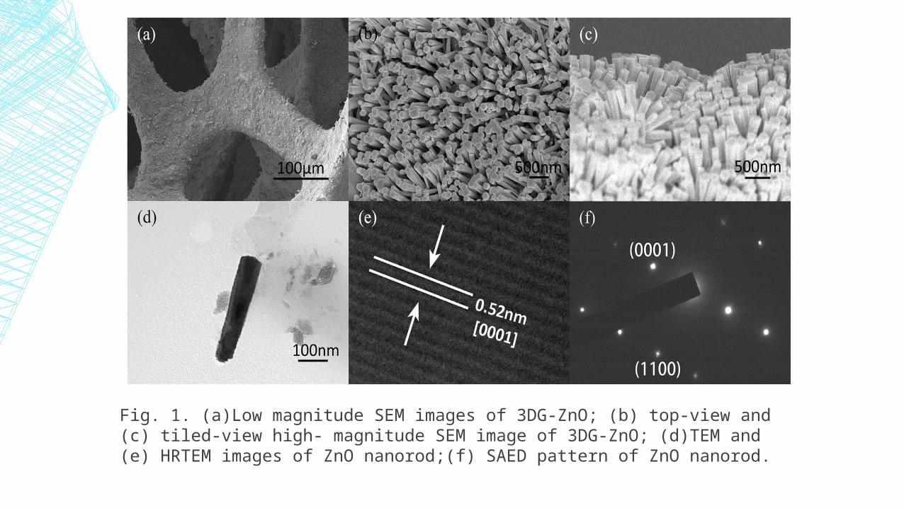
Fig. 1. (a)Low magnitude SEM images of 3DG-ZnO; (b) top-view and (c) tiled-view high- magnitude SEM image of 3DG-ZnO; (d)TEM and (e) HRTEM images of ZnO nanorod;(f) SAED pattern of ZnO nanorod.
▪ Shown in low magnitude SEM images (Fig. 1(a)),the surface of three-dimensional graphene framework is fully covered by ZnO with thick density of coverage.
▪ In the top-view high-magnitude image (Fig. 1(b)), ZnO nanorods are in ordered alignment on the surface as arrays with space between the nanorods. Each nanorod shows a uniform monocrystal morphol-ogy with wurtzite structure, which is confirmed by the hexagonal shape of the top surface.
▪ The tiled-view image (Fig. 1(c)) illustrates that vertically aligned ZnO nanorod arrays are formed, and nanorods separate well from each other.
▪ In TEM images in Fig. 1(d), the length of ZnO nanorods is con-firmed to be 600 nm .∼
▪ The electron diffraction pattern in Fig. 1(e) also proves the existence of the wurtzite structure of ZnO crystal.
▪ The corresponding SAED pattern (Fig. 1(f)) reveals that the synthesized products are single-crystalline and grown along c-axis .
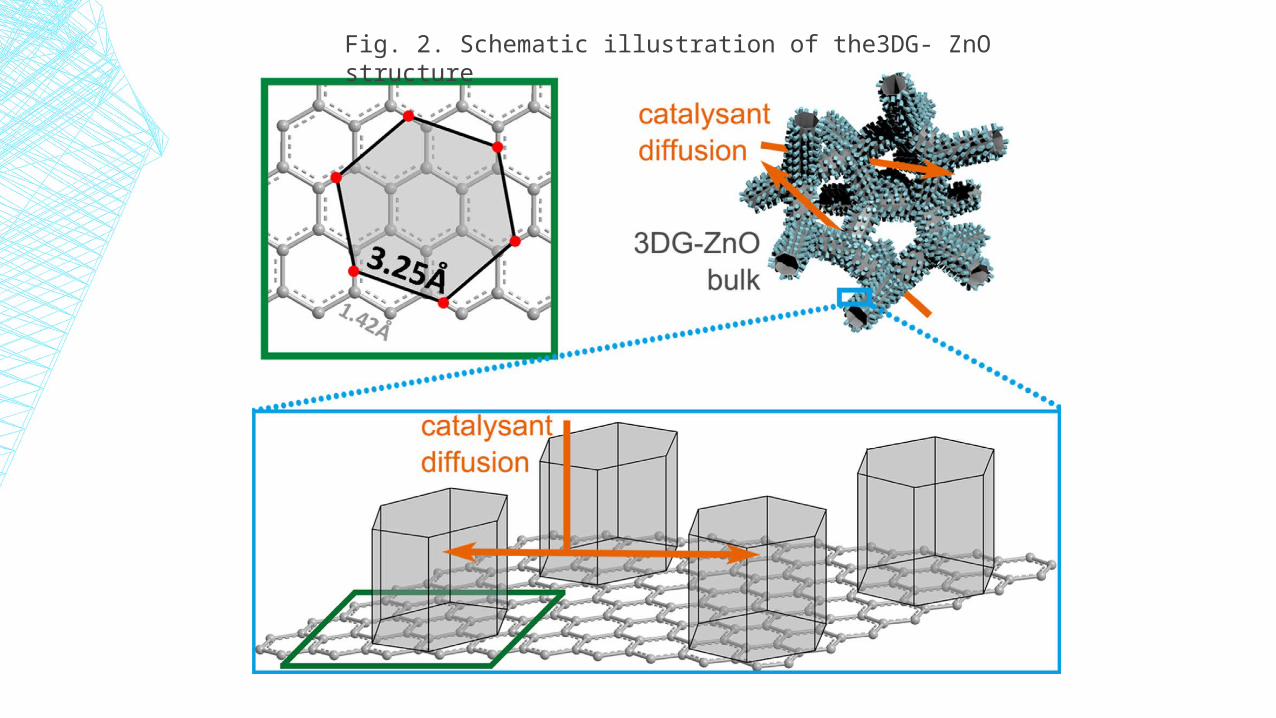
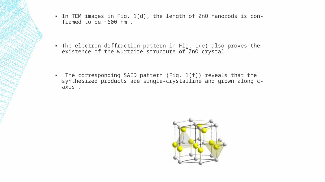
Fig. 2. Schematic illustration of the3DG- ZnO structure
▪ The formation of the regularly aligned ZnO nanorods is due to the epitaxial growth of wurtzite ZnO monocrystal grain on the surface of graphene
▪ As shown in Fig. 2, the length of C-C bond in graphene is 1.42 Å, and the lattice constant ∼c of wurtzite ZnO structure is 3.25 Å, which is in accordance with the distance between ∼two specific bond center illustrated in Fig. 2.
▪ the formation of well- ordered ZnO monocrystal grain on the surface of graphene could occur because of the epitaxial relationship between ZnO and graphene.
▪ The photo catalytic efficiency test was performed with Xenon lamp as the irradiation source.
▪ 3DG-ZnO framework bulk with 5.03 × 10⁻³g ZnO nanorods attached was immersed in 10 mL MO solution.
▪ Then remained in darkness for 30 min for the adsorption of MO, and then irradiated with Xenon lamp for four hours .
▪ Every hour, a sample of 3 mL test solution was placed in quartz colorimetric utensil and analyzed spectrometer .
PHOTOCATALYTIC PERFORMANCE TEST
▪ In the photostability tests, in order to evaluate the endurance of ZnO-3DG structure, a six-hour test was designed that the mass of loaded ZnO was halved.
▪ All other conditions are in consistent with the photocatalytic efficiency test.
▪ After the first test, the ZnO-3DG structure was washed by deionized water and alcohol and then dried before the second test.
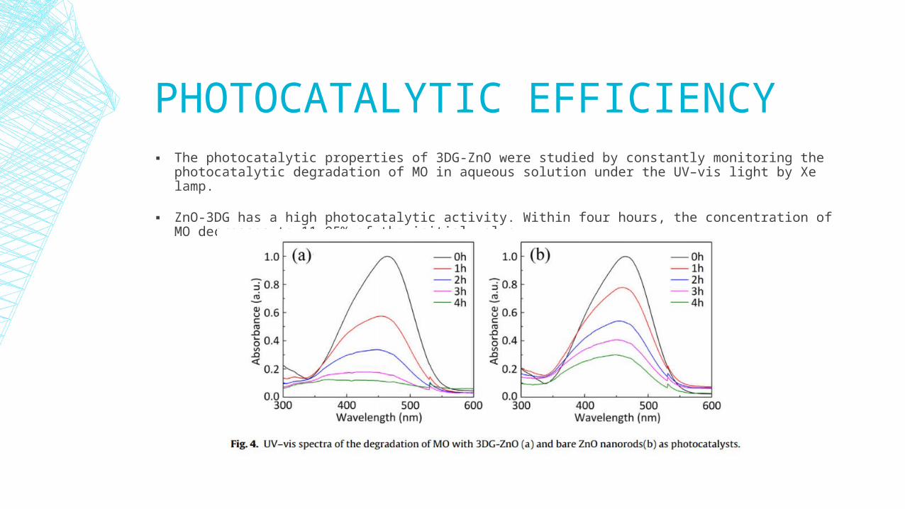
PHOTOCATALYTIC EFFICIENCY▪ The photocatalytic properties of 3DG-ZnO were studied by constantly monitoring the photocatalytic degradation of MO in
aqueous solution under the UV–vis light by Xe lamp.
▪ ZnO-3DG has a high photocatalytic activity. Within four hours, the concentration of MO decreases to 11.95% of the initial value.
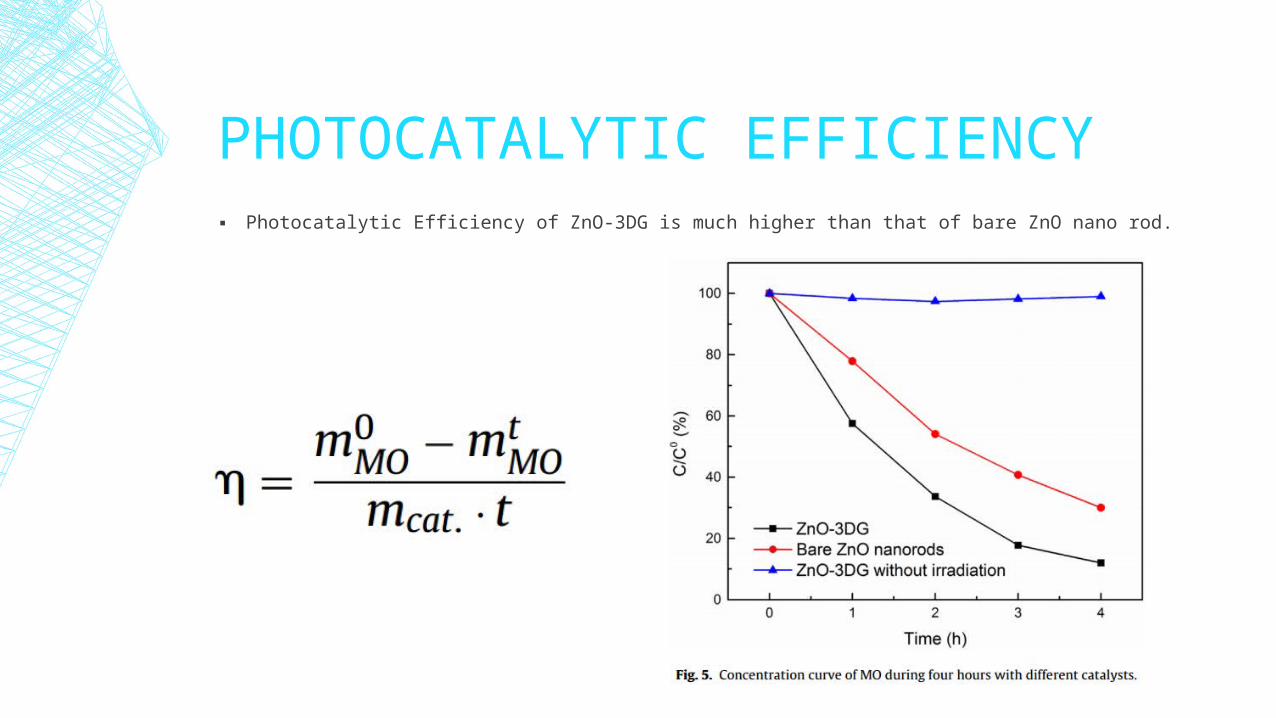
PHOTOCATALYTIC EFFICIENCY▪ Photocatalytic Efficiency of ZnO-3DG is much higher than that of bare ZnO nano rod.
PHOTOCATALYTIC EFFICIENCYHigh efficiency of 3DG-ZnO is attributed to the following reasons :▪ The nano rod arrays morphology of ZnO appearantly increases its specific area. It can make sure that the most active
surfaces are exposed, and increase the surface area for the oxidation of MO on the interface.
▪ Graphene framework processes very high electronic mobility, and plays a role of electron reservoir. The high electronic mobility of graphene may enhance the transfer of photo generated electrons out of ZnO, leaving separated holes in ZnO for the formation of hydroxyl radicals. Therefore, the recombination of photo excited electron-hole pairs is retarded, and the photo activity is improved .
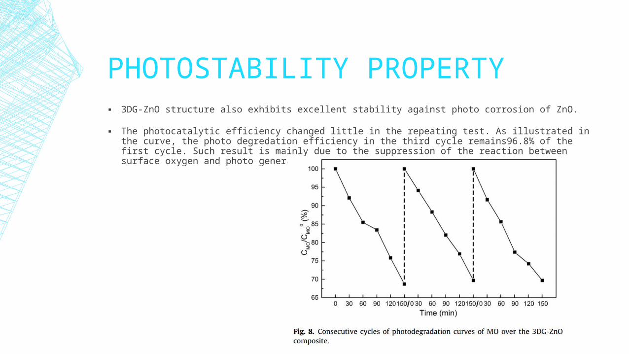
PHOTOSTABILITY PROPERTY ▪ 3DG-ZnO structure also exhibits excellent stability against photo corrosion of ZnO.
▪ The photocatalytic efficiency changed little in the repeating test. As illustrated in the curve, the photo degredation efficiency in the third cycle remains96.8% of the first cycle. Such result is mainly due to the suppression of the reaction between surface oxygen and photo generated holes.
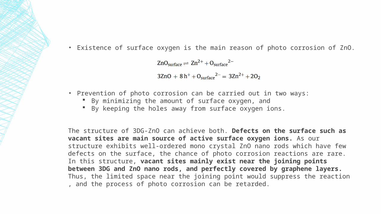
• Existence of surface oxygen is the main reason of photo corrosion of ZnO.
• Prevention of photo corrosion can be carried out in two ways: By minimizing the amount of surface oxygen, and By keeping the holes away from surface oxygen ions.
The structure of 3DG-ZnO can achieve both. Defects on the surface such as vacant sites are main source of active surface oxygen ions. As our structure exhibits well-ordered mono crystal ZnO nano rods which have few defects on the surface, the chance of photo corrosion reactions are rare. In this structure, vacant sites mainly exist near the joining points between 3DG and ZnO nano rods, and perfectly covered by graphene layers. Thus, the limited space near the joining point would suppress the reaction , and the process of photo corrosion can be retarded.
CONCLUSION ▪ In this presentation, we reported ZnO nanorod arrays grown on three-dimensional graphene framework by template-free method.
▪ The rod-array morphology of ZnO crystal increases its surface area and accelerates the mass transfer, allowing more chances for the oxidation of catalysant.
▪ The hybridization of ZnO nanorod arrays and 3DG enhances electron transfer from ZnO to graphene, helping the separation of photo generated holes.
▪ The CO bond existed on the joining points of ZnO and 3DG reduce the activity of surface oxygen ions which may trigger the photo corrosion reaction of ZnO . Therefore, the photo stability of the structure is improved.
▪ Research reveals the mechanism of photocatalytic performance improvement of the structure. It also proves that the hybridization of ZnO to carboneous materials, and similar structures are of great potential in photocatalytic applications.
REFERENCE ▪ Research Paper : Sub-coherent growth of ZnO nanorod arrays on three-
dimensionalgraphene framework as one-bulk high-performance photocatalyst. Written by : Mei Yu, Yuxiao Ma, Jianhua Liu , Xinjie Li, Songmei Li, Shenyao LiuSchool of Materials ∗Science and Engineering, Beihang University, No. 37 Xueyuan Road, Beijing 100191, Chinaa