MEDIDOR DE PASO DE CUERDAS API.pdf
24
LG-5002 Lead Gage OPERATION MANUAL
-
Upload
luisgarcia2608 -
Category
Documents
-
view
222 -
download
0
Transcript of MEDIDOR DE PASO DE CUERDAS API.pdf

7/22/2019 MEDIDOR DE PASO DE CUERDAS API.pdf
http://slidepdf.com/reader/full/medidor-de-paso-de-cuerdas-apipdf 1/24
LG-5002Lead Gage
OPERATION MANUAL

7/22/2019 MEDIDOR DE PASO DE CUERDAS API.pdf
http://slidepdf.com/reader/full/medidor-de-paso-de-cuerdas-apipdf 2/24
L L e e a a d d G G a a g g e e O O p p e e r r a a t t i i o o n n M M a a n n u u a a l l M M o o d d e e l l L L G G - - 5 5 0 0 0 0 2 2
2
©2008 Gagemaker, LP
OMLG50035-01

7/22/2019 MEDIDOR DE PASO DE CUERDAS API.pdf
http://slidepdf.com/reader/full/medidor-de-paso-de-cuerdas-apipdf 3/24
L L e e a a d d G G a a g g e e O O p p e e r r a a t t i i o o n n M M a a n n u u a a l l M M o o d d e e l l L L G G - - 5 5 0 0 0 0 2 2
3
Contents
Introduction
Technical Support 7Product Information and Updates 7
System ComponentsComponent List 9
Setup Procedures
Setting Up the Lead Gage 11Zeroing the Lead Gage 14
Operating Procedures
Inspecting Parts 17
Care and Maintenance
Replacing the Indicator 19Maintenance Tips 21Warranty Information 21

7/22/2019 MEDIDOR DE PASO DE CUERDAS API.pdf
http://slidepdf.com/reader/full/medidor-de-paso-de-cuerdas-apipdf 4/24
L L e e a a d d G G a a g g e e O O p p e e r r a a t t i i o o n n M M a a n n u u a a l l M M o o d d e e l l L L G G - - 5 5 0 0 0 0 2 2
4

7/22/2019 MEDIDOR DE PASO DE CUERDAS API.pdf
http://slidepdf.com/reader/full/medidor-de-paso-de-cuerdas-apipdf 5/24
L L e e a a d d G G a a g g e e O O p p e e r r a a t t i i o o n n M M a a n n u u a a l l M M o o d d e e l l L L G G - - 5 5 0 0 0 0 2 2
5
Congratulations! Your decision to purchase a Gagemaker product above all others on the marketdemonstrates your confidence in our quality and workmanship.
To ensure the high performance and operation of our product, we urge you to use the included referencematerials. They contain important information for proper setup and use of the equipment. Also, werecommend that you follow the care and maintenance tips in this manual to keep the equipment workingin top condition.
If your questions have not been addressed in our reference materials, contact your localrepresentative or a customer service representative at 713-472-7360.

7/22/2019 MEDIDOR DE PASO DE CUERDAS API.pdf
http://slidepdf.com/reader/full/medidor-de-paso-de-cuerdas-apipdf 6/24
L L e e a a d d G G a a g g e e O O p p e e r r a a t t i i o o n n M M a a n n u u a a l l M M o o d d e e l l L L G G - - 5 5 0 0 0 0 2 2
6

7/22/2019 MEDIDOR DE PASO DE CUERDAS API.pdf
http://slidepdf.com/reader/full/medidor-de-paso-de-cuerdas-apipdf 7/24
L L e e a a d d G G a a g g e e O O p p e e r r a a t t i i o o n n M M a a n n u u a a l l M M o o d d e e l l L L G G - - 5 5 0 0 0 0 2 2
7
Introduction
The lead gage inspects both internal and external thread lead using contact points that seat in thethreads of a part. Thread lead is the distance between threads, measured on a plane parallel to thecenterline of the threaded part. The pitch of the thread determines the diameter of the contact pointsrequired for taking measurements (refer to the tables for ACME, Stub ACME, UN and API Threads inthe Setup Procedures section of this manual).
Gagemaker’s lead gage, Model LG-5002, uses two contact points to inspect thread lead. One fixedcontact point at the rear of the gage and one moveable contact point at the front of the gage providecomplete stability when taking thread lead measurements.
Before inspecting parts, the lead gage must be preset to a nominal predetermined dimension, using alead gage setting standard. These setting standards are manufactured according to ANSI and APIspecifications with grooves ground at precise increments. The increments are normally set at ¼”intervals from 1” – 4”. Lead standards are available for ACME, Stub ACME, UN and API threads (referto the table in the procedure for Zeroing the Lead Gage in this manual).
To inspect parts, seat the rear contact point of the gage into the thread of the part. Then, seat the
moveable contact point at the front of the gage in the thread. Apply pressure to the nose of the gagewith an index finger and sweep from side to side to get an indicator reading. It is recommended that thegage be zeroed periodically during use to maintain accurate readings.
Technical Support
Phone: 713-472-7360Hours: Monday – Friday 8AM – 5PM (CST)
Product Information and Updates
Visit our web site at: www.gagemaker.com

7/22/2019 MEDIDOR DE PASO DE CUERDAS API.pdf
http://slidepdf.com/reader/full/medidor-de-paso-de-cuerdas-apipdf 8/24
L L e e a a d d G G a a g g e e O O p p e e r r a a t t i i o o n n M M a a n n u u a a l l M M o o d d e e l l L L G G - - 5 5 0 0 0 0 2 2
8

7/22/2019 MEDIDOR DE PASO DE CUERDAS API.pdf
http://slidepdf.com/reader/full/medidor-de-paso-de-cuerdas-apipdf 9/24
L L e e a a d d G G a a g g e e O O p p e e r r a a t t i i o o n n M M a a n n u u a a l l M M o o d d e e l l L L G G - - 5 5 0 0 0 0 2 2
9
System Components
Take some time to become familiar with all the parts that make up the lead gage by reviewing thelabeled diagram below. The part names are important for understanding the operatinginstructions.
Component List
Item Descrip tion Qty Item Description Qty
1 Main Body 1 9 Moving Contact Point Assembly 1
2 Adjustment Knob 1 10 Fixed Contact Point Bar 1
3 Indicator Assembly 1 11 Bushings 2
4 Clamp Screw 1 12 Indicator Push Rod 1
5 Thru hole Clamp 1 13 Indicator Push Rod Sleeve 1
6 Threaded Clamp 4 14 Indicator Hold Down Screws 4
7 Back Yoke 1 15 Yoke Hold Down Screws 2
8 Front Yoke 1 16 Contact Point Assembly Hold Down Screws 2
1614
9 13 12 11
15
87 6
5 10
42 1
3

7/22/2019 MEDIDOR DE PASO DE CUERDAS API.pdf
http://slidepdf.com/reader/full/medidor-de-paso-de-cuerdas-apipdf 10/24
L L e e a a d d G G a a g g e e O O p p e e r r a a t t i i o o n n M M a a n n u u a a l l M M o o d d e e l l L L G G - - 5 5 0 0 0 0 2 2
10

7/22/2019 MEDIDOR DE PASO DE CUERDAS API.pdf
http://slidepdf.com/reader/full/medidor-de-paso-de-cuerdas-apipdf 11/24
L L e e a a d d G G a a g g e e O O p p e e r r a a t t i i o o n n M M a a n n u u a a l l M M o o d d e e l l L L G G - - 5 5 0 0 0 0 2 2
11
Setup Procedures
Setting Up the Lead Gage
Materials Needed:
• Lead gage • Calipers
• Contact points (2) • Paper clip
Setting up the lead gage, involves installing the proper size contact points for the application (refer to thetable below for selecting the proper model contact point for ACME, Stub ACME, UN threads or APIthreads).
ACME or Stub ACME Threads UN Threads
Thread Pitch Contact Point Model No. Thread Pitch Contact Point Model No.
1 pitch T531T 1 pitch T562
1.5 pitch T344T 2 pitch T288
2 pitch T266T 3 pitch T188
2.5 pitch T219T 3.5 pitch T188
3 pitch T188T 4 pitch T1443.5 pitch T144T 4.5 pitch T128
4 pitch T128T 5 pitch T115
5 pitch T105T 5.5 pitch T105
6, 7 pitch T090T 6 pitch T096
8 pitch T062T 8 pitch T072
10 pitch T050T 10 pitch T057
12 pitch T041T 12 pitch T050
14 pitch T041T 14 pitch T041
16 pitch T032T 16 pitch T041
18 pitch T032
API Threads
Connection Type
PointDiameter
Thread PitchContact PointModel Number
Hughes Slim Line H-90 0.235” 3 T235
All Hughes H-90 0.200” 3 ½ T200
API Rotary Shouldered Connections 0.144” 4 T144
API Rotary Shouldered Connections 0.128” 4 ½ T128
API Rotary Shouldered Connections 0.115” 5 T115
Truncated for Extreme Line 0.105” 5 ½ T105T
API Rotary Shouldered Connections 0.096” 6 T096API Tubing, Casing and Line Pipe 0.072” 8 T072
Buttress Casing - Lead 0.062” 5 T062
API Tubing and Line Pipe 0.057” 10 T057
API Line Pipe 0.050” 11 ½ T050
API Line Pipe 0.041” 14 T041
API Line Pipe 0.032” 18 T032
API Line Pipe 0.021” 27 T021

7/22/2019 MEDIDOR DE PASO DE CUERDAS API.pdf
http://slidepdf.com/reader/full/medidor-de-paso-de-cuerdas-apipdf 12/24
L L e e a a d d G G a a g g e e O O p p e e r r a a t t i i o o n n M M a a n n u u a a l l M M o o d d e e l l L L G G - - 5 5 0 0 0 0 2 2
12
Setting Up the Lead Gage (continued)
1. Determine the size of contact points to be
used, by the pitch of the thread being
inspected.
2. Using calipers, verify the size of the contact
point.
3. Install one contact point into the moveable
point holder at the front of the gage.
4. Determine the location for the other contact
point based on the interval of lead required for
the inspection. The increments in the lead
gage are set at ¼” intervals from 1” – 4”.
5. Install the remaining contact point into theproper hole.

7/22/2019 MEDIDOR DE PASO DE CUERDAS API.pdf
http://slidepdf.com/reader/full/medidor-de-paso-de-cuerdas-apipdf 13/24
L L e e a a d d G G a a g g e e O O p p e e r r a a t t i i o o n n M M a a n n u u a a l l M M o o d d e e l l L L G G - - 5 5 0 0 0 0 2 2
13
Setting Up the Lead Gage (continued)
6. Once installed, insert a paper clip into the hole
in each contact point and tighten.
7/22/2019 MEDIDOR DE PASO DE CUERDAS API.pdf
http://slidepdf.com/reader/full/medidor-de-paso-de-cuerdas-apipdf 14/24
L L e e a a d d G G a a g g e e O O p p e e r r a a t t i i o o n n M M a a n n u u a a l l M M o o d d e e l l L L G G - - 5 5 0 0 0 0 2 2
14
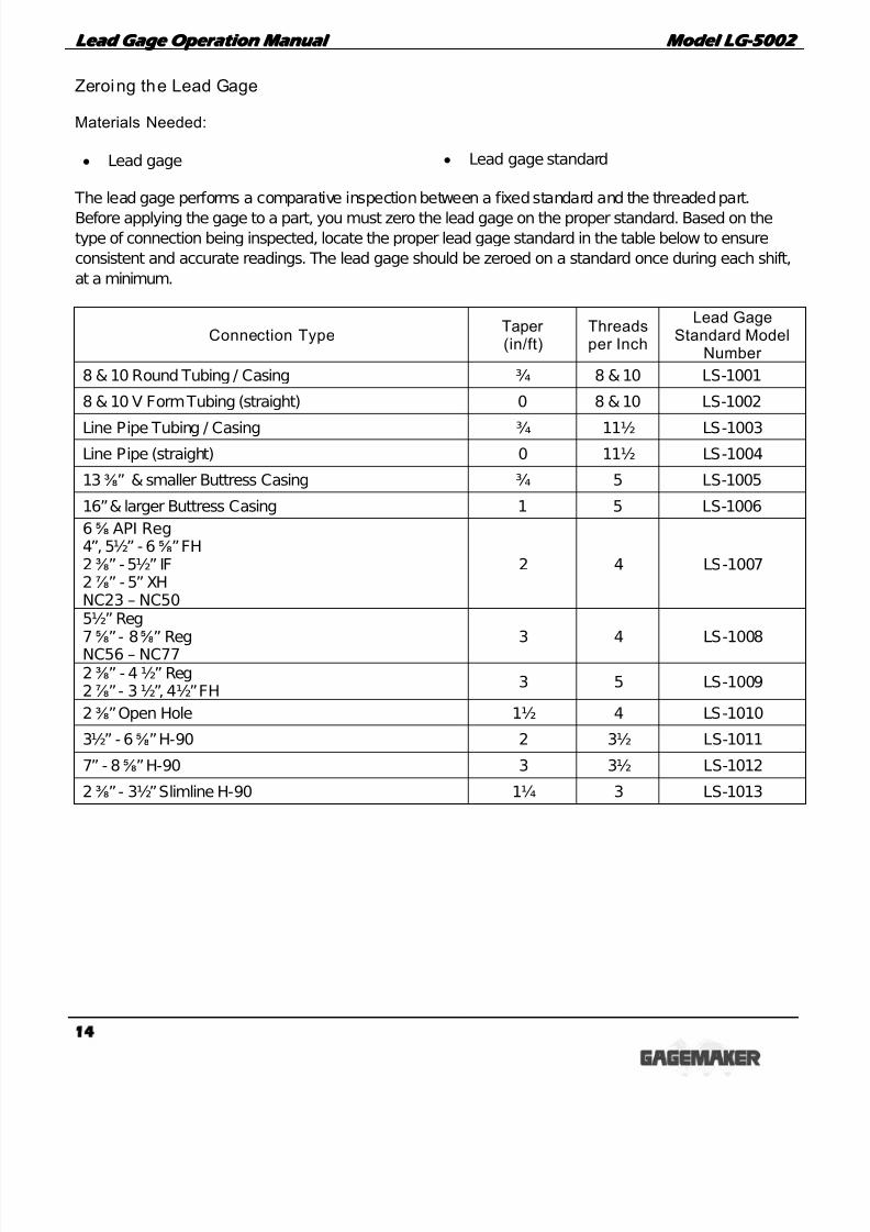
Zeroing the Lead Gage
Materials Needed:
• Lead gage • Lead gage standard
The lead gage performs a comparative inspection between a fixed standard and the threaded part.
Before applying the gage to a part, you must zero the lead gage on the proper standard. Based on thetype of connection being inspected, locate the proper lead gage standard in the table below to ensure
consistent and accurate readings. The lead gage should be zeroed on a standard once during each shift,
at a minimum.
Connection TypeTaper (in/ft)
Threadsper Inch
Lead GageStandard Model
Number
8 & 10 Round Tubing / Casing ¾ 8 & 10 LS-1001
8 & 10 V Form Tubing (straight) 0 8 & 10 LS-1002
Line Pipe Tubing / Casing ¾ 11½ LS-1003Line Pipe (straight) 0 11½ LS-1004
13⅜” & smaller Buttress Casing ¾ 5 LS-1005
16” & larger Buttress Casing 1 5 LS-1006
6⅝ API Reg4”, 5½” - 6⅝” FH2⅜” - 5½” IF2⅞” - 5” XHNC23 – NC50
2 4 LS-1007
5½” Reg7⅝” - 8⅝” RegNC56 – NC77
3 4 LS-1008
2⅜” - 4 ½” Reg2⅞” - 3 ½”, 4½” FH
3 5 LS-1009
2⅜” Open Hole 1½ 4 LS-1010
3½” - 6⅝” H-90 2 3½ LS-1011
7” - 8⅝” H-90 3 3½ LS-1012
2⅜” - 3½” Slimline H-90 1¼ 3 LS-1013

7/22/2019 MEDIDOR DE PASO DE CUERDAS API.pdf
http://slidepdf.com/reader/full/medidor-de-paso-de-cuerdas-apipdf 15/24
L L e e a a d d G G a a g g e e O O p p e e r r a a t t i i o o n n M M a a n n u u a a l l M M o o d d e e l l L L G G - - 5 5 0 0 0 0 2 2
15
Zeroing the Lead Gage (continued)
1. Place the fixed contact point in the first grooveof the standard.
2. Slide the gage over until the fixed contact
point seats against the fence.
3. Place the moveable contact point into the
groove of the setting standard.
Note: For Non-vee threads, pull the lead gage
toward the load flank of the groove in the
standard. For Vee threads, be sure the
contact points touch both flanks of the
groove in the standard.
4. As the moveable contact point touches thestandard, slide the front of the lead gage to
the left until the contact point seats against the
fence.

7/22/2019 MEDIDOR DE PASO DE CUERDAS API.pdf
http://slidepdf.com/reader/full/medidor-de-paso-de-cuerdas-apipdf 16/24
L L e e a a d d G G a a g g e e O O p p e e r r a a t t i i o o n n M M a a n n u u a a l l M M o o d d e e l l L L G G - - 5 5 0 0 0 0 2 2
16
Zeroing the Lead Gage (continued)
5. With the two contact points properly seated in
the grooves and against the fence of the
standard, turn the indicator dial to align the
needle with zero.

7/22/2019 MEDIDOR DE PASO DE CUERDAS API.pdf
http://slidepdf.com/reader/full/medidor-de-paso-de-cuerdas-apipdf 17/24
L L e e a a d d G G a a g g e e O O p p e e r r a a t t i i o o n n M M a a n n u u a a l l M M o o d d e e l l L L G G - - 5 5 0 0 0 0 2 2
17
Operating Procedures
Inspecting Parts
Materials Needed:
• Lead gage • Inspection report
• Part
Inspecting parts using the lead gage involves placing the lead gage’s contact points in the flanks of the
thread to obtain a lead measurement. The two point system on the lead gage provides accurate
readings.
1. After zeroing the lead gage on the standard,
seat the rear contact point into the thread.
2. Tilt the gage forward to seat the moveable
contact point into the thread.
Wear Pad

7/22/2019 MEDIDOR DE PASO DE CUERDAS API.pdf
http://slidepdf.com/reader/full/medidor-de-paso-de-cuerdas-apipdf 18/24
L L e e a a d d G G a a g g e e O O p p e e r r a a t t i i o o n n M M a a n n u u a a l l M M o o d d e e l l L L G G - - 5 5 0 0 0 0 2 2
18
Inspecting Parts (continued)
3. Apply pressure to the nose of the gage with the
index finger. Do not apply excessive force to
the gage, just enough to keep the moveable
point in contact with the thread flanks. Then,
using the rear contact point as the pivot point,
sweep the gage for the measurement.
4. Record any deviations on an inspection or
calibration report.
5. Use the first part you inspected as a control
piece to verify repeatability. Mark the part at the
location where it was inspected and record the
deviation from zero.
6. During the inspection process, periodically
place the lead gage on the control piece toverify the gage’s repeatability.
7/22/2019 MEDIDOR DE PASO DE CUERDAS API.pdf
http://slidepdf.com/reader/full/medidor-de-paso-de-cuerdas-apipdf 19/24
L L e e a a d d G G a a g g e e O O p p e e r r a a t t i i o o n n M M a a n n u u a a l l M M o o d d e e l l L L G G - - 5 5 0 0 0 0 2 2
19
Care and Maintenance
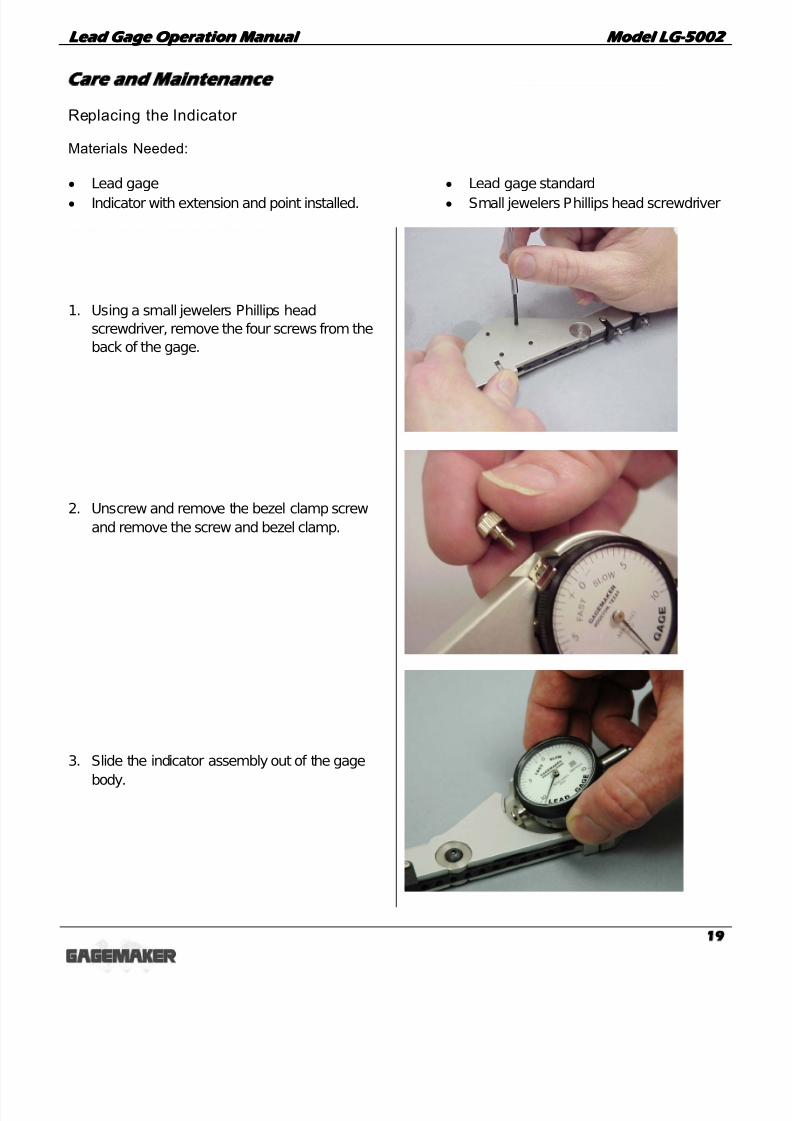
Replacing the Indicator
Materials Needed:
• Lead gage • Lead gage standard
• Indicator with extension and point installed. • Small jewelers Phillips head screwdriver
1. Using a small jewelers Phillips head
screwdriver, remove the four screws from the
back of the gage.
2. Unscrew and remove the bezel clamp screw
and remove the screw and bezel clamp.
3. Slide the indicator assembly out of the gage
body.

7/22/2019 MEDIDOR DE PASO DE CUERDAS API.pdf
http://slidepdf.com/reader/full/medidor-de-paso-de-cuerdas-apipdf 20/24
L L e e a a d d G G a a g g e e O O p p e e r r a a t t i i o o n n M M a a n n u u a a l l M M o o d d e e l l L L G G - - 5 5 0 0 0 0 2 2
20
Replacing the Indicator (continued)
4. Slide the new indicator assembly with pointlever attached back into the body of the lead
gage.
5. Replace the bezel clamp and clamp screw.
6. Replace the four Phillips head screws into the
back of the gage body into the indicator.

7/22/2019 MEDIDOR DE PASO DE CUERDAS API.pdf
http://slidepdf.com/reader/full/medidor-de-paso-de-cuerdas-apipdf 21/24
L L e e a a d d G G a a g g e e O O p p e e r r a a t t i i o o n n M M a a n n u u a a l l M M o o d d e e l l L L G G - - 5 5 0 0 0 0 2 2
21
Maintenance Tips
• Keep all unprotected metal surfaces coated with light oil.
• Avoid dropping the gage or subjecting it to any vibration or impact.
• Keep the gage dry and away from any machine coolant spray.
• Do not force the movement of any of the mechanical parts. The mechanics are designed to movefreely.
• Keep the indicator face clean.
Warranty Information
GAGEMAKER warrants its products to be free from defects in material and workmanship for one yearfrom the date of shipment. At our option, we will repair or replace any defective product upon return,prepaid, properly packed to our factory in Pasadena, Texas. This warranty applies to all products whenused in a normal industrial environment. Any unauthorized tampering, misuse or neglect will make this
warranty null and void. Under no circumstances will GAGEMAKER or any affiliate have any liabilities forloss or for any indirect or consequential damages. The foregoing warranties are in lieu of all otherwarranties expressed or implied, including but not limited to, the implied warranties of merchantabilityand fitness for a particular purpose.

7/22/2019 MEDIDOR DE PASO DE CUERDAS API.pdf
http://slidepdf.com/reader/full/medidor-de-paso-de-cuerdas-apipdf 22/24
L L e e a a d d G G a a g g e e O O p p e e r r a a t t i i o o n n M M a a n n u u a a l l M M o o d d e e l l L L G G - - 5 5 0 0 0 0 2 2
22
NOTES:

7/22/2019 MEDIDOR DE PASO DE CUERDAS API.pdf
http://slidepdf.com/reader/full/medidor-de-paso-de-cuerdas-apipdf 23/24
L L e e a a d d G G a a g g e e O O p p e e r r a a t t i i o o n n M M a a n n u u a a l l M M o o d d e e l l L L G G - - 5 5 0 0 0 0 2 2
23
NOTES:

7/22/2019 MEDIDOR DE PASO DE CUERDAS API.pdf
http://slidepdf.com/reader/full/medidor-de-paso-de-cuerdas-apipdf 24/24
Gagemaker, LP, P.O. Box 87709, Houston, Texas 77287-7709712 East Southmore Ave., Pasadena, Texas 77502
Phone: 713-472-7360Fax: 713-472-7241
Web site: www.gagemaker.com