ISA 5.3-1983.01.01
22
7/26/2019 ISA 5.3-1983.01.01 http://slidepdf.com/reader/full/isa-53-19830101 1/22
Transcript of ISA 5.3-1983.01.01

7/26/2019 ISA 5.3-1983.01.01
http://slidepdf.com/reader/full/isa-53-19830101 1/22
7/26/2019 ISA 5.3-1983.01.01
http://slidepdf.com/reader/full/isa-53-19830101 2/22
ISA-5.3-1983, Graphic Symbols for Distributed ControVShared Display Instrumentation, Logic and
Computer Systems
ISBN 0-87664-707-7
Copy right 198 3 by the Instrumen t Society of Am erica. All rights reserved. Printed in the United
States of America. No part of this publication may be reproduced, stored in a retrieval system, or
transmitted in any form or by any means (electronic, mechanical, photocopying, recording, or
otherwise), without the prior written permission of the publisher.
ISA
67 Alexander D rive
P.O. Box 12277
Research Triangle Park, North Carolina 27709

7/26/2019 ISA 5.3-1983.01.01
http://slidepdf.com/reader/full/isa-53-19830101 3/22

7/26/2019 ISA 5.3-1983.01.01
http://slidepdf.com/reader/full/isa-53-19830101 4/22
NAME
D. E. Rapley, Cha irman
A. Bohnenbe rger, Secretary (deceased )
R. Barber
G.
V.
Barta
G. Bennett
J. Biggs
R. V. Bins
M. A. Blaschke
C. T. Carroll
W. Cohen
W. M . Dillow
R. E. Dragoo
S. E. Gaertner
L. K. Haberman
E. Harrison
T. Herrera
C. Kenyon
S. Keown
T. H. King
P. Kramer
G. K. Kullberg
D. G. L eonard
G. Lind
W. M. Lydecker
R. E. Lynch
J. E. Macko
A. F. Marks
R. G. Martin
T. C. McAvinew
J.
M. McHenry
T. J. M yron, Jr.
J. Nevelus
R. L. Nicholson
H. C. Prendergast
W. A. Rock
F. Sandt
R. Shearer
J. W. Stuckey
w. s u
R. C. von Brecht
S. W h take r
J. H . Young
4
COMPANY
Stearns-Roger Enginee ring Corporation
Johns-Ma nville Sales Corporation
Ralph M. Parsons Company
Dow Corning Corporation
Bechtel Power Corporation
Dow Chemical USA
Toledo E dison Com pany
Weyerhaeuser Company
Foster Wheeler
M. W. Kellogg Co.
Gulf Scien ce Technology
Honeyw ell, Inc.
Bechtel Inc.
Bailey Meter Com pany
Exxon Coal USA
Stone Web ster Engineering Corporation
Amoco Oil
Diamond Shamrock C orp.
Ralph M. Parsons Company
Ralph M. Parsons Company
Dow Corning Corporation
Aramco Services
Sybro n Taylor
Carnation C o
Bec h el Pet ole um
Westinghouse
Bech el Pet ole um
A. E. Staley Manufacturing
International Coal Refining Co.
Brown Root
Foxboro Comp any
Bechtel Power Corporation
Sohio
Coors Container Co.
International E ngineering
Pennsylvania Power Light
Stone &We bste r Engineering Corp
Georgia Pacific Corporation
Stearns-Roger Eng ineering Corporation
M. W. Kellogg Co.
Tex-A-Mation
Bechtel Power Corporation
ISA-S5.3-1983
7/26/2019 ISA 5.3-1983.01.01
http://slidepdf.com/reader/full/isa-53-19830101 5/22
This Standard was approved for publication by the ISA Standards and Practices Board in
June
1982.
NAME
T. J. Harrison, Chairman
P. Bliss
W. Calder
N. Conger
B. Feikle
R. T. Jones
R. Ke ller
O.
P. Love tt, Jr.
E. C. Magison
A. P. McCauley
J. W. Mock
E. M. Nesvig
G. Platt
R. Prescott
W. C. Weidman
K. A. Whitman
J. R. William s
B. A. Christensen*
L. N. Com bs*
R. L. Galley*
R. G. Ma rvin*
W. B. Miller*
R. L. Nickens*
COMPANY
IBM Corporation
Consultant
The Foxboro Company
Continental O il Co.
Bailey Controls Co.
Philadelphia E lectric Co.
Boeing Company
Isis Corp.
Honeywell, Inc.
Diamond Shamrock C orp.
EG&G Idaho, Inc.
ERDCO Engineering Corp.
Bechtel Power Corp.
Moore Products Company
Gilbert Associates
Allied Chemical Corp.
Stearns-Roger, Inc.
Moore Products Company
*Director Emeritus
ISA-S5.3-1983 5

7/26/2019 ISA 5.3-1983.01.01
http://slidepdf.com/reader/full/isa-53-19830101 6/22

7/26/2019 ISA 5.3-1983.01.01
http://slidepdf.com/reader/full/isa-53-19830101 7/22

7/26/2019 ISA 5.3-1983.01.01
http://slidepdf.com/reader/full/isa-53-19830101 8/22

7/26/2019 ISA 5.3-1983.01.01
http://slidepdf.com/reader/full/isa-53-19830101 9/22
1 Purpose
The purpose of this standard is to establish docume ntation for that class of instrumen tation
consisting of computers, programm able controllers, minicomp uters and micro-processor based
system s that have sha red control, shared display or other interface features. Sym bols are
provided for interfacing field instrumentation, control room instrumentation and other hardw are to
the above. Terminology is defined in the broades t generic form to describe the various
categories of these devices.
It is not the intent of this standard to m andate the us e of eac h type symb ol for eac h occu rrence of
a gene ric device within the overall control system. Such usage could result in undue complexity
in the cas e of a Piping and Instrument Drawing (P&ID). If, for example, a com puter compo nent is
an integral part of a d istributed control system, the use of the com puter symb ol would normally
be an undesirable redundancy. If, however, a sepa rate general purpose com puter is interfaced
with the system, the inclusion of the com puter symbo l may provide the degree of clarity ne eded
for control system understand ing.
This standa rd attempts to provide the users with defined symbolism and rules for usage, which
may be app lied as needed to provide sufficient clarity of intent. Th e extent to which these
symb ols are applied to various types of drawings remains with the u sers. The symb ols may be as
simple or complex as need ed to define the process.
2 Scope
This s tandard satisfies the requiremen ts for symb olically representing the func tions of distributed
ControVshared display instrumentation, logic, and com puter systems. Th e instrumentation is
generally co mpo sed of field ha rdware comm unication networks and con trol room operator
devices. This standard is applicable to all industries using p rocess control and instrumentation
systems.
No effort will be made on the flow diagram to explain the internal construction, configuration, or
metho d of operation of this type of instrumentation, logic and com puter systems. Personnel
needing to und erstand flow diagrams must have a basic unde rstanding of the total system in
order to correctly interpret the diagram. The type of compu tation or the use of the p rocess
variable w ithin a program is not indicated except in those case s where the process variable is an
integral part of the co ntrol strategy. In applications where all instrument system data base
information is available to the co mpu ter via the com mun ication link, the depiction of the com puter
interconnections is optional in order to co nserve space on flow diagrams.
2.1
App l ication to w ork act iv i t ies
This standard is intended for use whenever any reference to an instrument is required. Such
references m ay be required for the following use s as well as o thers:
Flow diagram s, process and m echan ical;
Instrumentation system diagrams;
Specifications, purchase orders, m anifests, and other lists;
ISA-S5.3-1983
9

7/26/2019 ISA 5.3-1983.01.01
http://slidepdf.com/reader/full/isa-53-19830101 10/22
Construction drawings;
Technical papers, literature, and discussions;
Tagging of instruments; and
Installation, operation, and maintenance instructions, drawings, and records.
2.2
Relat ionship to other ISA s tandards
This standard complements ISA-S5.1, Instrumentation Symbols and Identification, for symbols
and formats representing functional iden tification codes. For clarification of examp les, a limited
amount of ISA-S5.1 symbology has been included in this d ocument.
2.3 Relat ionship to other s tandards
Where applicable, definitions not included in Section 3 are in accordance with ANSI X3/TR-1-77,
Am erican National Dictionary for Information Processing, and/or ISA-S5.1.
3 Def in i t ions and abb rev ia t ions
Acc essible -A system feature that is viewable by and interactive with the operator, and allows
the ope rator to perform user-permissible co ntrol actions, e.g., set point changes, auto-m anual
transfers, or on-off actions.
Ass ignab le-A system feature that permits an operator to chann el (or direct) a signal from one
device to another, without the ne ed for changes in wiring, either by m eans of switches or via
keyboard comma nds to the system.
Co m m un ica tio n l ink-The physical hardware required to interconnect devices for the purpose
of transmitting and/or receiving data.
Co m pu ter co nt ro l system-A system in which all control action takes place within the control
computer. Single or redundant computers may be used.
Con figurable-A system feature that permits selection through entry of keyboard comm ands of
the basic structure and characteristics of a device or system, such as control algorithms, display
formats, or inpu t/output terminations.
C.R.T.-Cathode Ray Tube
D ist rib ut ed c o n tr o l system-Th at class of instrumentation (input/output devices, control
devices and operator interface devices) which in addition to executing the stated control functions
also permits transmission of control, measurement, and operating information to and from a
single or a plurality of use r-specifiable locations, connec ted by a commu nication link.
1 04n put/Out pu
Sh are d controller-A control device that contains a plurality of pre-programm ed algorithms
which are user retrievable, configurable, and connectable, and allows user defined control
strategies or functions to be imp lemented . Con trol of multiple process variables can be
implem ented by sharing the capabilities of a single dev ice of this kind.
10
ISA-S5.3-1983

7/26/2019 ISA 5.3-1983.01.01
http://slidepdf.com/reader/full/isa-53-19830101 11/22

7/26/2019 ISA 5.3-1983.01.01
http://slidepdf.com/reader/full/isa-53-19830101 12/22
4.2 .3 Not norm al ly access ib le to opera tor
1) Sha red blind controller.
2) Shared display ins talled in field.
3)
Computation, signal conditioning in shared controller
4)
May be on com munication link.
5) Normally blind operation.
6)
May be altered by configuration
4.3 Computer symbols
The following symbols should be used where systems include componen ts identified as
com puters, as distinct from an integral processor, which drive the various func tions of a
distributed control system. The com puter component may be integrated with the system via the
data link, or it may be a stand -alone computer.
4.3 .1 Norm al ly access ib le to op era tor
Indicator/Controller/Recorder or Alarm Point- usua lly used to indicate video display.
4.3 .2 Not norm al ly access ib le to opera tor
1) Input/Output interface.
2) Computation/Signal conditioning within a computer.
3)
May be used as a blind controller or a software calculation
module.
4.4 Logic and sequent ial cont ro l sym bols
4.4.1 Gen eral sym bol-For undefined complex interconnecting logic or sequence control. (Also
see ISA-S5.1).
4.4.2 Distributed control interconnecting log ic controller with binary or sequential logic functions.
1) Packaged programm able logic controller, or digital logic
controls integral to the distributed control equipment.
2) Not normally accessible b y the operator.
12
ISA-S5.3-1983

7/26/2019 ISA 5.3-1983.01.01
http://slidepdf.com/reader/full/isa-53-19830101 13/22
4 4 3
Distributed control interconnecting log ic controller with binary or sequential logic functions.
1) Packaged programm able logic controller, or digital logic
controls integral to the distributed control equ ipmen t.
2) Norm ally accessible to the operator.
4.5 Internal system funct ion symbo ls
4 5 1
Compu ta t ion /S igna l cond i t i on ing
n
U
4 6
Commo n symbols
4 6 1
System l ink
-0-o-
1) For block identification refer to ISA -33 .1, Table 2 Func tion
Des g nat¡
o
ns for Re ays II
2) For extensive com putational requirements, use designa tion
C. I Exp a n on su p p e mentar y docu men at on
.
3) Used in conjunc tion with function relay bubb les per ISA-S5.1.
1) Used to indicate either a software link or manufacturer's
system su pplied connections between functions.
2) Alternatively, link can be implicitly shown by contiguous
symbols.
3) May be used to indicate a comm unication link at the u ser's
option.
4.7
Recorders and other his tor ical data retent ion
4 7 1
Conventional hard-wired recording devices such as strip chart recorders shall be shown in
accordance with ISA-33.1. (Refer to Appendix A.2.2. of this standard.)
4 7 2 For assignable recording de vices use S ymb ol 4.2.1.
4 7 3 Long term/mass storage of a process variable by digital mem ory mea ns such as tape, disc,
etc., sha ll be depicted in accordance with 4.2 or 4.3 of this standard, depending on the location of
the device.
5 Ident i f icat ion
For purposes of this standard, identification codes shall be consistent with ISA-33.1, with the
following additions.
5.1
Software alarms
Software alarm s may be identified by placing ISA -S5.1, Table 1, letter designators on the input or
output signal lines of the controls, or other specific integral sys tem componen t. See Section 6
Alarms of this stand ard.
ISA-S5.3-1983
13
7/26/2019 ISA 5.3-1983.01.01
http://slidepdf.com/reader/full/isa-53-19830101 14/22
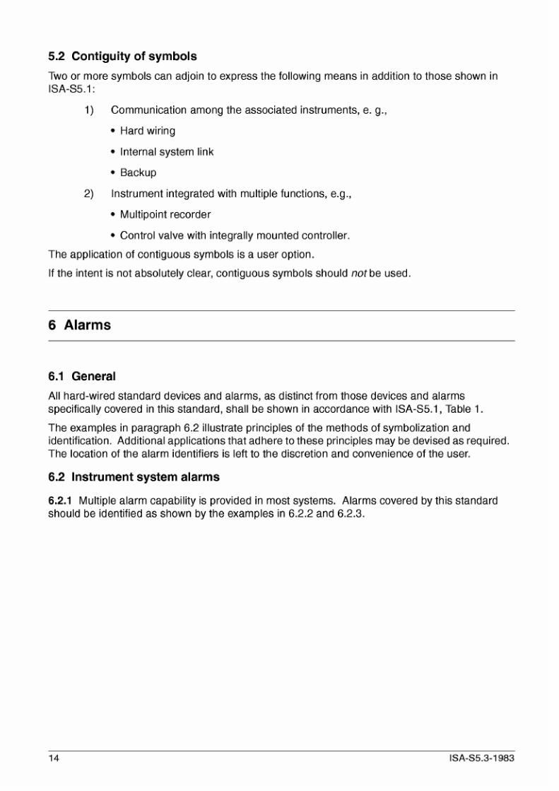
5.2 Cont igui ty of sym bols
Two or more symbols c an ad join to express the following m eans in addition to those show n in
ISA-S5.1:
1)
Comm unication among the associated instruments, e. g.,
Hard wiring
Internal system link
Backup
Instrum ent integrated with multiple functions, e.g.,
Multipoint recorder
Control valve with integrally mounted controller.
2)
The application of contiguous symbols is a user option.
If the intent is not absolutely clear, contiguous symbols should
not
be used.
6
Alarms
6.1 General
All hard-wired standard devices and alarms, as distinct from those devices and a larms
specifically covered in this standard, sh all be shown in accordance w ith ISA-3 3.1, Table 1.
The examples in paragraph 6.2 illustrate principles of the methods of symbolization and
identification. Add itional applications that adhere to these principles may be devised as required.
The location of the alarm identifiers is left to the discretion and convenience of the user.
6.2 Instrument system alarms
6 2 1 Multiple alarm capability is provided in most systems. Alarms co vered by this standard
should b e identified as shown by the examples in 6.2.2 and 6.2.3.
14 ISA-S5.3-1983

7/26/2019 ISA 5.3-1983.01.01
http://slidepdf.com/reader/full/isa-53-19830101 15/22

7/26/2019 ISA 5.3-1983.01.01
http://slidepdf.com/reader/full/isa-53-19830101 16/22

7/26/2019 ISA 5.3-1983.01.01
http://slidepdf.com/reader/full/isa-53-19830101 17/22
r
I
1
r
-
Ei
1
I
I
I
a
i
w
d
Y
4
Figure A5. Shared Display/Shared Control-No Backup
Figure A6. Sh ared Display/Shared Control-With Auxilia
Operator’s Interface Device
04
-1
I
I
r---
-1
I
c
Figure A7. Analog Control-Interfaced with Shared Display.
Figure A8. Shared Display/Shared Control-With Analo
Shared Control Backup Controller Backup
n
‘ Fi
08
r-
I
l i07
_-
1
r-
I
-1
?
I
@
d 5
igure AQ. A nalog ControC-Blind Co ntroller. Shared Display
Figure A lo . Blind Shared Control-With Auxiliary Operator
Interface Backup
ISA-S5.3-1983
17

7/26/2019 ISA 5.3-1983.01.01
http://slidepdf.com/reader/full/isa-53-19830101 18/22
m
r-----
8P
o
I
- 1
Figure Al 1. Supervisory Set Point Control-Analog Con-
troller with Conventional Faceplate. Computer
Supervisory Set Point via Communication Link
*User
identific tion
is
option l
-F:---
-----
I h
I
5p
o
Figure A 1 2 Supervisory Set Point Control-Analog Con-
troller Complete with Conventional Faceplate.
Computer Supervisory Set Point Hardwired.
r
I
@--.P.
8
I
---
I
Q
Figure
A l
3. Supervisory Set Point Control-Shared Dis-
play Shared Control with Full Computer Access
via the Communication Link
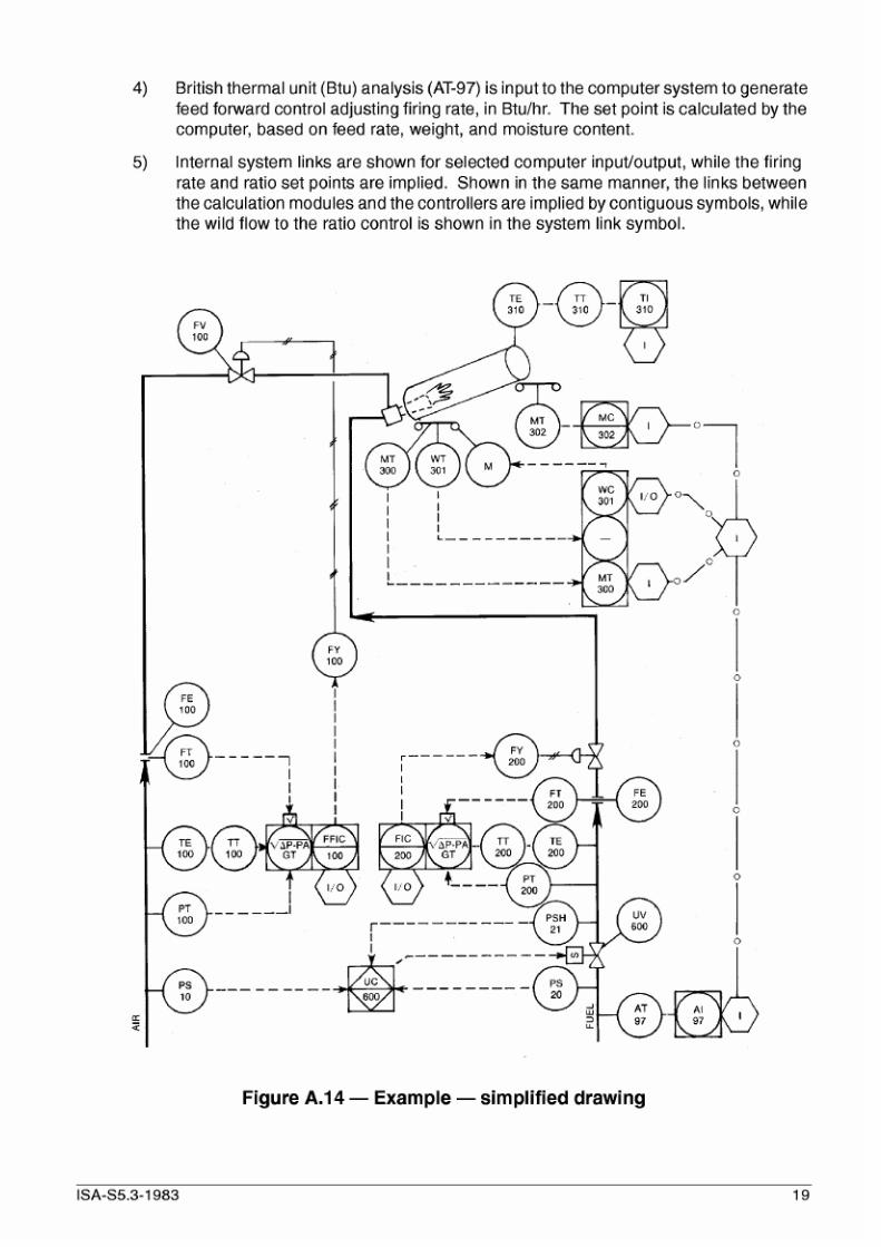
A.2 Typical Flow Diagrams
A.2.1 Figure A. I4 com bines the basic symbols of this standard in a simplified drawing. It is intended
to p rovide a hypothetical examp le and to stimulate the user's imagination in the application of
symbolism to this equipment. Figure
A.14
is arranged in the following m anner:
Volume tric fuel and air flows provide inputs for combustion system firing rate and fuel
air ratio via distributed control instrumen tation. Set po ints for both rate and ratio can
be computer generated.
Combustion air and gas pressu res are monitored by pressure switches which control
the gas safety shuto ff valve via U C-600 distributed control interconnecting logic.
Ma terial moisture content is measu red, dry weight of the input m aterial is calculated,
and feed rate is controlled by MT-300 and WC -301. Discharged m aterial moisture
content is read by MT-302. At this point, firing rate and /orfee d rate could be controlled
by the Distributed Control System (DC S) instrumentation or by the computer taking
other process variables into consideration.
18 ISA-S5.3-1983
7/26/2019 ISA 5.3-1983.01.01
http://slidepdf.com/reader/full/isa-53-19830101 19/22
4)
British therm al unit (Btu) analysis (AT-97) is input to the com puter sys tem to generate
feed forward control adjusting firing rate, in Btu/hr. The set point is calculated by the
computer, based on feed rate, weight, and moisture content.
Internal system links are shown for selected computer input/output, while the firing
rate and ratio set points are implied. Shown in the same manner, the links between
the calculation modules an d the controllers are implied by con tiguous symbols, while
the wild flow to the ratio control is shown in the s ystem link symbol.
5
I
I
I
I
I
I
I I
X I
W
(-J
n
-- -
-
-- -
@ - - _ - _ _ _ -
@*
- - -
97 97
U
Figure A.14 - xample- imp l i f ied drawing
ISA-S5.3-1983 19

7/26/2019 ISA 5.3-1983.01.01
http://slidepdf.com/reader/full/isa-53-19830101 20/22

7/26/2019 ISA 5.3-1983.01.01
http://slidepdf.com/reader/full/isa-53-19830101 21/22

7/26/2019 ISA 5.3-1983.01.01
http://slidepdf.com/reader/full/isa-53-19830101 22/22