Intrfaz d CAN Pr El Sist FMS. Edc 3es
81
11:90-02 Edición 3 es-ES 1 (81) © Scania CV AB 2011, Sweden Introducción Interfaz de CAN para el sistema FMS Introducción Este documento contiene información sobre el sistema FMS estándar, que es una in- terfaz común abierta producida por numerosos fabricantes de camiones rígidos. A partir de mayo de 2011 se introduce en producción también el sistema FMS 2.0. En este documento, se hace referencia a la interfaz FMS de Scania como RTG y el carrocero conecta su propia red FMS a la unidad de mando a través de un conector. • Hasta enero de 2009 incluido, la conexión se realizaba a través del C471 • A partir de febrero de 2009 incluido, la conexión se realiza a través del C137 Los números de serie de chasis de los vehículos correspondientes a cada tipo de co- nexión se indican más adelante en este documento. Importante No se debe conectar ningún otro conector o bus CAN. Una conexión incorrecta po- dría causar un funcionamiento anómalo en los camiones rígidos. En algunos casos, el camión rígido podría incluso detenerse y habría que remolcarlo. En la página web www.fms-standard.com podrá encontrar más información sobre el estándar FMS.
description
interfas scania edc
Transcript of Intrfaz d CAN Pr El Sist FMS. Edc 3es
11:90-02 Edición 3 es
Interfaz de CAN para el sistema FMS
IntroducciónEn la página web www.fms-standard.com podrá encontrar más información sobre el estándar FMS.
IntroducciónEste documento contiene información sobre el sistema FMS estándar, que es una in-terfaz común abierta producida por numerosos fabricantes de camiones rígidos. A partir de mayo de 2011 se introduce en producción también el sistema FMS 2.0.
En este documento, se hace referencia a la interfaz FMS de Scania como RTG y el carrocero conecta su propia red FMS a la unidad de mando a través de un conector.
• Hasta enero de 2009 incluido, la conexión se realizaba a través del C471
• A partir de febrero de 2009 incluido, la conexión se realiza a través del C137
Los números de serie de chasis de los vehículos correspondientes a cada tipo de co-nexión se indican más adelante en este documento.
ImportanteNo se debe conectar ningún otro conector o bus CAN. Una conexión incorrecta po-dría causar un funcionamiento anómalo en los camiones rígidos. En algunos casos, el camión rígido podría incluso detenerse y habría que remolcarlo.
-ES 1 (81)© Scania CV AB 2011, Sweden
Interfaz de CAN para el sistema FMSIntroducción
e forma remota
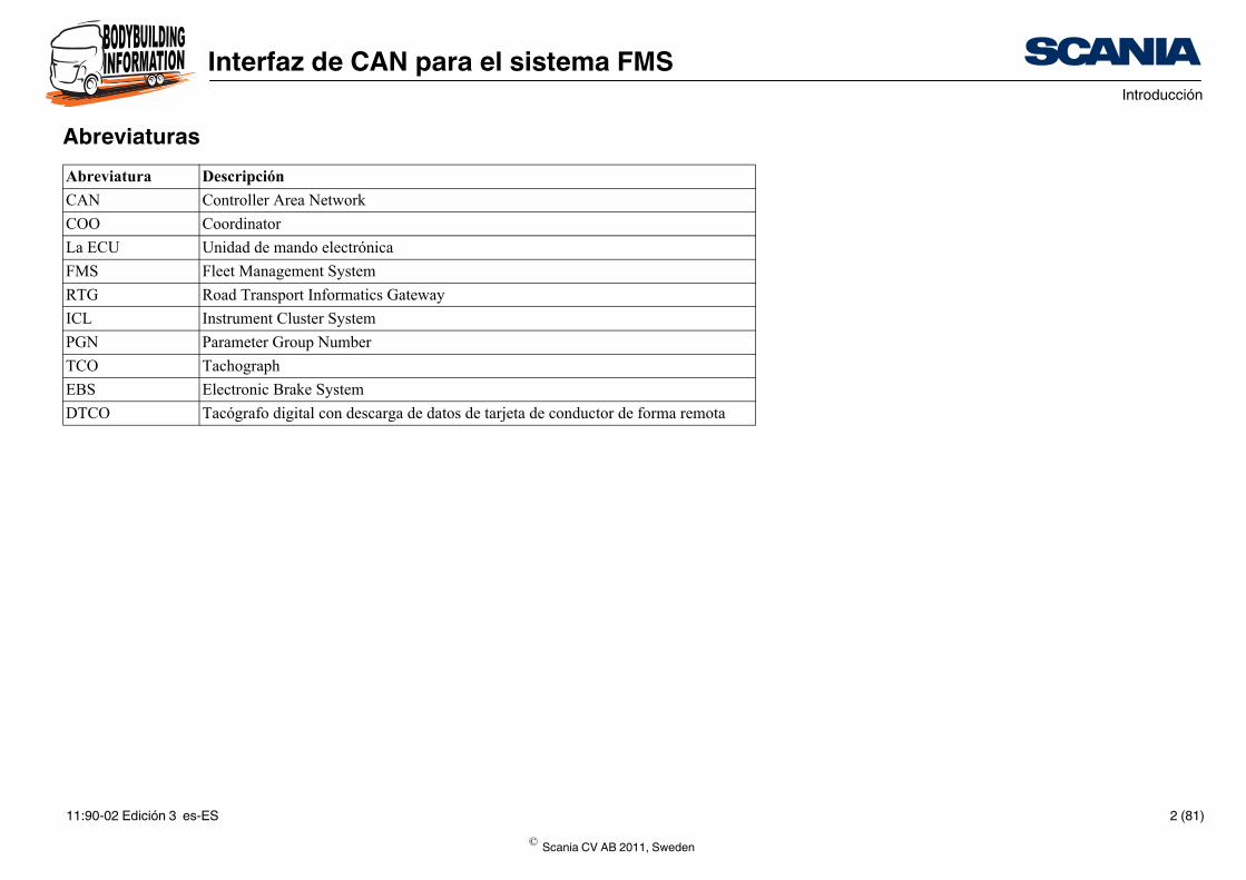
AbreviaturasAbreviatura Descripción
CAN Controller Area Network
COO Coordinator
La ECU Unidad de mando electrónica
FMS Fleet Management System
RTG Road Transport Informatics Gateway
ICL Instrument Cluster System
PGN Parameter Group Number
TCO Tachograph
EBS Electronic Brake System
DTCO Tacógrafo digital con descarga de datos de tarjeta de conductor d
© Scania CV AB 2011, Sweden
11:90-02 Edición 3 es-ES 2 (81)
Interfaz de CAN para el sistema FMSRequisitos para la comunicación con el vehículo a través de la red CAN
Requisitos para la comunicación con el ve-hículo a través de la red CANEn esta sección se indican los requisitos para la comunicación a través de la red CAN con la unidad de mando del sistema RTG en el bus CAN externo. El protocolo de comunicación se basa en la norma SAE J1939, hay partes amplias en la que no se ha implantado. Estas partes cumplen la norma SAE J1939-81 (Network Management), en gran medida la norma SAE J1939-73 (Diagnostics) y partes de SAE J1939-21 (Data Link Layer).
SAE J1939-81 Network ManagementEl espacio para direcciones en un vehículo Scania es estático. Por ello no se necesita la sección Network Management contemplada en la norma SAE J1939-81.
• Las direcciones fijas se emplean en conformidad con Preferred addresses for In-dustry group 0, Global and Industry group 1, On-highway Equipment.
• Las direcciones de origen para equipamiento que normalmente no pertenece al vehículo siguen los requisitos estipulados en las normas J1939, ISO 11992 u OBD/EOBD.
© Scania CV AB 2011, Sweden
11:90-02 Edición 3 es-ES 3 (81)
Interfaz de CAN para el sistema FMSRequisitos para la comunicación con el vehículo a través de la red CAN
SAE J1939-21 Data Link LayerSAE J1939-21 define cinco tipos de mensajes:
• Commands: incompatibles.
• Requests: incompatibles.
• Broadcast/Response: se envía periódicamente toda la información.
• Acknowledgement: incompatibles.
• Group Functions - Proprietary messages och Multipacket messages, TP.CM, TP.DT, compatibles.
Nota:De acuerdo con la sección 5.2.1 de la norma SAE J1939-21, revised version July 1998, los bits de prioridad en los identificadores de mensaje deben descartarse y los receptores deben hacerles caso omiso.
Pautas generales• Las unidades de mando conectadas a un bus CAN deben ser capaces de manejar
una carga del bus del 100%, transmitiendo los mensajes correctos sin ninguna re-ducción funcional importante o anomalía en el funcionamiento.
• Como regla general la carga del bus CAN no debe superar el 80%.
• Evite circuitos de control a través de CAN, porque el tiempo de acceso garantiza-do es relativamente prolongado y los circuitos de control rápidos requieren mucha banda ancha. Si sigue siendo necesario contar con circuitos de control cerrado a través de CAN, estos deben ser perfectamente capaces de enviar los mensajes CAN necesarios a solo la mitad de la frecuencia de transmisión.
ImportanteEs responsabilidad del carrocero asegurarse de que el bus CAN externo se utiliza co-rrectamente.
© Scania CV AB 2011, Sweden
11:90-02 Edición 3 es-ES 4 (81)
Interfaz de CAN para el sistema FMSConectores y cables
Conectores y cablesScania no utiliza conectores SAE J1939.
Scania utiliza cables de par trenzado (retorcido 40 veces por metro) sin blindaje ni cubierta. Las propiedades eléctricas (resistencia, impedancia, capacidad, etc.) se de-finen en la norma SAE J1939-15 Physical Layer Light.
Scania utiliza cables de sección de 0,75 mm2 dentro de la cabina y de 1,5 mm2 en el bastidor. Los conectores CAN (y las terminales de ECU) fuera de la cabina deben es-tar preferentemente chapados en oro.
Los siguientes colores y marcas se aplican a los cables del bus CAN externo: CAN_H debe ser azul y CAN_L blanco. Para evitar confusiones es importante que los cables sean de ese color durante toda la vida útil del vehículo. CAN baja debe estar marcada CAN_L y CAN alta CAN_H.
© Scania CV AB 2011, Sweden
11:90-02 Edición 3 es-ES 5 (81)
Interfaz de CAN para el sistema FMSConexión a RTG
1 4 7 10
2 5 8 11
3 6 9 307
952
12
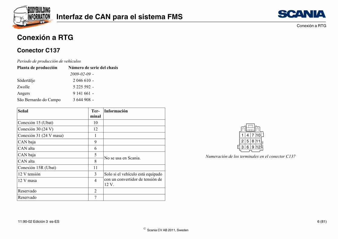
Numeración de los terminales en el conector C137
Conexión a RTGConector C137Periodo de producción de vehículos
Planta de producción Número de serie del chasis
2009-02-09 -
Södertälje 2 046 610 -
Zwolle 5 225 592 -
Angers 9 141 661 -
São Bernardo do Campo 3 644 908 -
Señal Ter-minal
Información
Conexión 15 (Ubat) 10
Conexión 30 (24 V) 12
Conexión 31 (24 V masa) 1
CAN baja 9
CAN alta 6
CAN baja 5No se usa en Scania.
CAN alta 8
Conexión 15R (Ubat) 11
12 V tensión 3 Solo si el vehículo está equipado con un convertidor de tensión de 12 V.
12 V masa 4
Reservado 2
Reservado 7
© Scania CV AB 2011, Sweden
11:90-02 Edición 3 es-ES 6 (81)
Interfaz de CAN para el sistema FMSConexión a RTG
1
C137
307
953
E51RTG
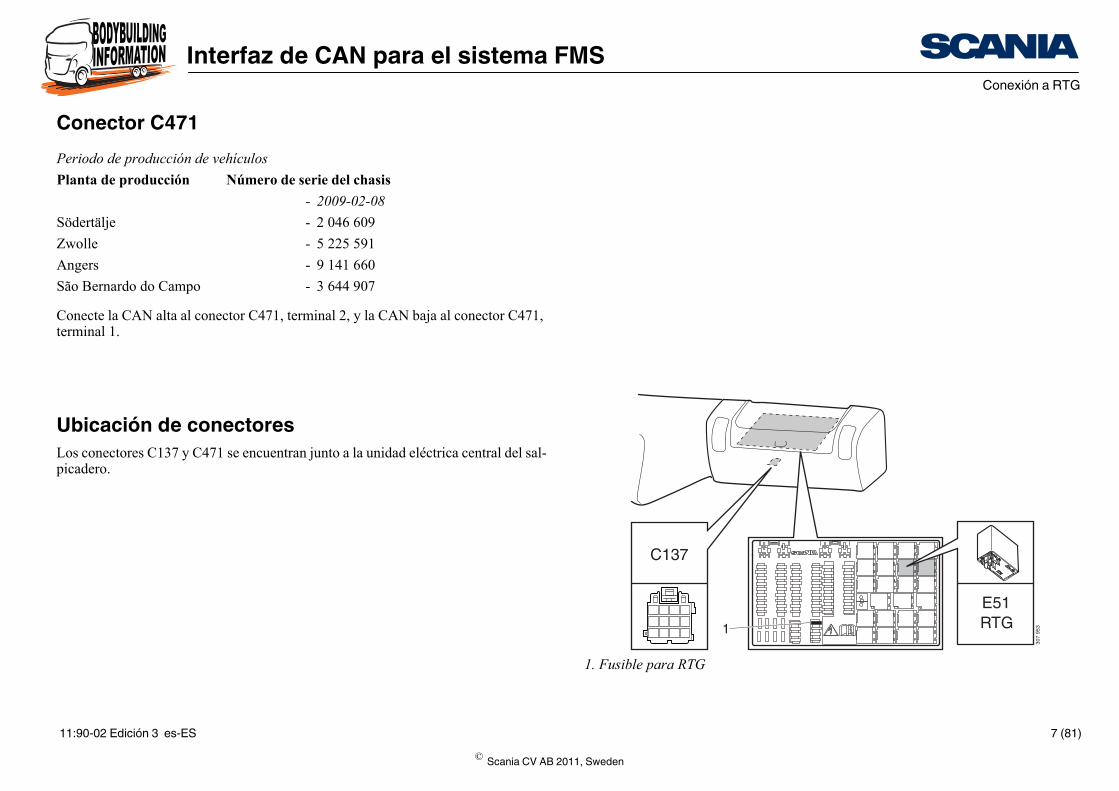
1. Fusible para RTG
Conector C471
Conecte la CAN alta al conector C471, terminal 2, y la CAN baja al conector C471, terminal 1.
Ubicación de conectoresLos conectores C137 y C471 se encuentran junto a la unidad eléctrica central del sal-picadero.
Periodo de producción de vehículos
Planta de producción Número de serie del chasis
- 2009-02-08
Södertälje - 2 046 609
Zwolle - 5 225 591
Angers - 9 141 660
São Bernardo do Campo - 3 644 907
© Scania CV AB 2011, Sweden
11:90-02 Edición 3 es-ES 7 (81)
Interfaz de CAN para el sistema FMSConexión a RTG
< 30 m
> 0.1 m
< 3
m1 2
RTG C137 ECU X
ECU Z ECU Y
307
950
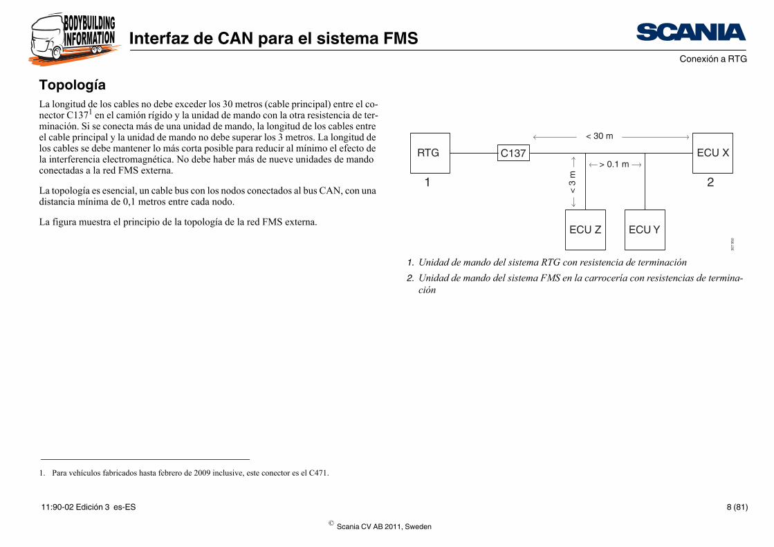
1. Unidad de mando del sistema RTG con resistencia de terminación
2. Unidad de mando del sistema FMS en la carrocería con resistencias de termina-ción
TopologíaLa longitud de los cables no debe exceder los 30 metros (cable principal) entre el co-nector C1371 en el camión rígido y la unidad de mando con la otra resistencia de ter-minación. Si se conecta más de una unidad de mando, la longitud de los cables entre el cable principal y la unidad de mando no debe superar los 3 metros. La longitud de los cables se debe mantener lo más corta posible para reducir al mínimo el efecto de la interferencia electromagnética. No debe haber más de nueve unidades de mando conectadas a la red FMS externa.
La topología es esencial, un cable bus con los nodos conectados al bus CAN, con una distancia mínima de 0,1 metros entre cada nodo.
La figura muestra el principio de la topología de la red FMS externa.
1. Para vehículos fabricados hasta febrero de 2009 inclusive, este conector es el C471.
© Scania CV AB 2011, Sweden
11:90-02 Edición 3 es-ES 8 (81)
Interfaz de CAN para el sistema FMSResistencias de terminación
CAN High
ECU X RTG
CAN Low
CAN High
CAN Low
RR
310
812
2 1 3
C137
6
9
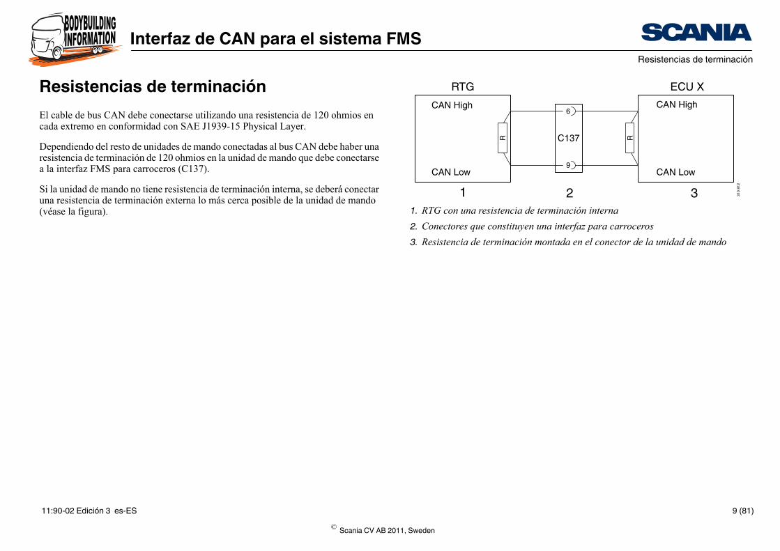
1. RTG con una resistencia de terminación interna
2. Conectores que constituyen una interfaz para carroceros
3. Resistencia de terminación montada en el conector de la unidad de mando
Resistencias de terminaciónEl cable de bus CAN debe conectarse utilizando una resistencia de 120 ohmios en cada extremo en conformidad con SAE J1939-15 Physical Layer.
Dependiendo del resto de unidades de mando conectadas al bus CAN debe haber una resistencia de terminación de 120 ohmios en la unidad de mando que debe conectarse a la interfaz FMS para carroceros (C137).
Si la unidad de mando no tiene resistencia de terminación interna, se deberá conectar una resistencia de terminación externa lo más cerca posible de la unidad de mando (véase la figura).
© Scania CV AB 2011, Sweden
11:90-02 Edición 3 es-ES 9 (81)
Interfaz de CAN para el sistema FMSResistencias de terminación
esistencia de termina-ción en la unidad de ando conectada a C137
Sí
No
No
Sí
Sí
Sí
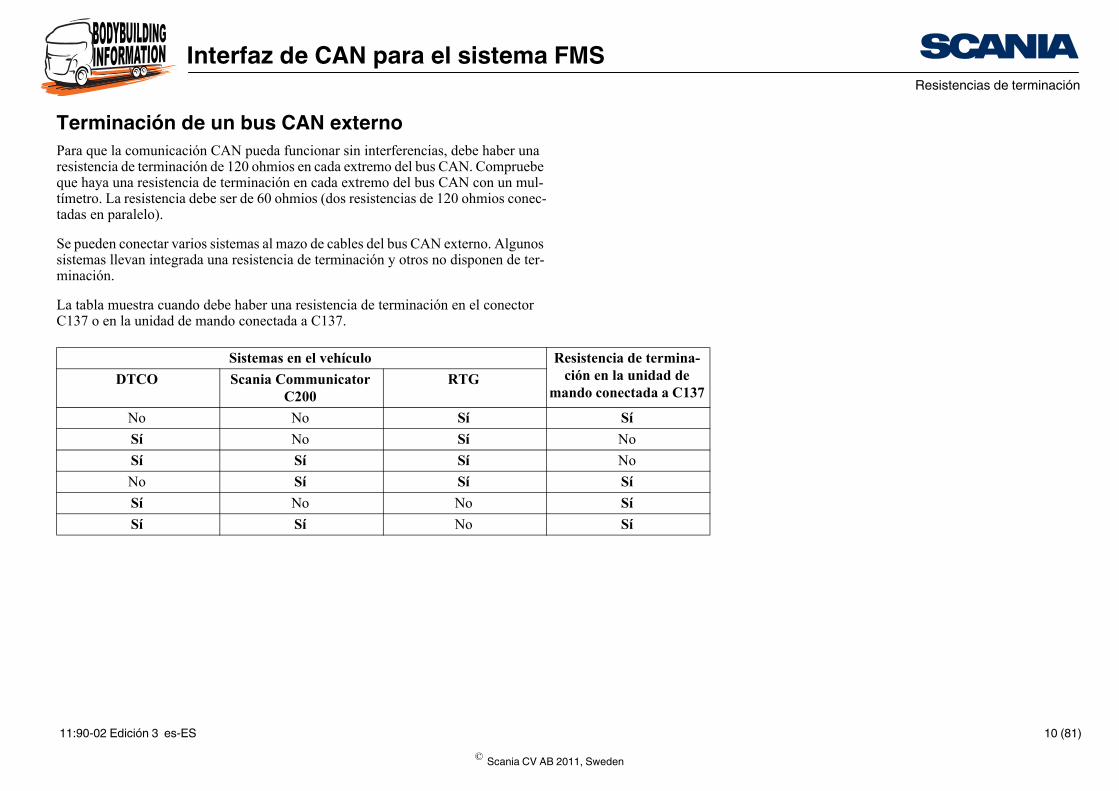
Terminación de un bus CAN externoPara que la comunicación CAN pueda funcionar sin interferencias, debe haber una resistencia de terminación de 120 ohmios en cada extremo del bus CAN. Compruebe que haya una resistencia de terminación en cada extremo del bus CAN con un mul-tímetro. La resistencia debe ser de 60 ohmios (dos resistencias de 120 ohmios conec-tadas en paralelo).
Se pueden conectar varios sistemas al mazo de cables del bus CAN externo. Algunos sistemas llevan integrada una resistencia de terminación y otros no disponen de ter-minación.
La tabla muestra cuando debe haber una resistencia de terminación en el conector C137 o en la unidad de mando conectada a C137.
Sistemas en el vehículo R
mDTCO Scania Communicator
C200RTG
No No Sí
Sí No Sí
Sí Sí Sí
No Sí Sí
Sí No No
Sí Sí No
© Scania CV AB 2011, Sweden
11:90-02 Edición 3 es-ES 10 (81)
Interfaz de CAN para el sistema FMSValidación de errores de comunicación (fin del tiempo de espera programado)
Validación de errores de comunicación (fin del tiempo de espera programado)Evite la comunicación de la CAN cuando la llave de encendido esté en las posiciones de bloqueo o radio. Evítelo tambin durante la secuencia de inicialización de las uni-dades de mando que estén conectadas al bus CAN externo.
Durante el funcionamiento normal, cuando la llave de encendido está en la posición de conducción, no se debe validar un mensaje como ausente (time-out) sino hasta transcurrido un tiempo cinco veces superior al período del mensaje. Se permite un tiempo de validación de errores más prolongado.
Durante la secuencia de arranque del motor, cuando está girando el motor de arran-que, la tensión de alimentación puede ser muy baja. Por eso no se puede garantizar la comunicación desde la unidad de mando del RTG durante esta secuencia. Por este motivo no se registra ningún código de avería relativo a la comunicación CAN con la unidad de mando del RTG cuando la tensión del sistema está por debajo de los 18 voltios.
Al girarse la cerradura de encendido a la posición de conducción, la unidad de mando del RTG empieza a enviar mensajes antes de que transcurran 10.000 ms. No se debe considerar como ausente un mensaje enviado desde la unidad de mando del FMS hasta transcurridos 10.000 ms + (5 x el periodo propio del mensaje). Por ejemplo, si un mensaje tiene un periodo de tiempo de 100 ms, no se debe considerar como au-sente hasta después de que hayan transcurrido 10.000 + (5 x 100) = 10.500 ms. Se permiten tiempos de validación de error más prolongados.
© Scania CV AB 2011, Sweden
11:90-02 Edición 3 es-ES 11 (81)
Interfaz de CAN para el sistema FMSResumen de los mensajes CAN
ador (hex.) Especificación Estándar FMS Interfaz FMS de Scania
01.00 02.00
1D Scania X
27 SAEJ1939-71 X X
17 SAEJ1939-71 X
27 Scania X
64 X
00 SAEJ1939-71 X X X
1E Scania X
27 SAEJ1939-71 X X X
25/18 EB FF 25 SAEJ1939-71 X X
0B Scania X
0B SAEJ1939-71 X
00 SAEJ1939-71 X X X
00 SAEJ1939-71 X X X
10 SAEJ1939-71 X
29 SAEJ1939-71 X
03 SAEJ1939-71 X
00/18 EB FF 00 SAEJ1939-71 X
27 SAEJ1939-71 X
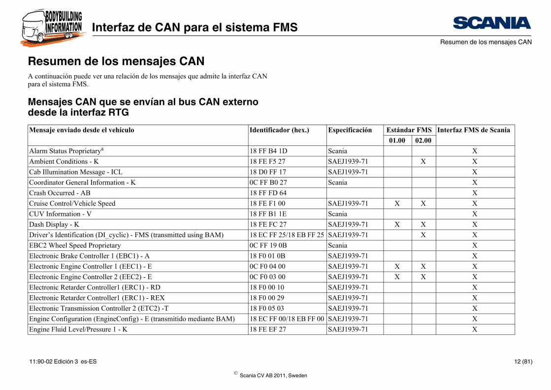
Resumen de los mensajes CANA continuación puede ver una relación de los mensajes que admite la interfaz CAN para el sistema FMS.
Mensajes CAN que se envían al bus CAN externo desde la interfaz RTGMensaje enviado desde el vehículo Identific
Alarm Status Proprietarya 18 FF B4
Ambient Conditions - K 18 FE F5
Cab Illumination Message - ICL 18 D0 FF
Coordinator General Information - K 0C FF B0
Crash Occurred - AB 18 FF FD
Cruise Control/Vehicle Speed 18 FE F1
CUV Information - V 18 FF B1
Dash Display - K 18 FE FC
Driver’s Identification (DI_cyclic) - FMS (transmitted using BAM) 18 EC FF
EBC2 Wheel Speed Proprietary 0C FF 19
Electronic Brake Controller 1 (EBC1) - A 18 F0 01
Electronic Engine Controller 1 (EEC1) - E 0C F0 04
Electronic Engine Controller 2 (EEC2) - E 0C F0 03
Electronic Retarder Controller1 (ERC1) - RD 18 F0 00
Electronic Retarder Controller1 (ERC1) - REX 18 F0 00
Electronic Transmission Controller 2 (ETC2) -T 18 F0 05
Engine Configuration (EngineConfig) - E (transmitido mediante BAM) 18 EC FF
Engine Fluid Level/Pressure 1 - K 18 FE EF
© Scania CV AB 2011, Sweden
11:90-02 Edición 3 es-ES 12 (81)
Interfaz de CAN para el sistema FMSResumen de los mensajes CAN
00 SAEJ1939-71 X X X
00 SAEJ1939-71 X X X
5 Scania X
1 25 SAEJ1939-71 X X X
00 SAEJ1939-71 X X X
00 SAEJ1939-71 X X
00 Scania X
25 SAEJ1939-71 X
EE SAEJ1939-71 X X X
00 SAEJ1939-71 X
minar SAEJ1939-71 X
27 Scania X
5 SAEJ1939-71 X X X
EE SAEJ1939-71 X X X
17 SAEJ1939-71 X
5/18EBFF25 SAEJ1939-71 X X X
25 SAEJ1939-71 X X X
C 0B SAEJ1939-71 X
CVS.
ador (hex.) Especificación Estándar FMS Interfaz FMS de Scania
01.00 02.00
Engine Hours, Revolutions - E 18 FE E5
Engine Temperature 1 - E 18 FE EE
Mensaje de error - FMS 18FFFF2
FMS-standard Interface Identity/Capabilities (FMS Std Interface) - FMS 1C FD D
Fuel Consumption - E 18 FE E9
Fuel Economy - E 18 FE F2
General Purpose Message 1 - E 18 FF 60
High Resolution Fuel Consumption (Liquid) (HRLFC) - FMS 18 FD 09
High Resolution Vehicle Distance - TCO 18 FE C1
Inlet/Exhaust Conditions 1 - E 18 FE F6
Acoplamiento de la PTOb Por deter
PTO Information Proprietary - K 18 FF 90
Service Information (ServiceInformation) - FMS 18FEC02
Tachograph - TCO1 0C FE 6C
Time/Date (TimeDate) - ICL 18 FE E6
Vehicle Identification (VehicleId) - FMS (transmitted using BAM) 18ECFF2
Vehicle Weight (Vehicle Weight) - FMS 18 FE EA
Wheel Brake Lining Remaining Information (EBC4WheelBrakeLiningRemainingInf) - Ac
1C FE A
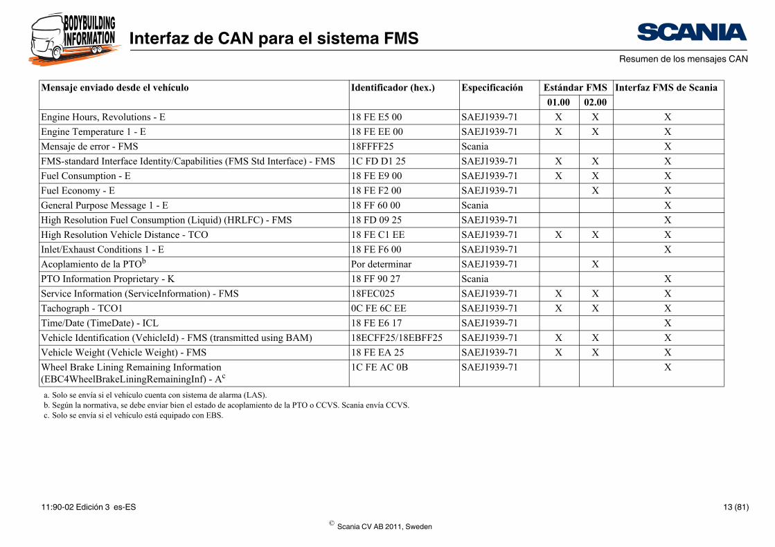
a. Solo se envía si el vehículo cuenta con sistema de alarma (LAS).b. Según la normativa, se debe enviar bien el estado de acoplamiento de la PTO o CCVS. Scania envía Cc. Solo se envía si el vehículo está equipado con EBS.
Mensaje enviado desde el vehículo Identific
© Scania CV AB 2011, Sweden
11:90-02 Edición 3 es-ES 13 (81)
Interfaz de CAN para el sistema FMSDescripción detallada de los mensajes CAN
Descripción detallada de los mensajes CANEn las tablas que aparecen aquí se utilizan los conceptos siguientes:
• Not defined: sin definir en SAE J1939
• Not used: definido en SAE 1939 pero Scania no lo utiliza
Para el contenido de los mensajes con números de grupos de parámetros (PGN) es-pecificados por Scania:
• Not defined: sin definir por Scania
© Scania CV AB 2011, Sweden
11:90-02 Edición 3 es-ES 14 (81)
Interfaz de CAN para el sistema FMSDescripción detallada de los mensajes CAN
State Resolution Limits Note
0000
0001
0010
0011
0100
0101
0110
0111
1000
1001
1010
1100..1101
1110
1111
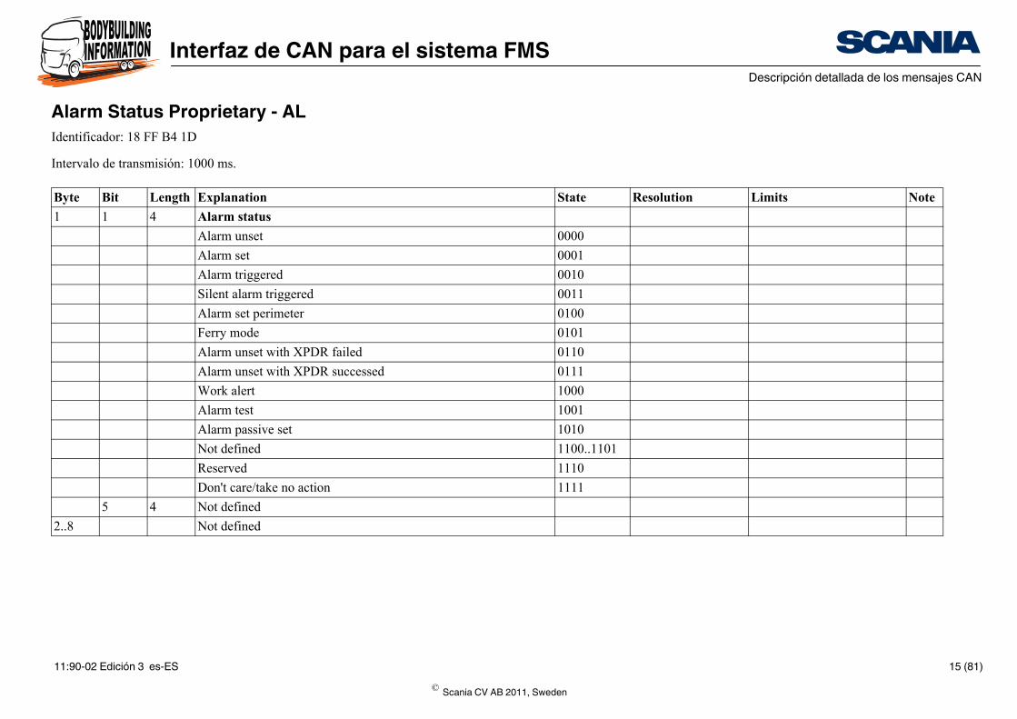
Alarm Status Proprietary - ALIdentificador: 18 FF B4 1D
Intervalo de transmisión: 1000 ms.
Byte Bit Length Explanation
1 1 4 Alarm status
Alarm unset
Alarm set
Alarm triggered
Silent alarm triggered
Alarm set perimeter
Ferry mode
Alarm unset with XPDR failed
Alarm unset with XPDR successed
Work alert
Alarm test
Alarm passive set
Not defined
Reserved
Don't care/take no action
5 4 Not defined
2..8 Not defined
© Scania CV AB 2011, Sweden
11:90-02 Edición 3 es-ES 15 (81)
Interfaz de CAN para el sistema FMSDescripción detallada de los mensajes CAN
State Resolution Limits Note
0,5 kPa/bit 0 a 125 kPa
FE
FF
0.03125°C/bit -273 a +1,735.0 °C
FExx
FFxx
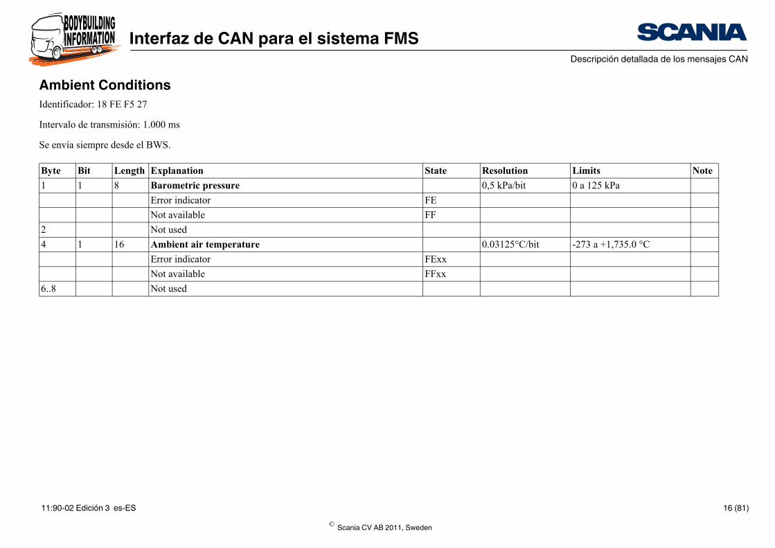
Ambient ConditionsIdentificador: 18 FE F5 27
Intervalo de transmisión: 1.000 ms
Se envía siempre desde el BWS.
Byte Bit Length Explanation
1 1 8 Barometric pressure
Error indicator
Not available
2 Not used
4 1 16 Ambient air temperature
Error indicator
Not available
6..8 Not used
© Scania CV AB 2011, Sweden
11:90-02 Edición 3 es-ES 16 (81)
Interfaz de CAN para el sistema FMSDescripción detallada de los mensajes CAN
State Resolution Limits Note
0.4% 0 a 100%
FEh
FFh
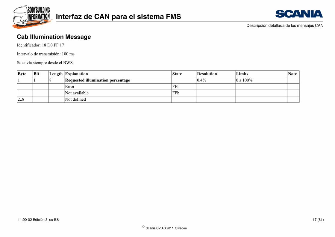
Cab Illumination MessageIdentificador: 18 D0 FF 17
Intervalo de transmisión: 100 ms
Se envía siempre desde el BWS.
Byte Bit Length Explanation
1 1 8 Requested illumination percentage
Error
Not available
2..8 Not defined
© Scania CV AB 2011, Sweden
11:90-02 Edición 3 es-ES 17 (81)
Interfaz de CAN para el sistema FMSDescripción detallada de los mensajes CAN
State Resolution Limits Note
00
01
10
11
00
01
10
11
A
00
01
10
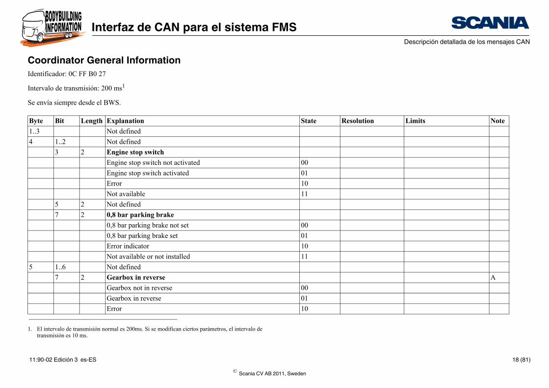
Coordinator General InformationIdentificador: 0C FF B0 27
Intervalo de transmisión: 200 ms1
Se envía siempre desde el BWS.
1. El intervalo de transmisión normal es 200ms. Si se modifican ciertos parámetros, el intervalo de transmisión es 10 ms.
Byte Bit Length Explanation
1..3 Not defined
4 1..2 Not defined
3 2 Engine stop switch
Engine stop switch not activated
Engine stop switch activated
Error
Not available
5 2 Not defined
7 2 0,8 bar parking brake
0,8 bar parking brake not set
0,8 bar parking brake set
Error indicator
Not available or not installed
5 1..6 Not defined
7 2 Gearbox in reverse
Gearbox not in reverse
Gearbox in reverse
Error
© Scania CV AB 2011, Sweden
11:90-02 Edición 3 es-ES 18 (81)
Interfaz de CAN para el sistema FMSDescripción detallada de los mensajes CAN
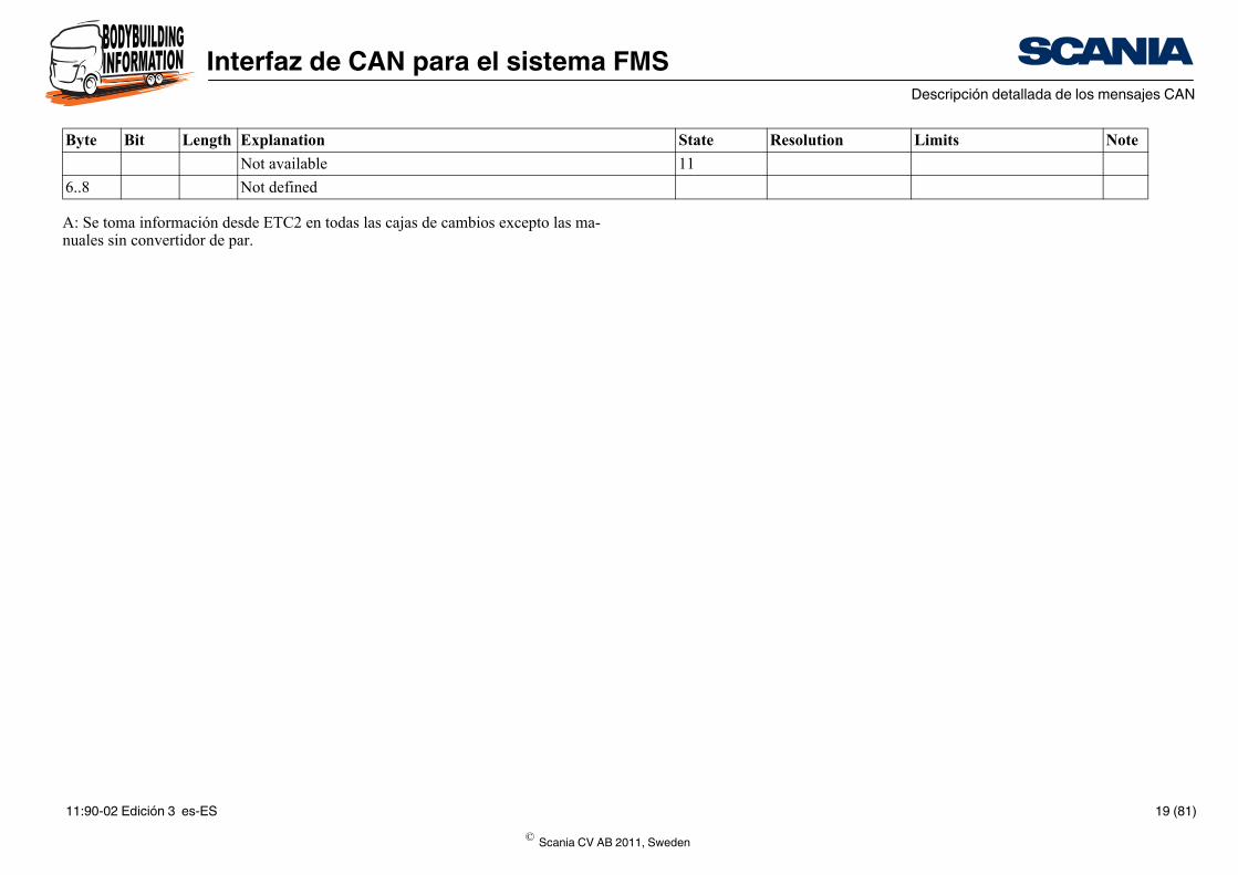
11
State Resolution Limits Note
A: Se toma información desde ETC2 en todas las cajas de cambios excepto las ma-nuales sin convertidor de par.
Not available
6..8 Not defined
Byte Bit Length Explanation
© Scania CV AB 2011, Sweden
11:90-02 Edición 3 es-ES 19 (81)
Interfaz de CAN para el sistema FMSDescripción detallada de los mensajes CAN
State Resolution Limits Note
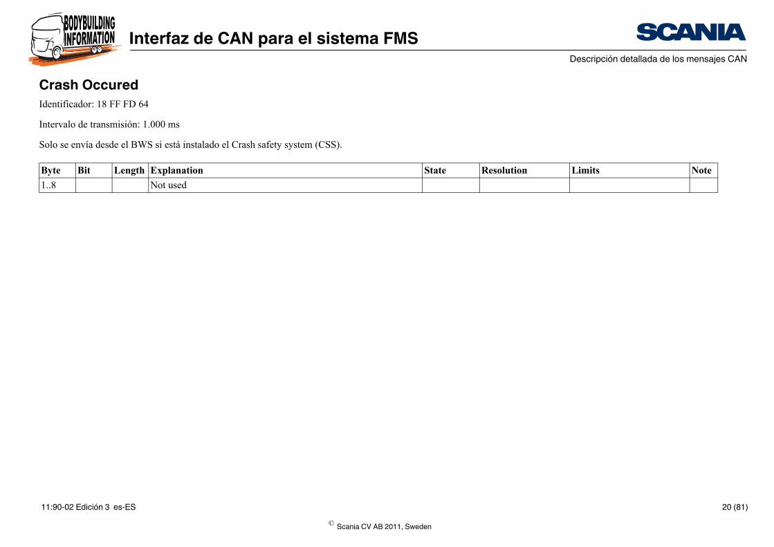
Crash OccuredIdentificador: 18 FF FD 64
Intervalo de transmisión: 1.000 ms
Solo se envía desde el BWS si está instalado el Crash safety system (CSS).
Byte Bit Length Explanation
1..8 Not used
© Scania CV AB 2011, Sweden
11:90-02 Edición 3 es-ES 20 (81)
Interfaz de CAN para el sistema FMSDescripción detallada de los mensajes CAN
State Resolution Limits Note
A
00
01
10
11
1/256 km/h por bit 0 a 251 km/h
FExx
FFxx
00
01
10
11
00
01
10
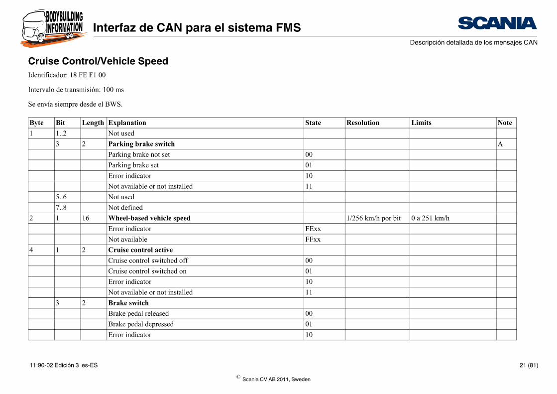
Cruise Control/Vehicle SpeedIdentificador: 18 FE F1 00
Intervalo de transmisión: 100 ms
Se envía siempre desde el BWS.
Byte Bit Length Explanation
1 1..2 Not used
3 2 Parking brake switch
Parking brake not set
Parking brake set
Error indicator
Not available or not installed
5..6 Not used
7..8 Not defined
2 1 16 Wheel-based vehicle speed
Error indicator
Not available
4 1 2 Cruise control active
Cruise control switched off
Cruise control switched on
Error indicator
Not available or not installed
3 2 Brake switch
Brake pedal released
Brake pedal depressed
Error indicator
© Scania CV AB 2011, Sweden
11:90-02 Edición 3 es-ES 21 (81)
Interfaz de CAN para el sistema FMSDescripción detallada de los mensajes CAN
11
00
01
10
11
00
01
10
11
00
01
10
11
00
01
10
11
00
01
10
11
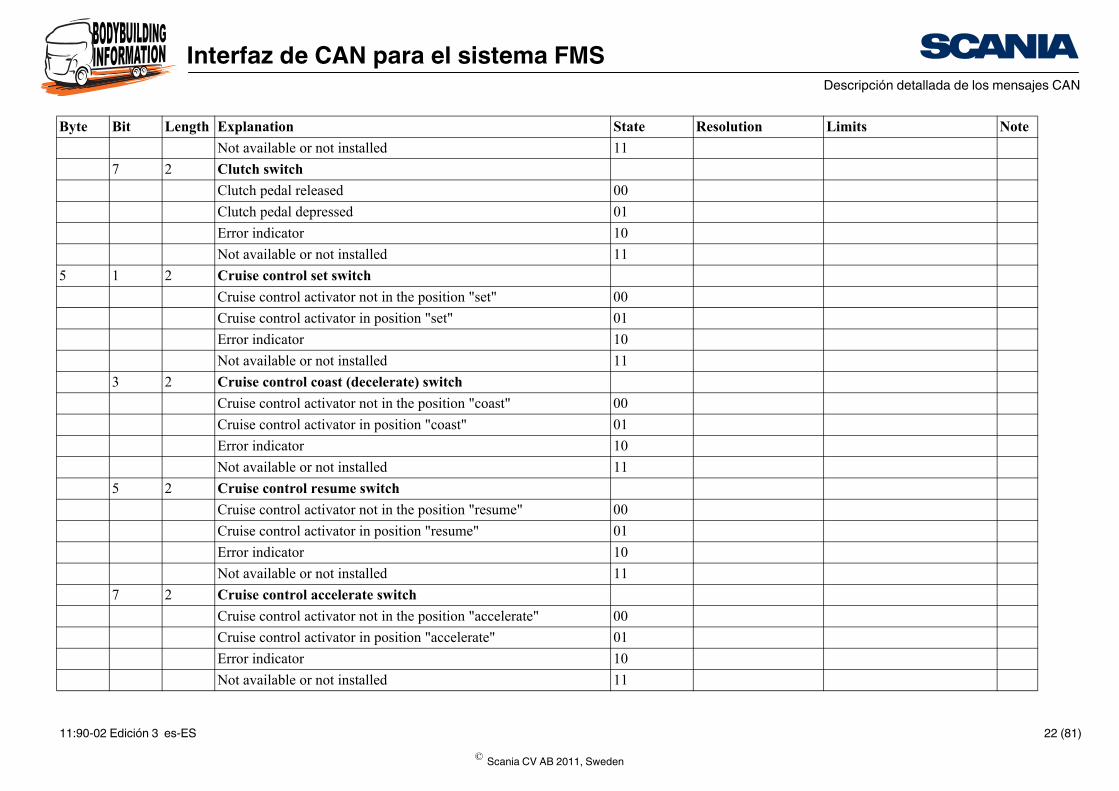
State Resolution Limits Note
Not available or not installed
7 2 Clutch switch
Clutch pedal released
Clutch pedal depressed
Error indicator
Not available or not installed
5 1 2 Cruise control set switch
Cruise control activator not in the position "set"
Cruise control activator in position "set"
Error indicator
Not available or not installed
3 2 Cruise control coast (decelerate) switch
Cruise control activator not in the position "coast"
Cruise control activator in position "coast"
Error indicator
Not available or not installed
5 2 Cruise control resume switch
Cruise control activator not in the position "resume"
Cruise control activator in position "resume"
Error indicator
Not available or not installed
7 2 Cruise control accelerate switch
Cruise control activator not in the position "accelerate"
Cruise control activator in position "accelerate"
Error indicator
Not available or not installed
Byte Bit Length Explanation
© Scania CV AB 2011, Sweden
11:90-02 Edición 3 es-ES 22 (81)
Interfaz de CAN para el sistema FMSDescripción detallada de los mensajes CAN
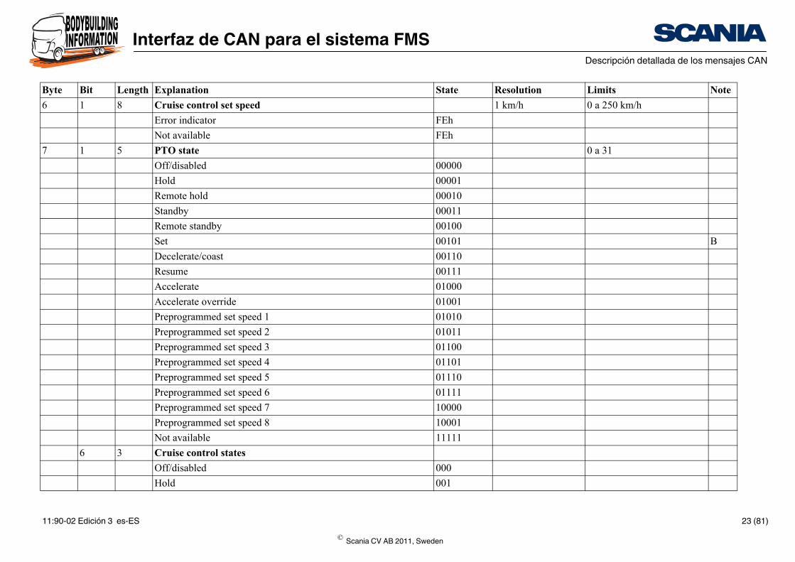
1 km/h 0 a 250 km/h
FEh
FEh
0 a 31
00000
00001
00010
00011
00100
00101 B
00110
00111
01000
01001
01010
01011
01100
01101
01110
01111
10000
10001
11111
000
001
State Resolution Limits Note
6 1 8 Cruise control set speed
Error indicator
Not available
7 1 5 PTO state
Off/disabled
Hold
Remote hold
Standby
Remote standby
Set
Decelerate/coast
Resume
Accelerate
Accelerate override
Preprogrammed set speed 1
Preprogrammed set speed 2
Preprogrammed set speed 3
Preprogrammed set speed 4
Preprogrammed set speed 5
Preprogrammed set speed 6
Preprogrammed set speed 7
Preprogrammed set speed 8
Not available
6 3 Cruise control states
Off/disabled
Hold
Byte Bit Length Explanation
© Scania CV AB 2011, Sweden
11:90-02 Edición 3 es-ES 23 (81)
Interfaz de CAN para el sistema FMSDescripción detallada de los mensajes CAN
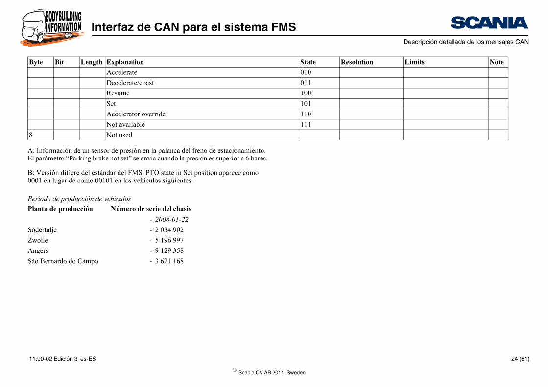
010
011
100
101
110
111
State Resolution Limits Note
A: Información de un sensor de presión en la palanca del freno de estacionamiento. El parámetro “Parking brake not set” se envía cuando la presión es superior a 6 bares.
B: Versión difiere del estándar del FMS. PTO state in Set position aparece como 0001 en lugar de como 00101 en los vehículos siguientes.
Accelerate
Decelerate/coast
Resume
Set
Accelerator override
Not available
8 Not used
Periodo de producción de vehículos
Planta de producción Número de serie del chasis
- 2008-01-22
Södertälje - 2 034 902
Zwolle - 5 196 997
Angers - 9 129 358
São Bernardo do Campo - 3 621 168
Byte Bit Length Explanation
© Scania CV AB 2011, Sweden
11:90-02 Edición 3 es-ES 24 (81)
Interfaz de CAN para el sistema FMSDescripción detallada de los mensajes CAN
State Resolution Limits Note
A
00
01
10
11
00
01
10
11
00
01
10
11
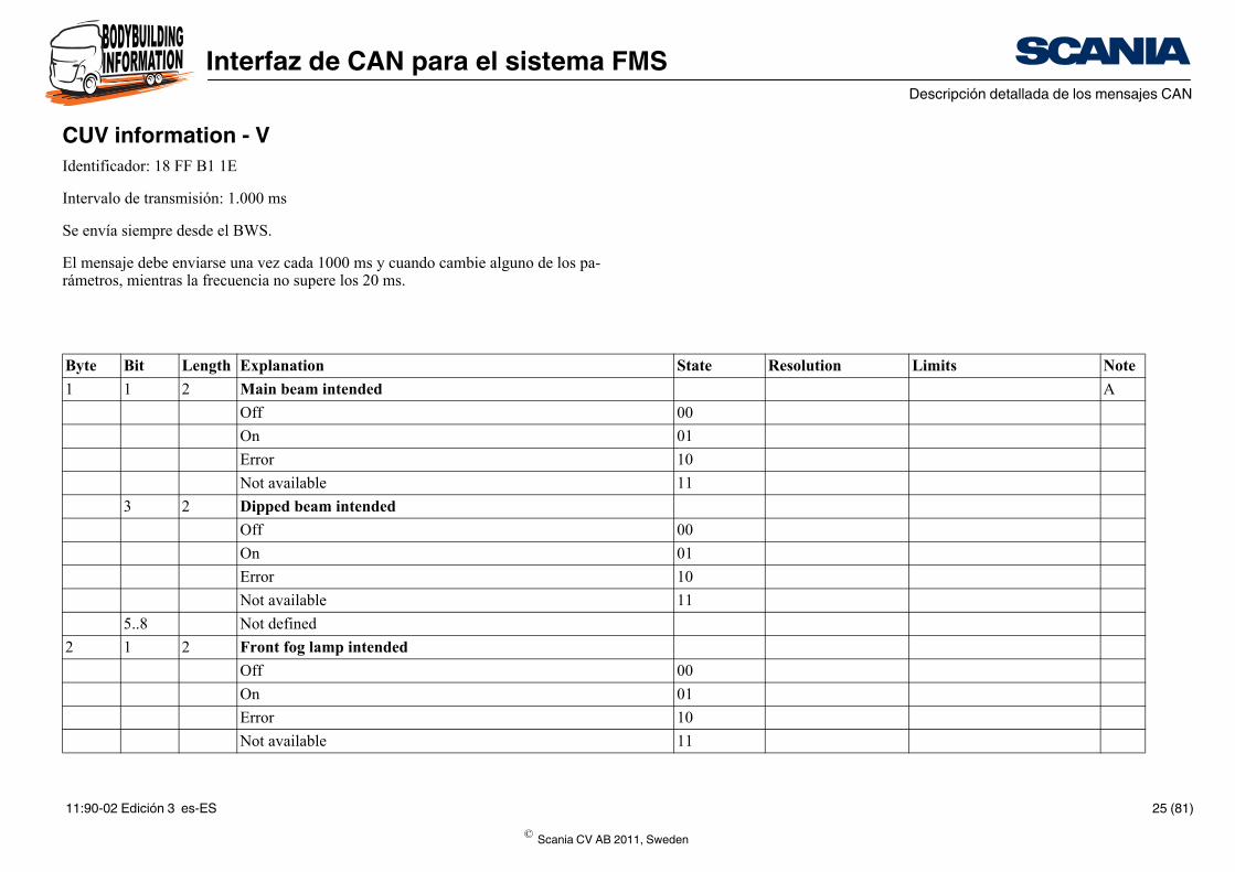
CUV information - VIdentificador: 18 FF B1 1E
Intervalo de transmisión: 1.000 ms
Se envía siempre desde el BWS.
El mensaje debe enviarse una vez cada 1000 ms y cuando cambie alguno de los pa-rámetros, mientras la frecuencia no supere los 20 ms.
Byte Bit Length Explanation
1 1 2 Main beam intended
Off
On
Error
Not available
3 2 Dipped beam intended
Off
On
Error
Not available
5..8 Not defined
2 1 2 Front fog lamp intended
Off
On
Error
Not available
© Scania CV AB 2011, Sweden
11:90-02 Edición 3 es-ES 25 (81)
Interfaz de CAN para el sistema FMSDescripción detallada de los mensajes CAN
00
01
10
11
00
01
10
11
00
01
10
11
00
01
10
11
00
01
10
11
State Resolution Limits Note
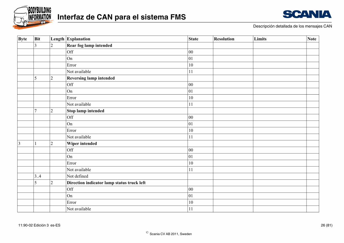
3 2 Rear fog lamp intended
Off
On
Error
Not available
5 2 Reversing lamp intended
Off
On
Error
Not available
7 2 Stop lamp intended
Off
On
Error
Not available
3 1 2 Wiper intended
Off
On
Error
Not available
3..4 Not defined
5 2 Direction indicator lamp status truck left
Off
On
Error
Not available
Byte Bit Length Explanation
© Scania CV AB 2011, Sweden
11:90-02 Edición 3 es-ES 26 (81)
Interfaz de CAN para el sistema FMSDescripción detallada de los mensajes CAN
00
01
10
11
00
01
10
11
00
01
10
11
00
01
10
11 B
00
01
10
11
State Resolution Limits Note
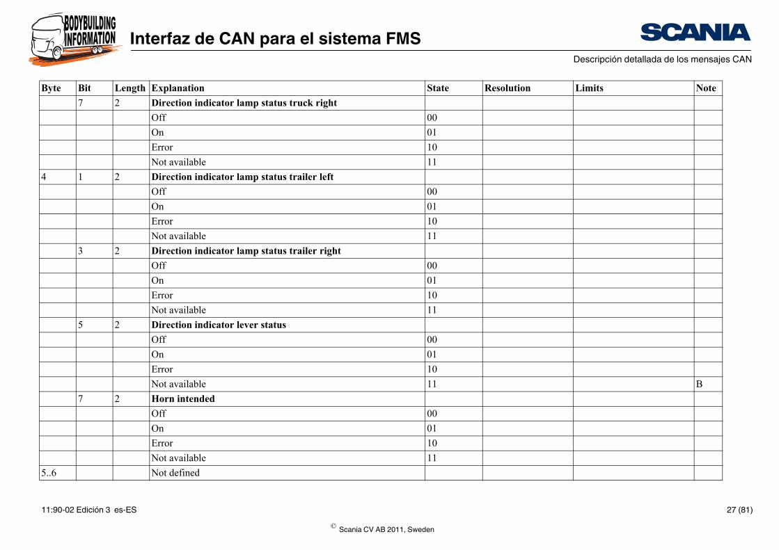
7 2 Direction indicator lamp status truck right
Off
On
Error
Not available
4 1 2 Direction indicator lamp status trailer left
Off
On
Error
Not available
3 2 Direction indicator lamp status trailer right
Off
On
Error
Not available
5 2 Direction indicator lever status
Off
On
Error
Not available
7 2 Horn intended
Off
On
Error
Not available
5..6 Not defined
Byte Bit Length Explanation
© Scania CV AB 2011, Sweden
11:90-02 Edición 3 es-ES 27 (81)
Interfaz de CAN para el sistema FMSDescripción detallada de los mensajes CAN
00
01
10
11
00
01
10
11
00
01
10
11
00
01
10
11
00
01
10
State Resolution Limits Note
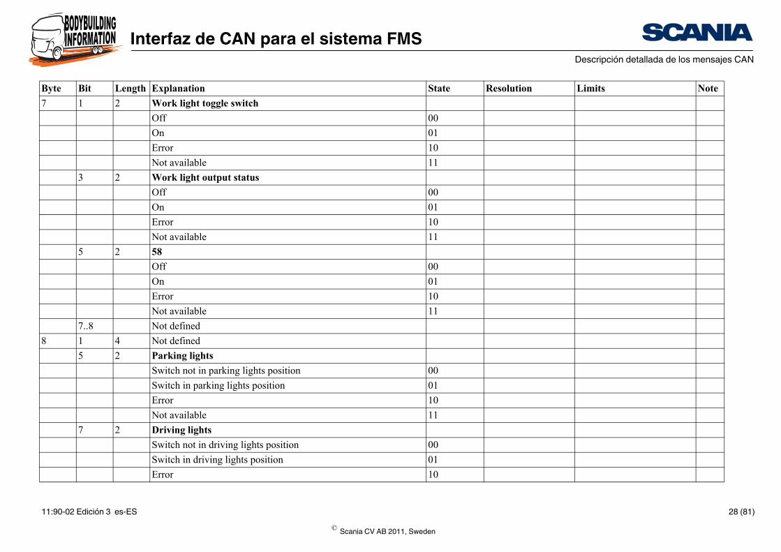
7 1 2 Work light toggle switch
Off
On
Error
Not available
3 2 Work light output status
Off
On
Error
Not available
5 2 58
Off
On
Error
Not available
7..8 Not defined
8 1 4 Not defined
5 2 Parking lights
Switch not in parking lights position
Switch in parking lights position
Error
Not available
7 2 Driving lights
Switch not in driving lights position
Switch in driving lights position
Error
Byte Bit Length Explanation
© Scania CV AB 2011, Sweden
11:90-02 Edición 3 es-ES 28 (81)
Interfaz de CAN para el sistema FMSDescripción detallada de los mensajes CAN
11
State Resolution Limits Note
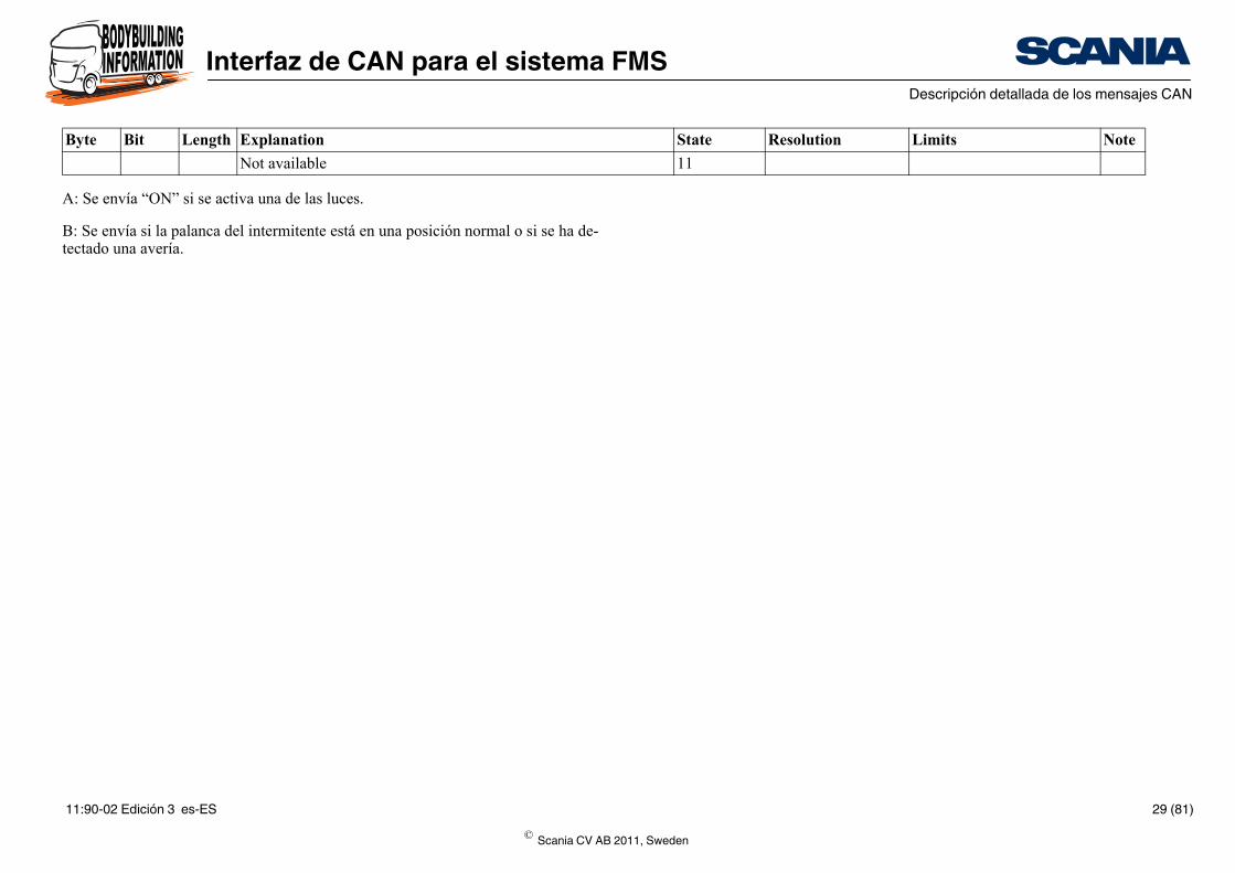
A: Se envía “ON” si se activa una de las luces.
B: Se envía si la palanca del intermitente está en una posición normal o si se ha de-tectado una avería.
Not available
Byte Bit Length Explanation
© Scania CV AB 2011, Sweden
11:90-02 Edición 3 es-ES 29 (81)
Interfaz de CAN para el sistema FMSDescripción detallada de los mensajes CAN
State Resolution Limits Note
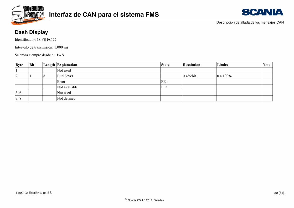
0.4%/bit 0 a 100%
FEh
FFh
Dash DisplayIdentificador: 18 FE FC 27
Intervalo de transmisión: 1.000 ms
Se envía siempre desde el BWS.
Byte Bit Length Explanation
1 Not used
2 1 8 Fuel level
Error
Not available
3..6 Not used
7..8 Not defined
© Scania CV AB 2011, Sweden
11:90-02 Edición 3 es-ES 30 (81)
Interfaz de CAN para el sistema FMSDescripción detallada de los mensajes CAN
State Resolution Limits Note
1 A
1 B
1 C
1 D
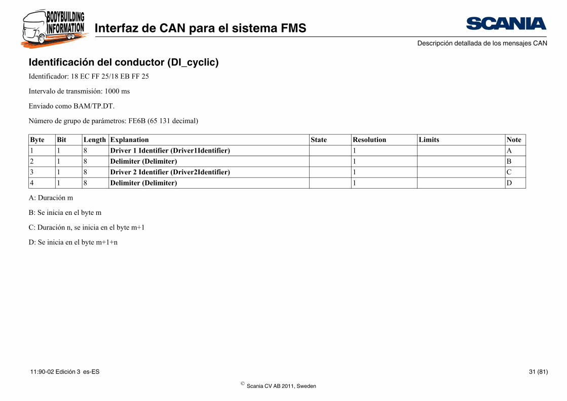
Identificación del conductor (DI_cyclic)Identificador: 18 EC FF 25/18 EB FF 25
Intervalo de transmisión: 1000 ms
Enviado como BAM/TP.DT.
Número de grupo de parámetros: FE6B (65 131 decimal)
A: Duración m
B: Se inicia en el byte m
C: Duración n, se inicia en el byte m+1
D: Se inicia en el byte m+1+n
Byte Bit Length Explanation
1 1 8 Driver 1 Identifier (Driver1Identifier)
2 1 8 Delimiter (Delimiter)
3 1 8 Driver 2 Identifier (Driver2Identifier)
4 1 8 Delimiter (Delimiter)
© Scania CV AB 2011, Sweden
11:90-02 Edición 3 es-ES 31 (81)
Interfaz de CAN para el sistema FMSDescripción detallada de los mensajes CAN
State Resolution Limits Note
1/256 kph 251 kph
FExx
FFxx
1/16 kph -7,8125 a +7,8125 kph
FE
FF
1/16 kph -7,8125 a +7,8125 kph
FE
FF
1/16 kph -7,8125 a +7,8125 kph
FE
FF
1/16 kph -7,8125 a +7,8125 kph
FE
FF
1/16 kph -7,8125 a +7,8125 kph
FE
FF
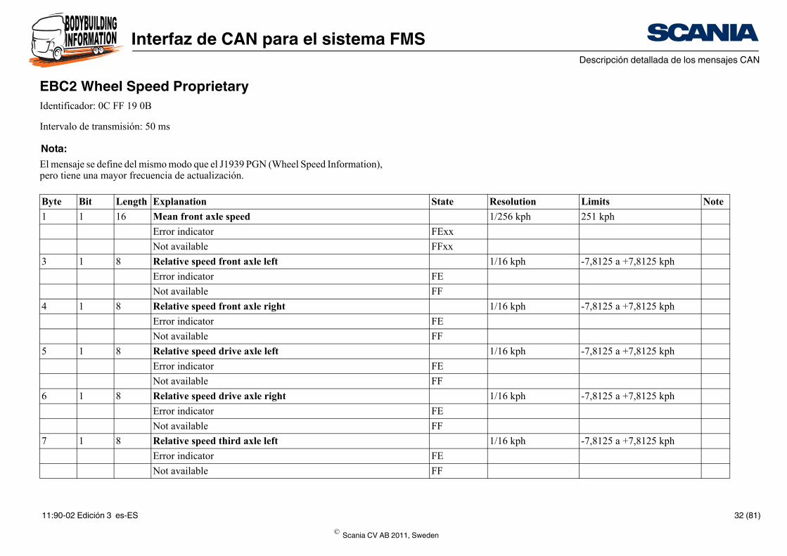
EBC2 Wheel Speed ProprietaryIdentificador: 0C FF 19 0B
Intervalo de transmisión: 50 ms
Nota:El mensaje se define del mismo modo que el J1939 PGN (Wheel Speed Information), pero tiene una mayor frecuencia de actualización.
Byte Bit Length Explanation
1 1 16 Mean front axle speed
Error indicator
Not available
3 1 8 Relative speed front axle left
Error indicator
Not available
4 1 8 Relative speed front axle right
Error indicator
Not available
5 1 8 Relative speed drive axle left
Error indicator
Not available
6 1 8 Relative speed drive axle right
Error indicator
Not available
7 1 8 Relative speed third axle left
Error indicator
Not available
© Scania CV AB 2011, Sweden
11:90-02 Edición 3 es-ES 32 (81)
Interfaz de CAN para el sistema FMSDescripción detallada de los mensajes CAN
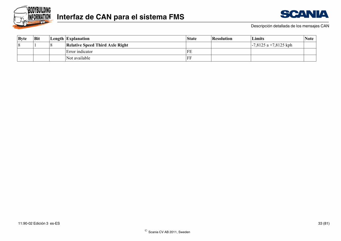
-7,8125 a +7,8125 kph
FE
FF
State Resolution Limits Note
8 1 8 Relative Speed Third Axle Right
Error indicator
Not available
Byte Bit Length Explanation
© Scania CV AB 2011, Sweden
11:90-02 Edición 3 es-ES 33 (81)
Interfaz de CAN para el sistema FMSDescripción detallada de los mensajes CAN
State Resolution Limits Note
00
01
11 A
00
01
11 A
00
01
11
00
01
10
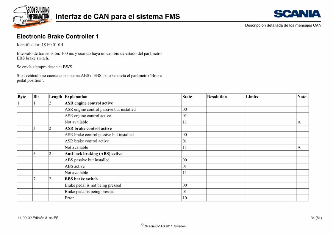
Electronic Brake Controller 1Identificador: 18 F0 01 0B
Intervalo de transmisión: 100 ms y cuando haya un cambio de estado del parámetro EBS brake switch.
Se envía siempre desde el BWS.
Si el vehículo no cuenta con sistema ABS o EBS, solo se envía el parámetro ’Brake pedal position’.
Byte Bit Length Explanation
1 1 2 ASR engine control active
ASR engine control passive but installed
ASR engine control active
Not available
3 2 ASR brake control active
ASR brake control passive but installed
ASR brake control active
Not available
5 2 Anti-lock braking (ABS) active
ABS passive but installed
ABS active
Not available
7 2 EBS brake switch
Brake pedal is not being pressed
Brake pedal is being pressed
Error
© Scania CV AB 2011, Sweden
11:90-02 Edición 3 es-ES 34 (81)
Interfaz de CAN para el sistema FMSDescripción detallada de los mensajes CAN
11
0.4%/bit 0 a 100%
FE
FF
B
00
01
10 C
B
00
01
10
00
01
10
11
00
01
10
11
00
01
10
State Resolution Limits Note
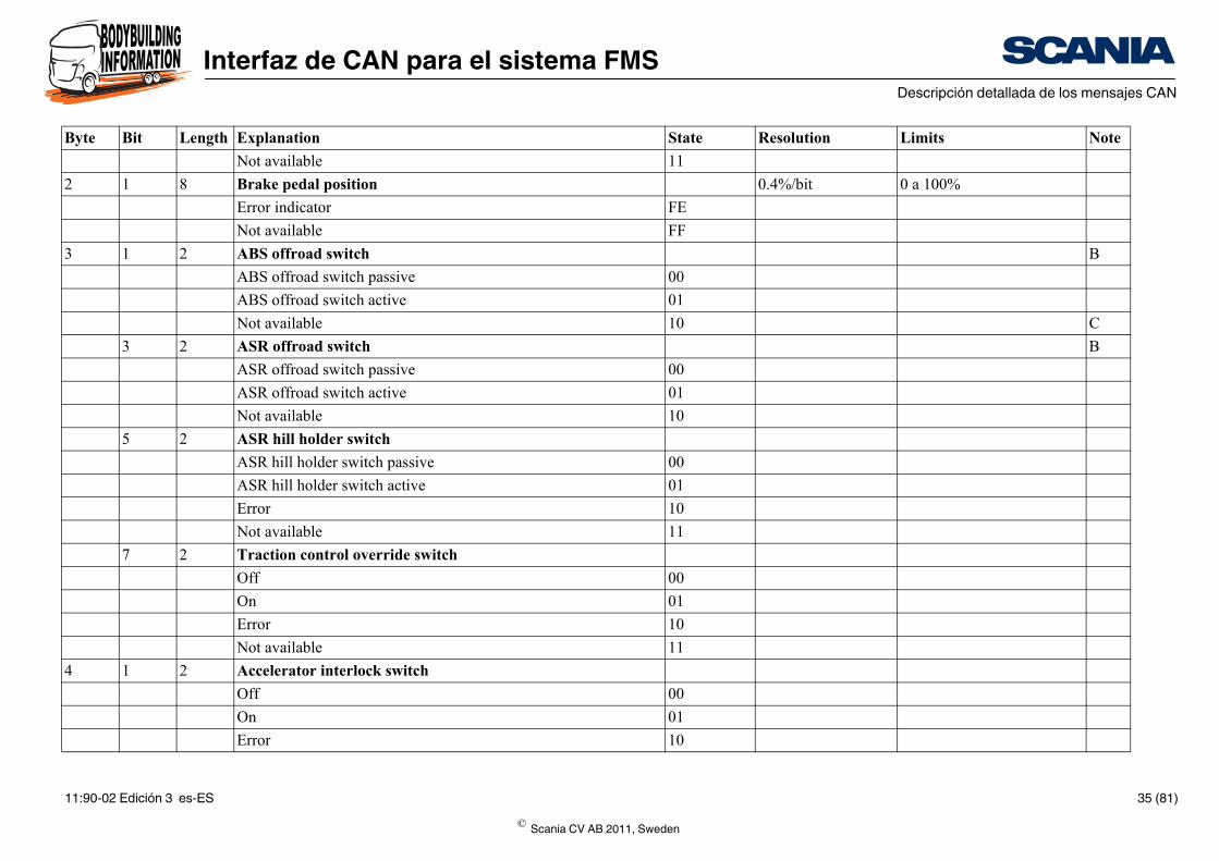
Not available
2 1 8 Brake pedal position
Error indicator
Not available
3 1 2 ABS offroad switch
ABS offroad switch passive
ABS offroad switch active
Not available
3 2 ASR offroad switch
ASR offroad switch passive
ASR offroad switch active
Not available
5 2 ASR hill holder switch
ASR hill holder switch passive
ASR hill holder switch active
Error
Not available
7 2 Traction control override switch
Off
On
Error
Not available
4 1 2 Accelerator interlock switch
Off
On
Error
Byte Bit Length Explanation
© Scania CV AB 2011, Sweden
11:90-02 Edición 3 es-ES 35 (81)
Interfaz de CAN para el sistema FMSDescripción detallada de los mensajes CAN
11
00
01
10
11
00
01
10
11
00
01
10
11
10
11
00
01
D
00
01
State Resolution Limits Note
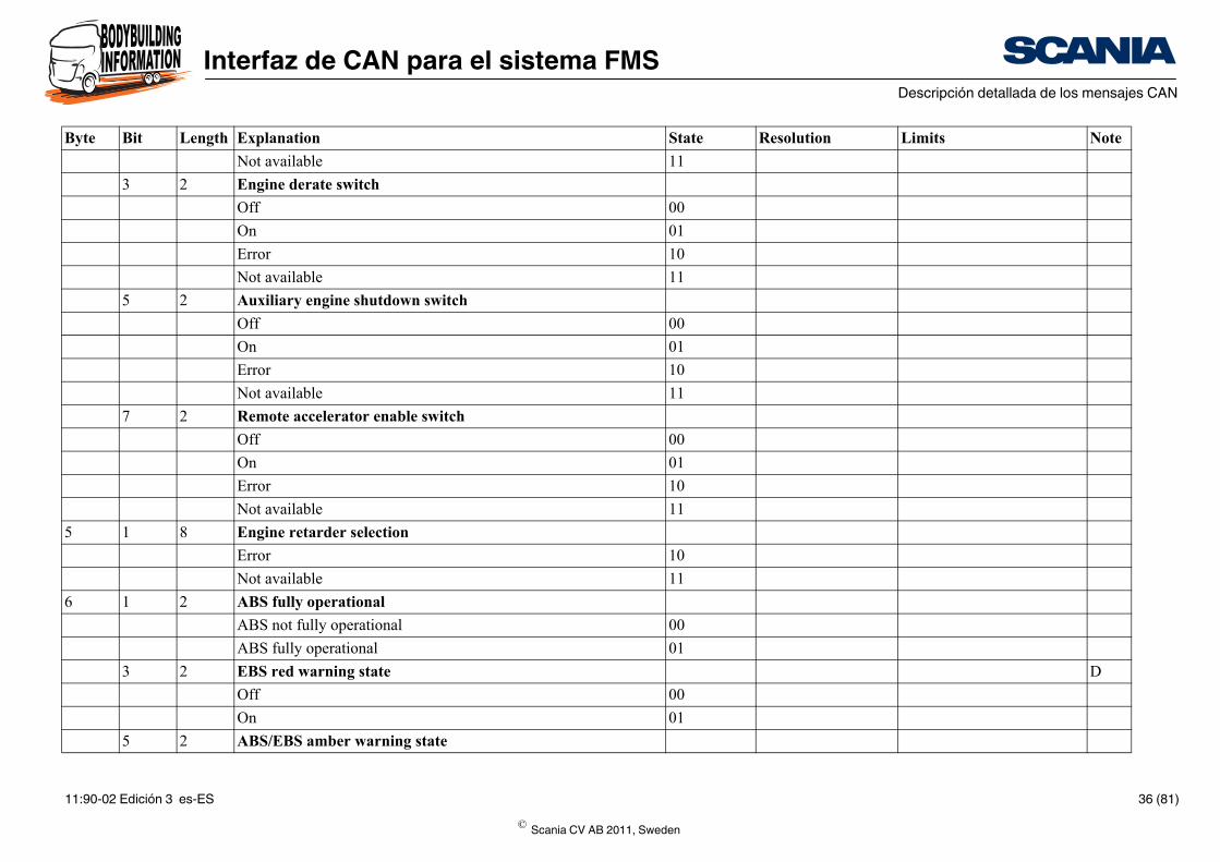
Not available
3 2 Engine derate switch
Off
On
Error
Not available
5 2 Auxiliary engine shutdown switch
Off
On
Error
Not available
7 2 Remote accelerator enable switch
Off
On
Error
Not available
5 1 8 Engine retarder selection
Error
Not available
6 1 2 ABS fully operational
ABS not fully operational
ABS fully operational
3 2 EBS red warning state
Off
On
5 2 ABS/EBS amber warning state
Byte Bit Length Explanation
© Scania CV AB 2011, Sweden
11:90-02 Edición 3 es-ES 36 (81)
Interfaz de CAN para el sistema FMSDescripción detallada de los mensajes CAN
00
01
11
00
01
10
11
0 a 250 E
FEh
FFh
00
01
10
11
00
01
10
11
00
01
10
State Resolution Limits Note
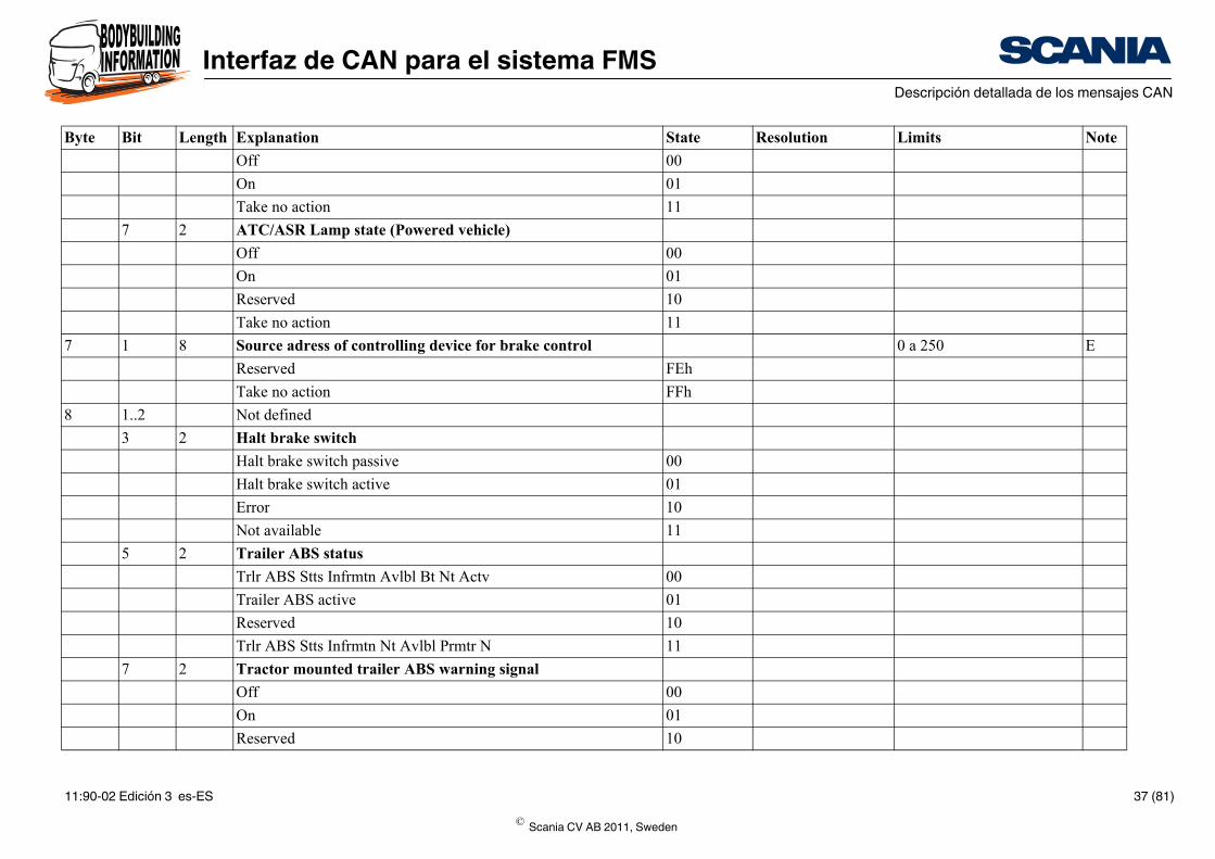
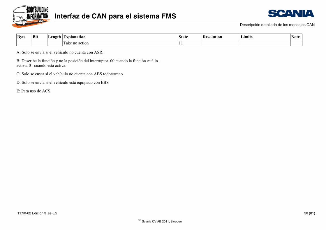
Off
On
Take no action
7 2 ATC/ASR Lamp state (Powered vehicle)
Off
On
Reserved
Take no action
7 1 8 Source adress of controlling device for brake control
Reserved
Take no action
8 1..2 Not defined
3 2 Halt brake switch
Halt brake switch passive
Halt brake switch active
Error
Not available
5 2 Trailer ABS status
Trlr ABS Stts Infrmtn Avlbl Bt Nt Actv
Trailer ABS active
Reserved
Trlr ABS Stts Infrmtn Nt Avlbl Prmtr N
7 2 Tractor mounted trailer ABS warning signal
Off
On
Reserved
Byte Bit Length Explanation
© Scania CV AB 2011, Sweden
11:90-02 Edición 3 es-ES 37 (81)
Interfaz de CAN para el sistema FMSDescripción detallada de los mensajes CAN
11
State Resolution Limits Note
A: Solo se envía si el vehículo no cuenta con ASR.
B: Describe la función y no la posición del interruptor. 00 cuando la función está in-activa, 01 cuando está activa.
C: Solo se envía si el vehículo no cuenta con ABS todoterreno.
D: Solo se envía si el vehículo está equipado con EBS
E: Para uso de ACS.
Take no action
Byte Bit Length Explanation
© Scania CV AB 2011, Sweden
11:90-02 Edición 3 es-ES 38 (81)
Interfaz de CAN para el sistema FMSDescripción detallada de los mensajes CAN
State Resolution Limits Note
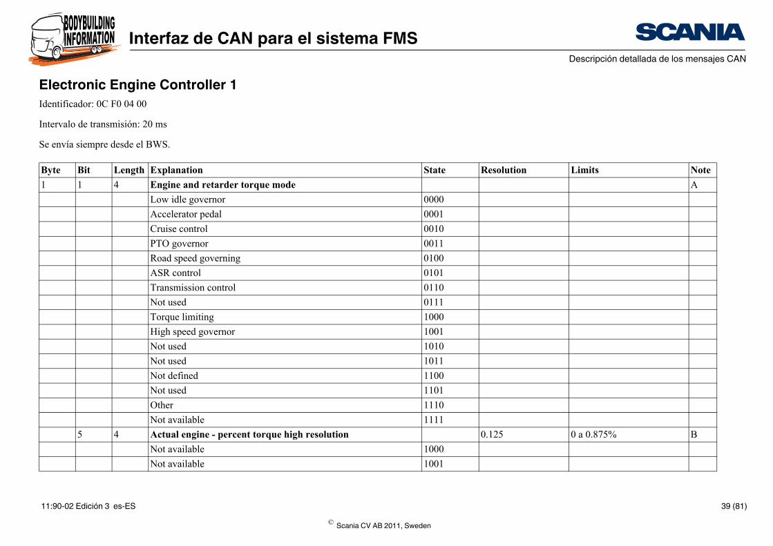
A
0000
0001
0010
0011
0100
0101
0110
0111
1000
1001
1010
1011
1100
1101
1110
1111
0.125 0 a 0.875% B
1000
1001
Electronic Engine Controller 1Identificador: 0C F0 04 00
Intervalo de transmisión: 20 ms
Se envía siempre desde el BWS.
Byte Bit Length Explanation
1 1 4 Engine and retarder torque mode
Low idle governor
Accelerator pedal
Cruise control
PTO governor
Road speed governing
ASR control
Transmission control
Not used
Torque limiting
High speed governor
Not used
Not used
Not defined
Not used
Other
Not available
5 4 Actual engine - percent torque high resolution
Not available
Not available
© Scania CV AB 2011, Sweden
11:90-02 Edición 3 es-ES 39 (81)
Interfaz de CAN para el sistema FMSDescripción detallada de los mensajes CAN
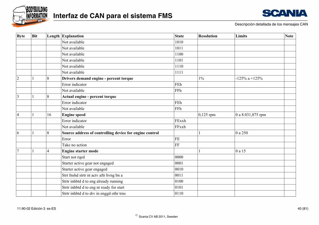
1010
1011
1100
1101
1110
1111
1% -125% a +125%
FEh
FFh
FEh
FFh
0,125 rpm 0 a 8.031,875 rpm
FExxh
FFxxh
1 0 a 250
FE
FF
1 0 a 15
0000
0001
0010
0011
0100
0101
0110
State Resolution Limits Note
Not available
Not available
Not available
Not available
Not available
Not available
2 1 8 Drivers demand engine - percent torque
Error indicator
Not available
3 1 8 Actual engine - percent torque
Error indicator
Not available
4 1 16 Engine speed
Error indicator
Not available
6 1 8 Source address of controlling device for engine control
Error
Take no action
7 1 4 Engine starter mode
Start not rqed
Starter active gear not engaged
Starter active gear engaged
Strt fnshd strtr nt actv aftr hvng bn a
Strtr inhbtd d to eng already running
Strtr inhbtd d to eng nt ready for start
Strtr inhbtd d to drv in enggd othr trns
Byte Bit Length Explanation
© Scania CV AB 2011, Sweden
11:90-02 Edición 3 es-ES 40 (81)
Interfaz de CAN para el sistema FMSDescripción detallada de los mensajes CAN
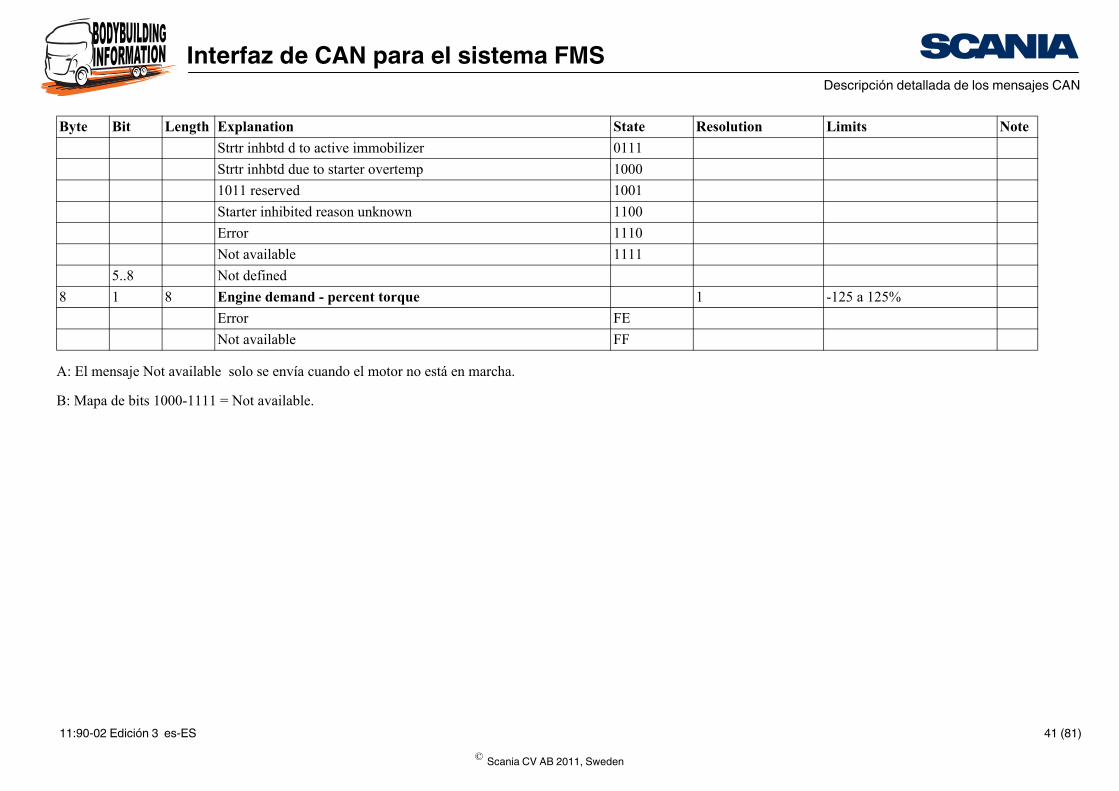
0111
1000
1001
1100
1110
1111
1 -125 a 125%
FE
FF
State Resolution Limits Note
A: El mensaje Not available solo se envía cuando el motor no está en marcha.
B: Mapa de bits 1000-1111 = Not available.
Strtr inhbtd d to active immobilizer
Strtr inhbtd due to starter overtemp
1011 reserved
Starter inhibited reason unknown
Error
Not available
5..8 Not defined
8 1 8 Engine demand - percent torque
Error
Not available
Byte Bit Length Explanation
© Scania CV AB 2011, Sweden
11:90-02 Edición 3 es-ES 41 (81)
Interfaz de CAN para el sistema FMSDescripción detallada de los mensajes CAN
State Resolution Limits Note
00
01
10
11
00
01
10
11
00
01
00
01
10
11
0.4% 0 a 100%
FE
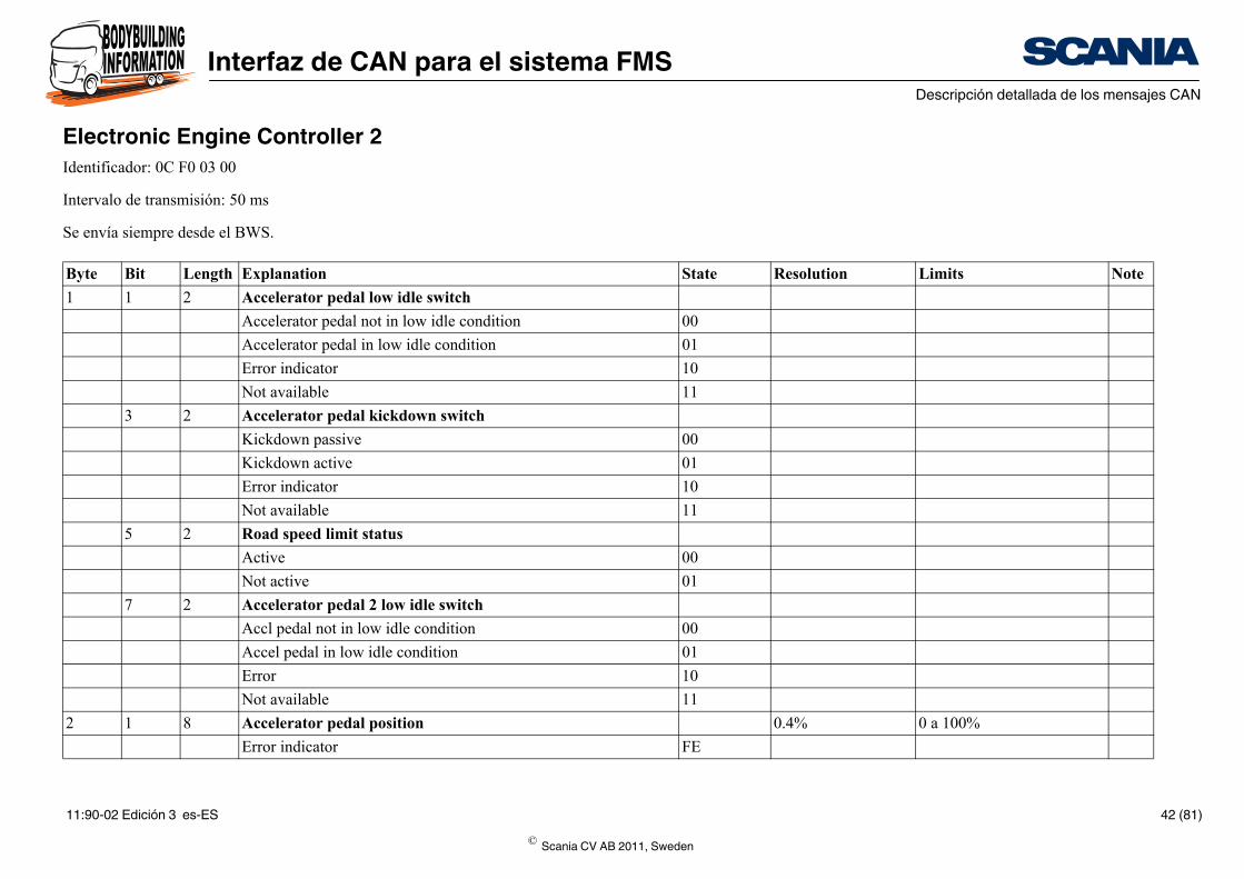
Electronic Engine Controller 2Identificador: 0C F0 03 00
Intervalo de transmisión: 50 ms
Se envía siempre desde el BWS.
Byte Bit Length Explanation
1 1 2 Accelerator pedal low idle switch
Accelerator pedal not in low idle condition
Accelerator pedal in low idle condition
Error indicator
Not available
3 2 Accelerator pedal kickdown switch
Kickdown passive
Kickdown active
Error indicator
Not available
5 2 Road speed limit status
Active
Not active
7 2 Accelerator pedal 2 low idle switch
Accl pedal not in low idle condition
Accel pedal in low idle condition
Error
Not available
2 1 8 Accelerator pedal position
Error indicator
© Scania CV AB 2011, Sweden
11:90-02 Edición 3 es-ES 42 (81)
Interfaz de CAN para el sistema FMSDescripción detallada de los mensajes CAN
FF
1% 0 a 125%
FE
FF
0.4% 0 a 100%
FE
FF
0.4% 0 a 100%
00
01
10
11
State Resolution Limits Note
Not available
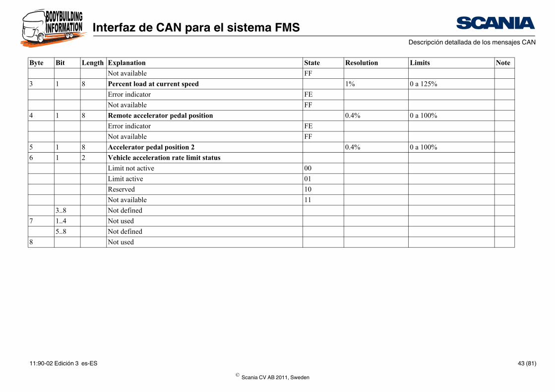
3 1 8 Percent load at current speed
Error indicator
Not available
4 1 8 Remote accelerator pedal position
Error indicator
Not available
5 1 8 Accelerator pedal position 2
6 1 2 Vehicle acceleration rate limit status
Limit not active
Limit active
Reserved
Not available
3..8 Not defined
7 1..4 Not used
5..8 Not defined
8 Not used
Byte Bit Length Explanation
© Scania CV AB 2011, Sweden
11:90-02 Edición 3 es-ES 43 (81)
Interfaz de CAN para el sistema FMSDescripción detallada de los mensajes CAN
State Resolution Limits Note
1 0 - 15 A
0000
0001
0010
0011
0100
0101
0110
0111
1000
1001
1010
1011
1100
1101
1110
1111
00
01
10
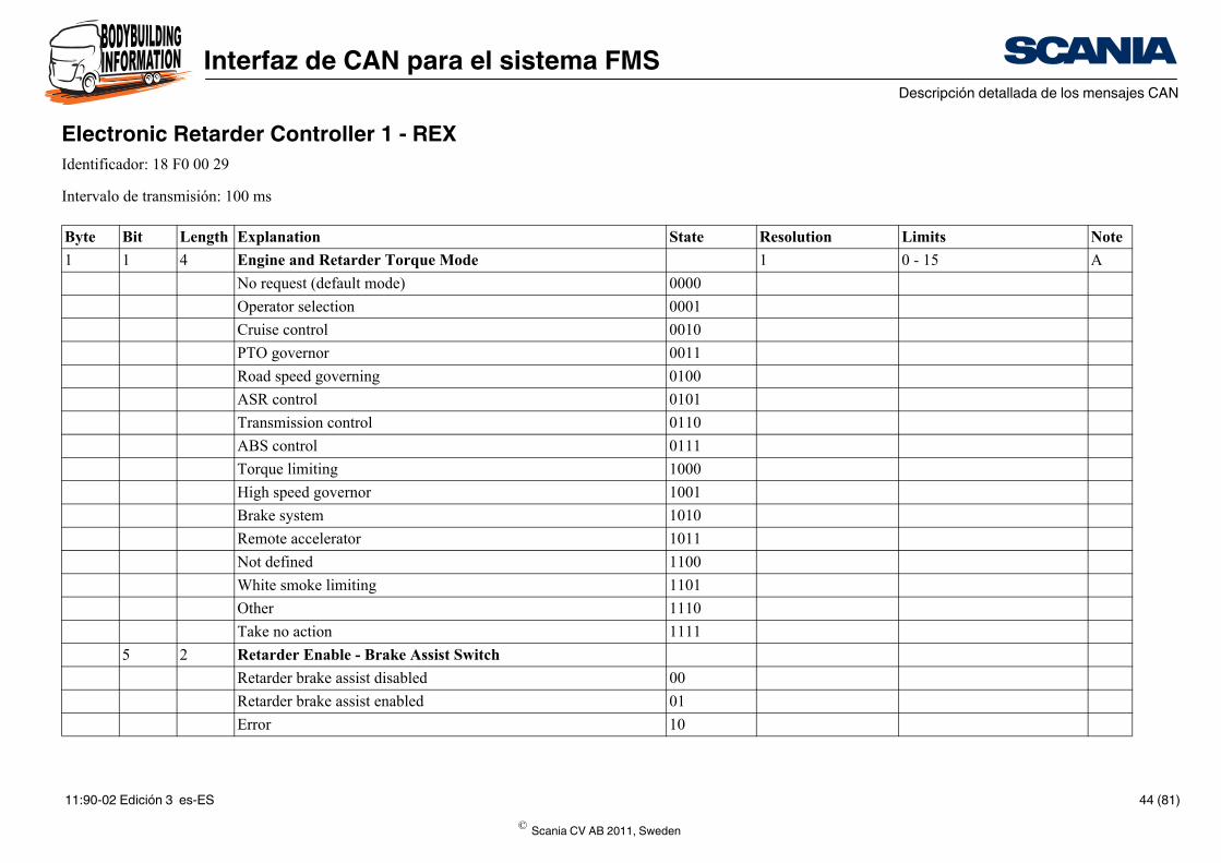
Electronic Retarder Controller 1 - REXIdentificador: 18 F0 00 29
Intervalo de transmisión: 100 ms
Byte Bit Length Explanation
1 1 4 Engine and Retarder Torque Mode
No request (default mode)
Operator selection
Cruise control
PTO governor
Road speed governing
ASR control
Transmission control
ABS control
Torque limiting
High speed governor
Brake system
Remote accelerator
Not defined
White smoke limiting
Other
Take no action
5 2 Retarder Enable - Brake Assist Switch
Retarder brake assist disabled
Retarder brake assist enabled
Error
© Scania CV AB 2011, Sweden
11:90-02 Edición 3 es-ES 44 (81)
Interfaz de CAN para el sistema FMSDescripción detallada de los mensajes CAN
11
00
01
10
11
-125 - 125% B
FE
FF
-125 - 125%
FE
FF
00
01
10
11
00
01
10
11
00
State Resolution Limits Note
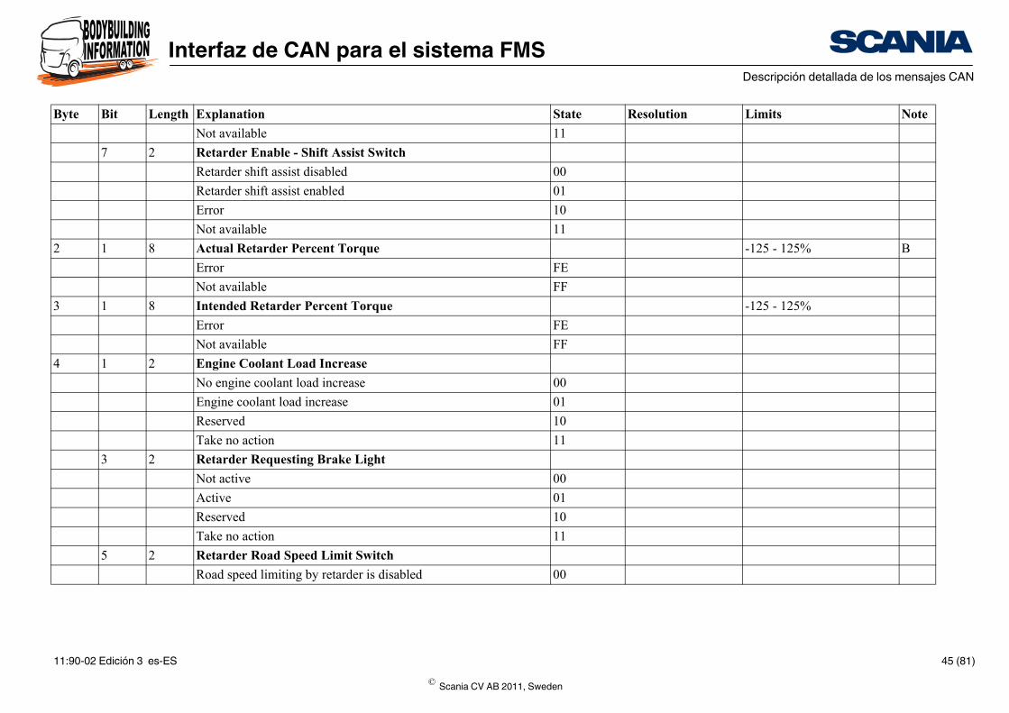
Not available
7 2 Retarder Enable - Shift Assist Switch
Retarder shift assist disabled
Retarder shift assist enabled
Error
Not available
2 1 8 Actual Retarder Percent Torque
Error
Not available
3 1 8 Intended Retarder Percent Torque
Error
Not available
4 1 2 Engine Coolant Load Increase
No engine coolant load increase
Engine coolant load increase
Reserved
Take no action
3 2 Retarder Requesting Brake Light
Not active
Active
Reserved
Take no action
5 2 Retarder Road Speed Limit Switch
Road speed limiting by retarder is disabled
Byte Bit Length Explanation
© Scania CV AB 2011, Sweden
11:90-02 Edición 3 es-ES 45 (81)
Interfaz de CAN para el sistema FMSDescripción detallada de los mensajes CAN
that the itions
01
10
11
00
that the sitions
01
10
11
ntrol 0 - 253
FE
FF
-125 - 125%
0.4 0 - 100%
-125 - 125%
State Resolution Limits Note
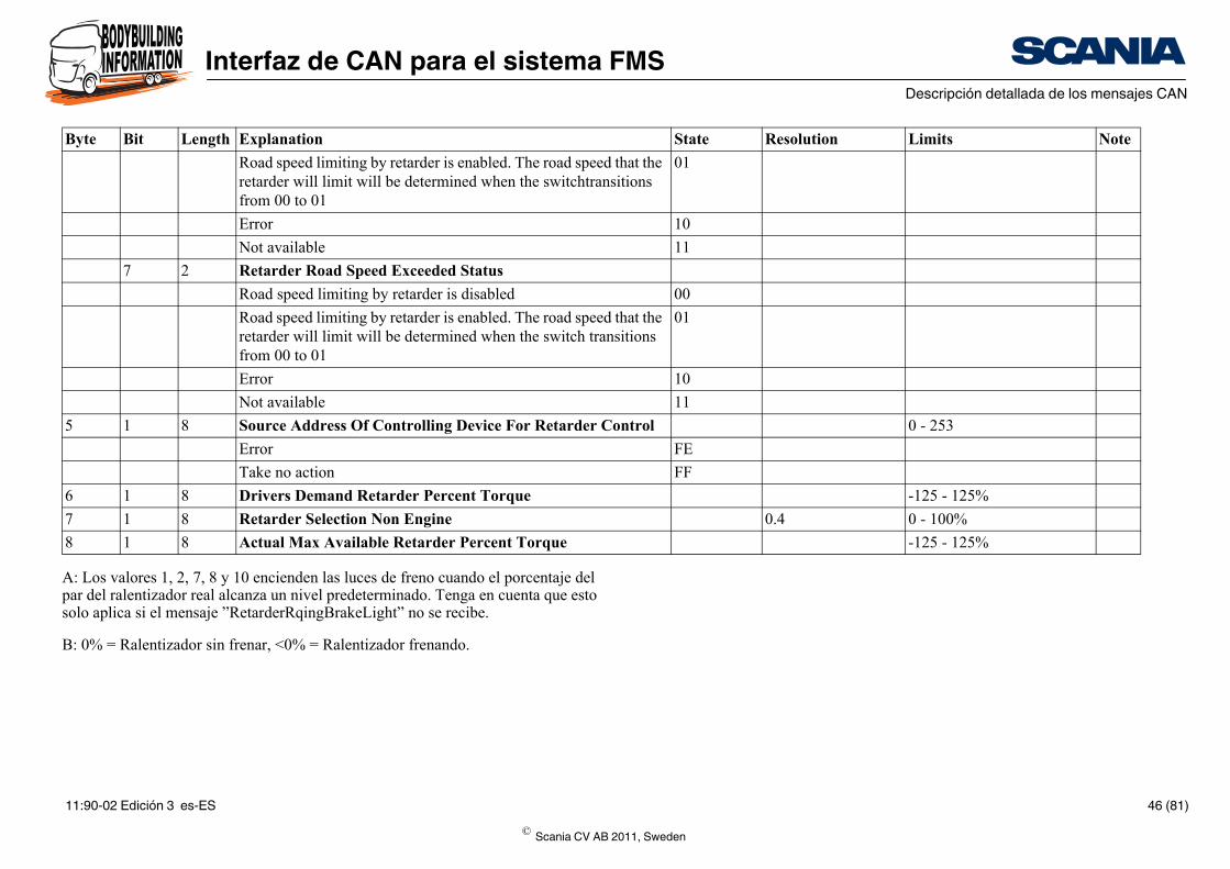
A: Los valores 1, 2, 7, 8 y 10 encienden las luces de freno cuando el porcentaje del par del ralentizador real alcanza un nivel predeterminado. Tenga en cuenta que esto solo aplica si el mensaje ”RetarderRqingBrakeLight” no se recibe.
B: 0% = Ralentizador sin frenar, <0% = Ralentizador frenando.
Road speed limiting by retarder is enabled. The road speed retarder will limit will be determined when the switchtransfrom 00 to 01
Error
Not available
7 2 Retarder Road Speed Exceeded Status
Road speed limiting by retarder is disabled
Road speed limiting by retarder is enabled. The road speed retarder will limit will be determined when the switch tranfrom 00 to 01
Error
Not available
5 1 8 Source Address Of Controlling Device For Retarder Co
Error
Take no action
6 1 8 Drivers Demand Retarder Percent Torque
7 1 8 Retarder Selection Non Engine
8 1 8 Actual Max Available Retarder Percent Torque
Byte Bit Length Explanation
© Scania CV AB 2011, Sweden
11:90-02 Edición 3 es-ES 46 (81)
Interfaz de CAN para el sistema FMSDescripción detallada de los mensajes CAN
State Resolution Limits Note
0000
0001 A
0010
0011
0100
0101
0110
0111
1000
1001
1010
1011
1100
1101
1110
1111 B
00
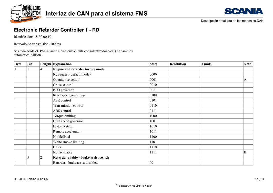
Electronic Retarder Controller 1 - RDIdentificador: 18 F0 00 10
Intervalo de transmisión: 100 ms
Se envía desde el BWS cuando el vehículo cuenta con ralentizador o caja de cambios automática Allison.
Byte Bit Length Explanation
1 1 4 Engine and retarder torque mode
No request (default mode)
Operator selection
Cruise control
PTO governor
Road speed governing
ASR control
Transmission control
ABS control
Torque limiting
High speed governor
Brake system
Remote accelerator
Not defined
White smoke limiting
Other
Not available
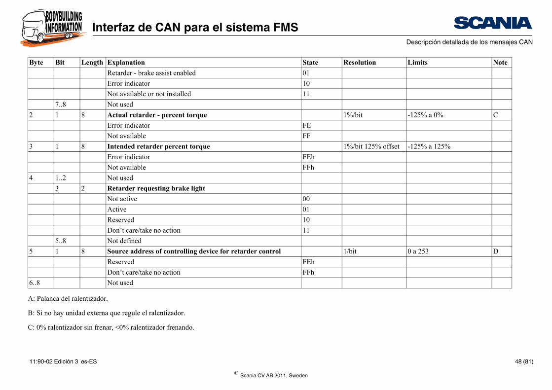
5 2 Retarder enable - brake assist switch
Retarder - brake assist disabled
© Scania CV AB 2011, Sweden
11:90-02 Edición 3 es-ES 47 (81)
Interfaz de CAN para el sistema FMSDescripción detallada de los mensajes CAN
01
10
11
1%/bit -125% a 0% C
FE
FF
1%/bit 125% offset -125% a 125%
FEh
FFh
00
01
10
11
l 1/bit 0 a 253 D
FEh
FFh
State Resolution Limits Note
A: Palanca del ralentizador.
B: Si no hay unidad externa que regule el ralentizador.
C: 0% ralentizador sin frenar, <0% ralentizador frenando.
Retarder - brake assist enabled
Error indicator
Not available or not installed
7..8 Not used
2 1 8 Actual retarder - percent torque
Error indicator
Not available
3 1 8 Intended retarder percent torque
Error indicator
Not available
4 1..2 Not used
3 2 Retarder requesting brake light
Not active
Active
Reserved
Don’t care/take no action
5..8 Not defined
5 1 8 Source address of controlling device for retarder contro
Reserved
Don’t care/take no action
6..8 Not used
Byte Bit Length Explanation
© Scania CV AB 2011, Sweden
11:90-02 Edición 3 es-ES 48 (81)
Interfaz de CAN para el sistema FMSDescripción detallada de los mensajes CAN
D: La dirección de origen nº 10 se envía cuando el ralentizador no funciona bajo el control de una unidad de mando externa.
© Scania CV AB 2011, Sweden
11:90-02 Edición 3 es-ES 49 (81)
Interfaz de CAN para el sistema FMSDescripción detallada de los mensajes CAN
State Resolution Limits Note
1 marcha -125 a +125
FE
FF
0.001 0 a 64 255
FExx
FFxx
1 marcha -125 a +125
FE
FF
ASCII 0 a 255 A
FExx
FFxx
ASCII 0 a 255 A
FExx
FFxx
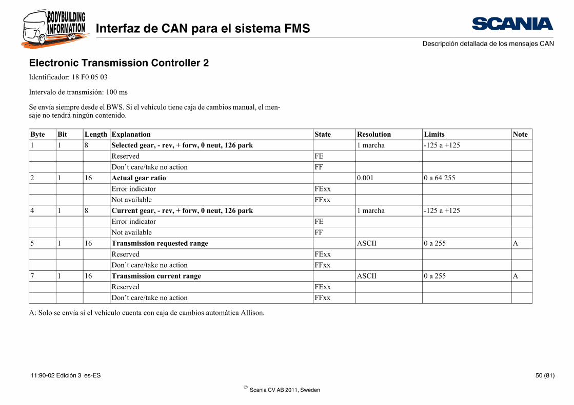
Electronic Transmission Controller 2Identificador: 18 F0 05 03
Intervalo de transmisión: 100 ms
Se envía siempre desde el BWS. Si el vehículo tiene caja de cambios manual, el men-saje no tendrá ningún contenido.
A: Solo se envía si el vehículo cuenta con caja de cambios automática Allison.
Byte Bit Length Explanation
1 1 8 Selected gear, - rev, + forw, 0 neut, 126 park
Reserved
Don’t care/take no action
2 1 16 Actual gear ratio
Error indicator
Not available
4 1 8 Current gear, - rev, + forw, 0 neut, 126 park
Error indicator
Not available
5 1 16 Transmission requested range
Reserved
Don’t care/take no action
7 1 16 Transmission current range
Reserved
Don’t care/take no action
© Scania CV AB 2011, Sweden
11:90-02 Edición 3 es-ES 50 (81)
Interfaz de CAN para el sistema FMSDescripción detallada de los mensajes CAN
State Resolution Limits Note
0,125 rpm 0 a 8.031,875 rpm
FExx
FFxx
1% -125% a +125%
FE
FF
0,125 rpm 0 a 8.031,875 rpm
FExx
FFxx
1% -125% a +125%
FE
FF
0,125 rpm 0 a 8.031,875 rpm
FExx
FFxx
1% -125% a +125%
FE
FF
0,125 rpm 0 a 8.031,875 rpm
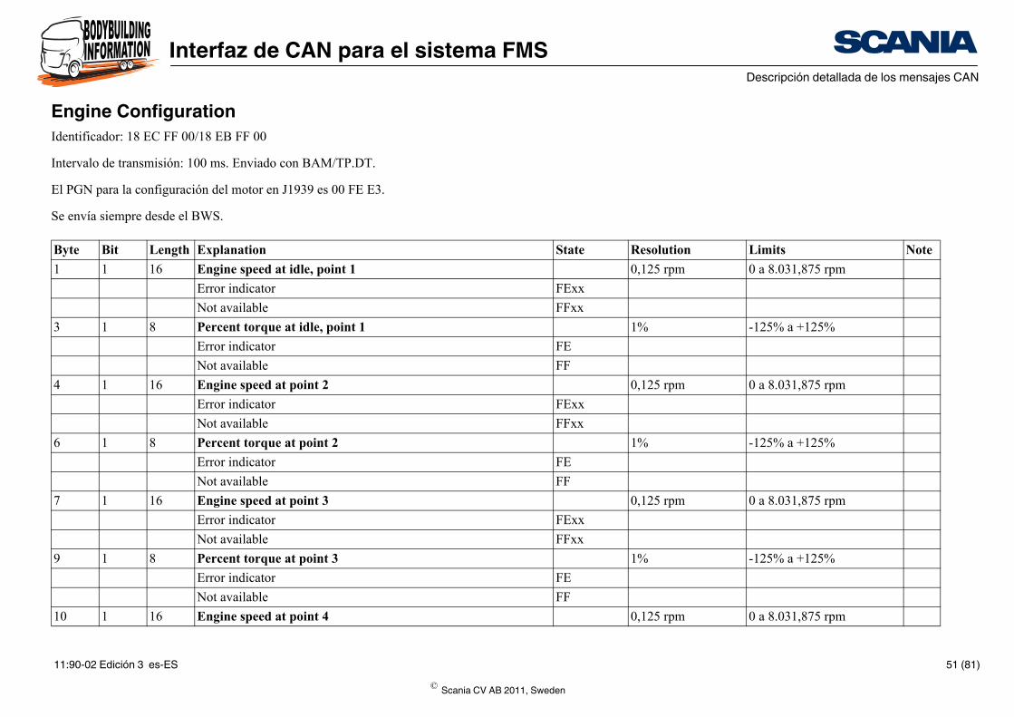
Engine ConfigurationIdentificador: 18 EC FF 00/18 EB FF 00
Intervalo de transmisión: 100 ms. Enviado con BAM/TP.DT.
El PGN para la configuración del motor en J1939 es 00 FE E3.
Se envía siempre desde el BWS.
Byte Bit Length Explanation
1 1 16 Engine speed at idle, point 1
Error indicator
Not available
3 1 8 Percent torque at idle, point 1
Error indicator
Not available
4 1 16 Engine speed at point 2
Error indicator
Not available
6 1 8 Percent torque at point 2
Error indicator
Not available
7 1 16 Engine speed at point 3
Error indicator
Not available
9 1 8 Percent torque at point 3
Error indicator
Not available
10 1 16 Engine speed at point 4
© Scania CV AB 2011, Sweden
11:90-02 Edición 3 es-ES 51 (81)
Interfaz de CAN para el sistema FMSDescripción detallada de los mensajes CAN
FExx
FFxx
1% -125% a +125%
FE
FF
0,125 rpm 0 a 8.031,875 rpm
FExx
FFxx
1% -125% a +125%
FE
FF
0,125 rpm 0 a 8.031,875 rpm
FExx
FFxx
1 Nm 0 a 64 255 Nm
FExx
FFxx
0,125 rpm 0 a 8.031,875 rpm
FExx
FFxx
0,1 s 0 a 25 s
FE
FF
10 rpm 0 a 2500 rpm
FE
FF
State Resolution Limits Note
Error indicator
Not available
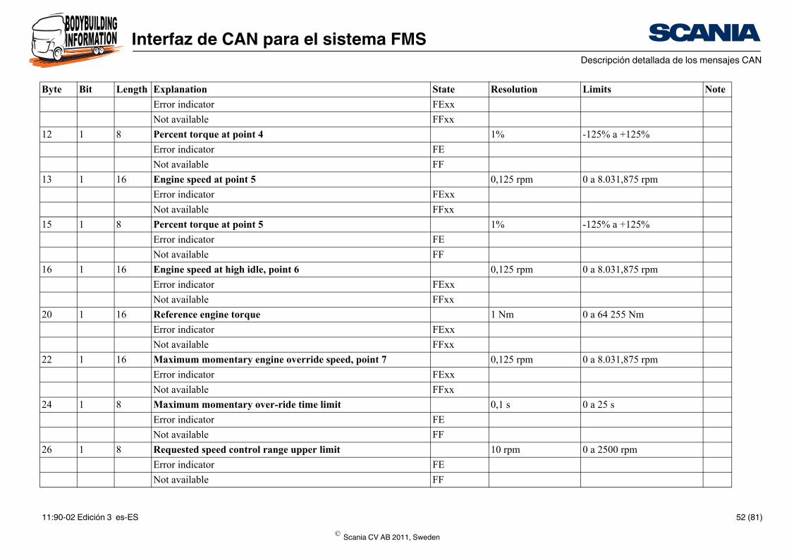
12 1 8 Percent torque at point 4
Error indicator
Not available
13 1 16 Engine speed at point 5
Error indicator
Not available
15 1 8 Percent torque at point 5
Error indicator
Not available
16 1 16 Engine speed at high idle, point 6
Error indicator
Not available
20 1 16 Reference engine torque
Error indicator
Not available
22 1 16 Maximum momentary engine override speed, point 7
Error indicator
Not available
24 1 8 Maximum momentary over-ride time limit
Error indicator
Not available
26 1 8 Requested speed control range upper limit
Error indicator
Not available
Byte Bit Length Explanation
© Scania CV AB 2011, Sweden
11:90-02 Edición 3 es-ES 52 (81)
Interfaz de CAN para el sistema FMSDescripción detallada de los mensajes CAN
1% -125 a +125%
FE
FF
1% -125 a +125%
FE
FF
State Resolution Limits Note
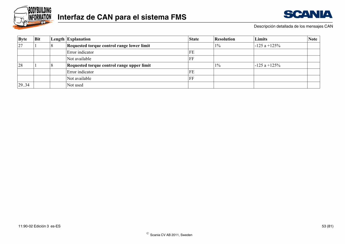
27 1 8 Requested torque control range lower limit
Error indicator
Not available
28 1 8 Requested torque control range upper limit
Error indicator
Not available
29..34 Not used
Byte Bit Length Explanation
© Scania CV AB 2011, Sweden
11:90-02 Edición 3 es-ES 53 (81)
Interfaz de CAN para el sistema FMSDescripción detallada de los mensajes CAN
State Resolution Limits Note
4 0 a 1.000 kPa
FExx
FFxx
0.05 0 a 125 kPa
FE
FF
0.4 0 a 100%
FE
FF
4 kPa 0 a 1.000 kPa
FE
FF
0.0078125 -250 a 251,99 kPa
FExx
FFxx
2 0 a 500 kPa
FExx
FFxx
0.4% 0 a 100% A
FE
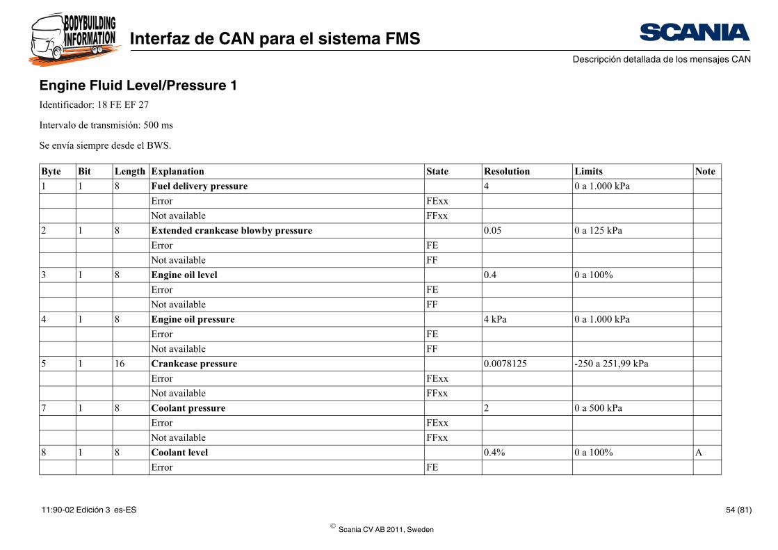
Engine Fluid Level/Pressure 1Identificador: 18 FE EF 27
Intervalo de transmisión: 500 ms
Se envía siempre desde el BWS.
Byte Bit Length Explanation
1 1 8 Fuel delivery pressure
Error
Not available
2 1 8 Extended crankcase blowby pressure
Error
Not available
3 1 8 Engine oil level
Error
Not available
4 1 8 Engine oil pressure
Error
Not available
5 1 16 Crankcase pressure
Error
Not available
7 1 8 Coolant pressure
Error
Not available
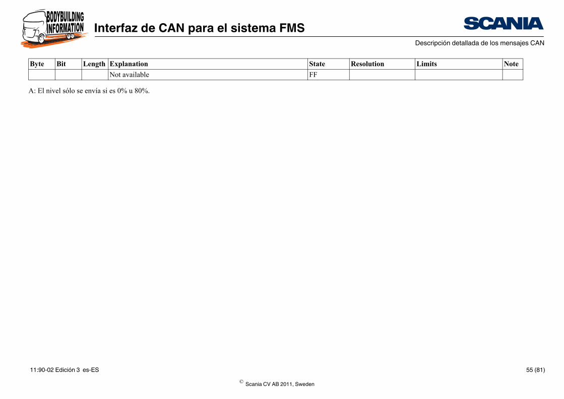
8 1 8 Coolant level
Error
© Scania CV AB 2011, Sweden
11:90-02 Edición 3 es-ES 54 (81)
Interfaz de CAN para el sistema FMSDescripción detallada de los mensajes CAN
FF
State Resolution Limits Note
A: El nivel sólo se envía si es 0% u 80%.
Not available
Byte Bit Length Explanation
© Scania CV AB 2011, Sweden
11:90-02 Edición 3 es-ES 55 (81)
Interfaz de CAN para el sistema FMSDescripción detallada de los mensajes CAN
State Resolution Limits Note
0,05 h/bit 0 a 210 554 060,75 h
FEh
FFh
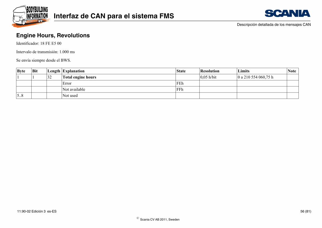
Engine Hours, RevolutionsIdentificador: 18 FE E5 00
Intervalo de transmisión: 1.000 ms
Se envía siempre desde el BWS.
Byte Bit Length Explanation
1 1 32 Total engine hours
Error
Not available
5..8 Not used
© Scania CV AB 2011, Sweden
11:90-02 Edición 3 es-ES 56 (81)
Interfaz de CAN para el sistema FMSDescripción detallada de los mensajes CAN
State Resolution Limits Note
1°C -40 a +210 °C
FE
FF
1°C -40 a +210 °C A
FE
FF
0.03125 -273 a +1,735°C
FExx
FFxx
0.03125 -273 a +1,735°C
FExx
FFxx
1°C -40 a +210 °C
FE
FF
0.4% 0 a 100%
FE
FF
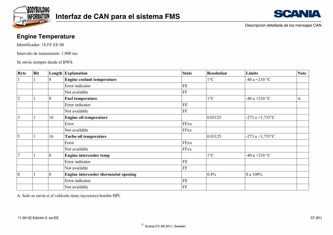
Engine TemperatureIdentificador: 18 FE EE 00
Intervalo de transmisión: 1.000 ms
Se envía siempre desde el BWS.
A: Solo se envía si el vehículo tiene inyectores-bomba HPI.
Byte Bit Length Explanation
1 1 8 Engine coolant temperature
Error indicator
Not available
2 1 8 Fuel temperature
Error indicator
Not available
3 1 16 Engine oil temperature
Error
Not available
5 1 16 Turbo oil temperature
Error
Not available
7 1 8 Engine intercooler temp
Error indicator
Not available
8 1 8 Engine intercooler thermostat opening
Error indicator
Not available
© Scania CV AB 2011, Sweden
11:90-02 Edición 3 es-ES 57 (81)
Interfaz de CAN para el sistema FMSDescripción detallada de los mensajes CAN
State Resolution Limits Note
1 -
-
0x0
0x1
0x2
0x3
0xFE
0xFF
1 -
0-250
0xFE
0xFF
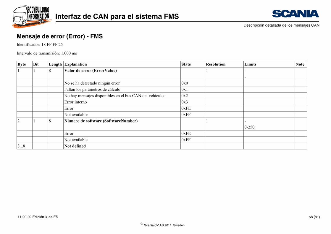
Mensaje de error (Error) - FMSIdentificador: 18 FF FF 25
Intervalo de transmisión: 1.000 ms
Byte Bit Length Explanation
1 1 8 Valor de error (ErrorValue)
No se ha detectado ningún error
Faltan los parámetros de cálculo
No hay mensajes disponibles en el bus CAN del vehículo
Error interno
Error
Not available
2 1 8 Número de software (SoftwareNumber)
Error
Not available
3...8 Not defined
© Scania CV AB 2011, Sweden
11:90-02 Edición 3 es-ES 58 (81)
Interfaz de CAN para el sistema FMSDescripción detallada de los mensajes CAN
State Resolution Limits Note
00
01
10
11
00
01
10
11
ASCII
FExxxxxxh
FFxxxxxxh
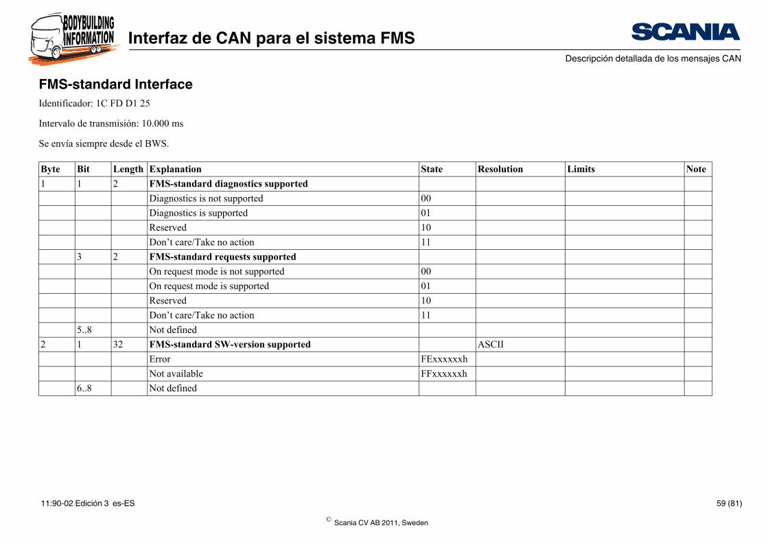
FMS-standard InterfaceIdentificador: 1C FD D1 25
Intervalo de transmisión: 10.000 ms
Se envía siempre desde el BWS.
Byte Bit Length Explanation
1 1 2 FMS-standard diagnostics supported
Diagnostics is not supported
Diagnostics is supported
Reserved
Don’t care/Take no action
3 2 FMS-standard requests supported
On request mode is not supported
On request mode is supported
Reserved
Don’t care/Take no action
5..8 Not defined
2 1 32 FMS-standard SW-version supported
Error
Not available
6..8 Not defined
© Scania CV AB 2011, Sweden
11:90-02 Edición 3 es-ES 59 (81)
Interfaz de CAN para el sistema FMSDescripción detallada de los mensajes CAN
State Resolution Limits Note
0.5 l/bit 0 a 2, 105, 540, 607,5 l
FExxxxxxh
FFxxxxxxh
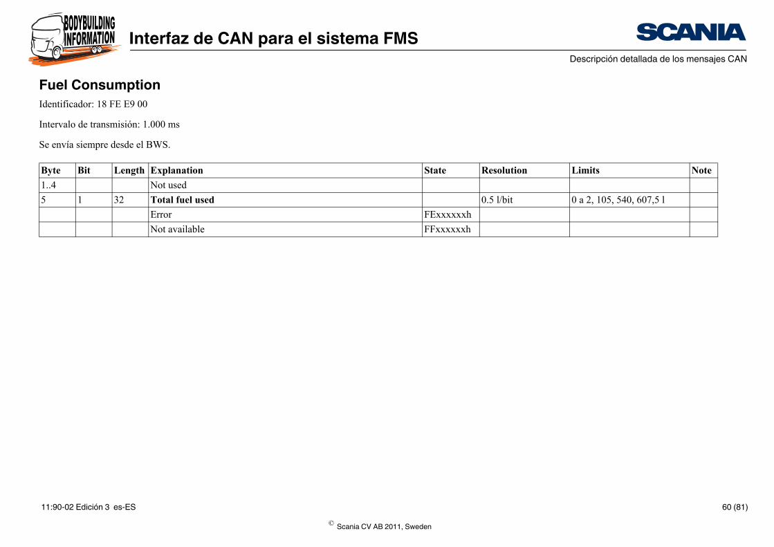
Fuel ConsumptionIdentificador: 18 FE E9 00
Intervalo de transmisión: 1.000 ms
Se envía siempre desde el BWS.
Byte Bit Length Explanation
1..4 Not used
5 1 32 Total fuel used
Error
Not available
© Scania CV AB 2011, Sweden
11:90-02 Edición 3 es-ES 60 (81)
Interfaz de CAN para el sistema FMSDescripción detallada de los mensajes CAN
State Resolution Limits Note
0,05 l/h por bit 0 a 3,212.75 l/h
FExxh
FFxxh
1/512 km/l por bit 0 a 125,5 km/l
FExxh
FFxxh
1/512 km/l por bit 0 a 125,5 km/l
FExxh
FFxxh
0.4% 0 a 100%
FExxh
FFxxh
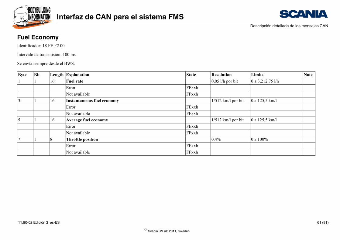
Fuel EconomyIdentificador: 18 FE F2 00
Intervalo de transmisión: 100 ms
Se envía siempre desde el BWS.
Byte Bit Length Explanation
1 1 16 Fuel rate
Error
Not available
3 1 16 Instantaneous fuel economy
Error
Not available
5 1 16 Average fuel economy
Error
Not available
7 1 8 Throttle position
Error
Not available
© Scania CV AB 2011, Sweden
11:90-02 Edición 3 es-ES 61 (81)
Interfaz de CAN para el sistema FMSDescripción detallada de los mensajes CAN
State Resolution Limits Note
1/bit 0h a FFFFFFFFh A
FExxxxxx
FFxxxxxx B
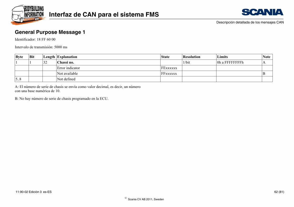
General Purpose Message 1Identificador: 18 FF 60 00
Intervalo de transmisión: 5000 ms
A: El número de serie de chasis se envía como valor decimal, es decir, un número con una base numérica de 10.
B: No hay número de serie de chasis programado en la ECU.
Byte Bit Length Explanation
1 1 32 Chassi no.
Error indicator
Not available
5..8 Not defined
© Scania CV AB 2011, Sweden
11:90-02 Edición 3 es-ES 62 (81)
Interfaz de CAN para el sistema FMSDescripción detallada de los mensajes CAN
State Resolution Limits Note
0.001 0 - 4,211,081.215 A
0xFExxxxxx
0xFFxxxxxx
neTo- 0.001 0 - 4,211,081.215 A
0xFExxxxxx
0xFFxxxxxx
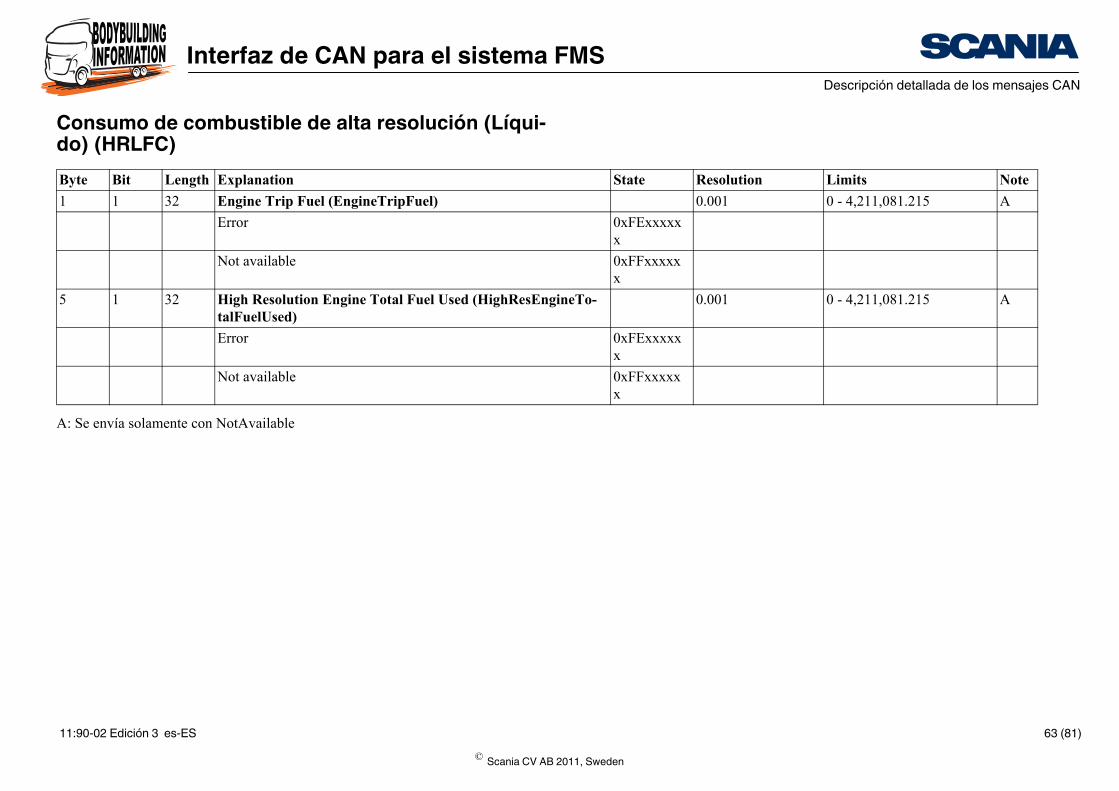
Consumo de combustible de alta resolución (Líqui-do) (HRLFC)
A: Se envía solamente con NotAvailable
Byte Bit Length Explanation
1 1 32 Engine Trip Fuel (EngineTripFuel)
Error
Not available
5 1 32 High Resolution Engine Total Fuel Used (HighResEngitalFuelUsed)
Error
Not available
© Scania CV AB 2011, Sweden
11:90-02 Edición 3 es-ES 63 (81)
Interfaz de CAN para el sistema FMSDescripción detallada de los mensajes CAN
State Resolution Limits Note
5 m/bit 0 a 21 055 406 km
FExxxxxxh
FFxxxxxxh
5 m/bit 0 a 21 055 406 km
FExxxxxxh
FFxxxxxxh
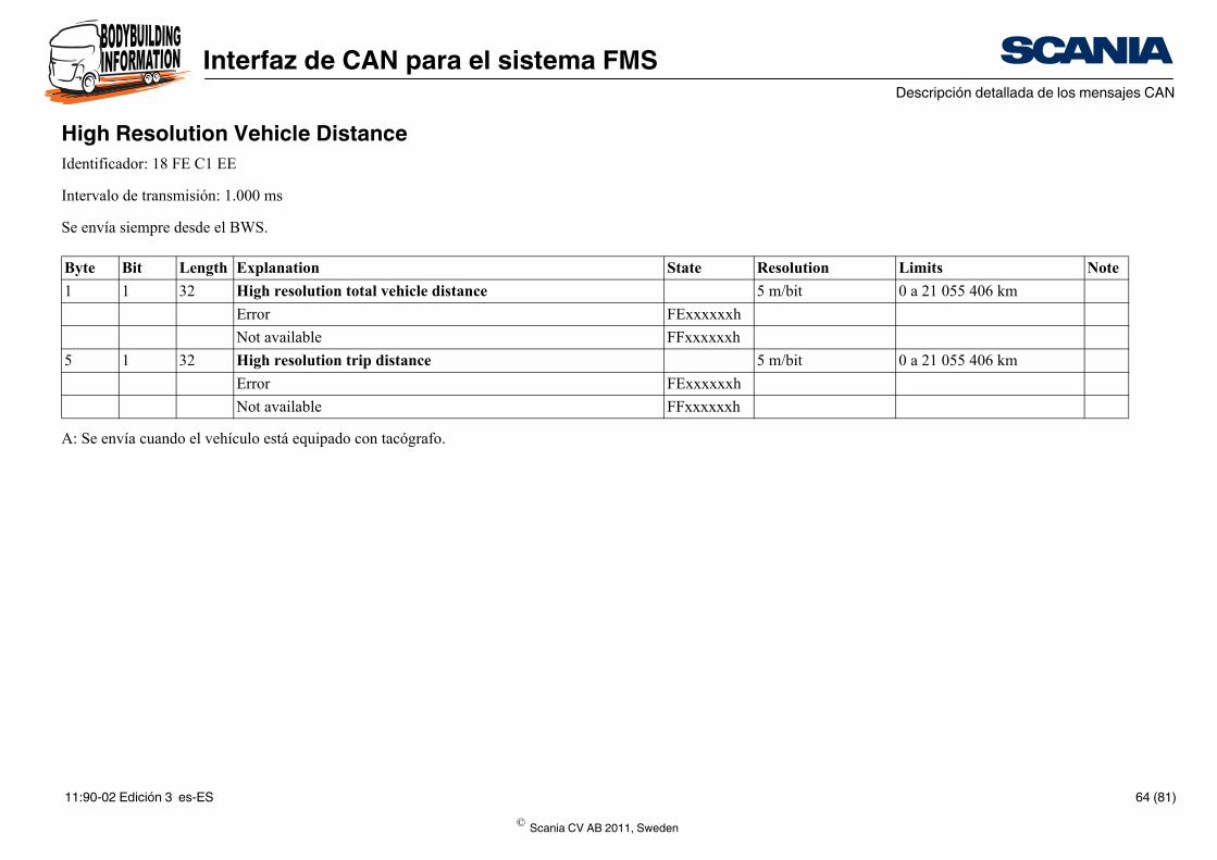
High Resolution Vehicle DistanceIdentificador: 18 FE C1 EE
Intervalo de transmisión: 1.000 ms
Se envía siempre desde el BWS.
A: Se envía cuando el vehículo está equipado con tacógrafo.
Byte Bit Length Explanation
1 1 32 High resolution total vehicle distance
Error
Not available
5 1 32 High resolution trip distance
Error
Not available
© Scania CV AB 2011, Sweden
11:90-02 Edición 3 es-ES 64 (81)
Interfaz de CAN para el sistema FMSDescripción detallada de los mensajes CAN
State Resolution Limits Note
2 kPa 0 a 500 kPa
FE
FF
1°C -40 a +210 °C
FE
FF
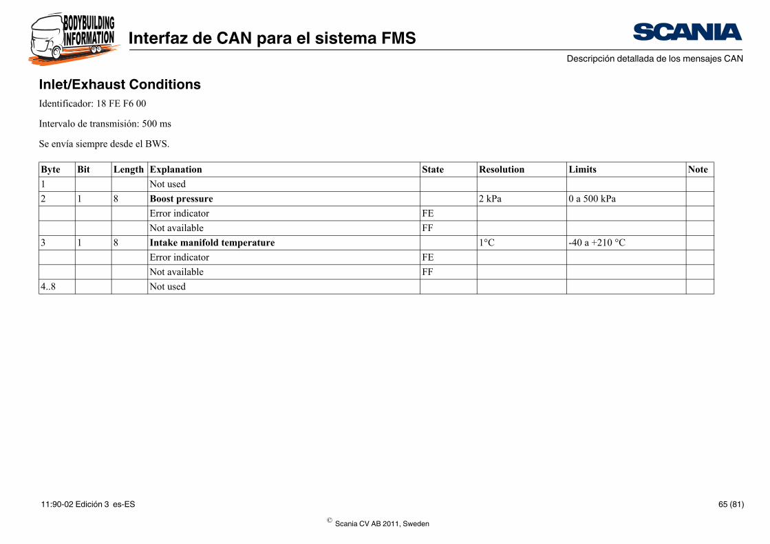
Inlet/Exhaust ConditionsIdentificador: 18 FE F6 00
Intervalo de transmisión: 500 ms
Se envía siempre desde el BWS.
Byte Bit Length Explanation
1 Not used
2 1 8 Boost pressure
Error indicator
Not available
3 1 8 Intake manifold temperature
Error indicator
Not available
4..8 Not used
© Scania CV AB 2011, Sweden
11:90-02 Edición 3 es-ES 65 (81)
Interfaz de CAN para el sistema FMSDescripción detallada de los mensajes CAN
State Resolution Limits Note
1 0-3
0x0
0x1
0x2
0x3
1
0x0
0x1
0x2
0x3
1
0x0
0x1
0x2
0x3
1
0x0
0x1
0x2
0x3
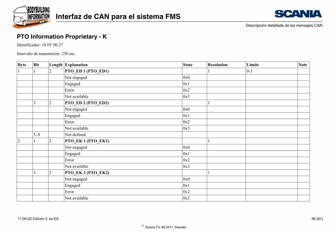
PTO Information Proprietary - KIdentificador: 18 FF 90 27
Intervalo de transmisión: 250 ms
Byte Bit Length Explanation
1 1 2 PTO_ED 1 (PTO_ED1)
Not engaged
Engaged
Error
Not available
3 2 PTO_ED 2 (PTO_ED2)
Not engaged
Engaged
Error
Not available
5..8 Not defined
2 1 2 PTO_EK 1 (PTO_EK1)
Not engaged
Engaged
Error
Not available
3 2 PTO_EK 2 (PTO_EK2)
Not engaged
Engaged
Error
Not available
© Scania CV AB 2011, Sweden
11:90-02 Edición 3 es-ES 66 (81)
Interfaz de CAN para el sistema FMSDescripción detallada de los mensajes CAN
1
0x0
0x1
0x2
0x3
0x0
0x1
0x2
0x3
1
0x0
0x1
0x2
0x3
1
0x0
0x1
0x2
0x3
1 A
0x0
State Resolution Limits Note
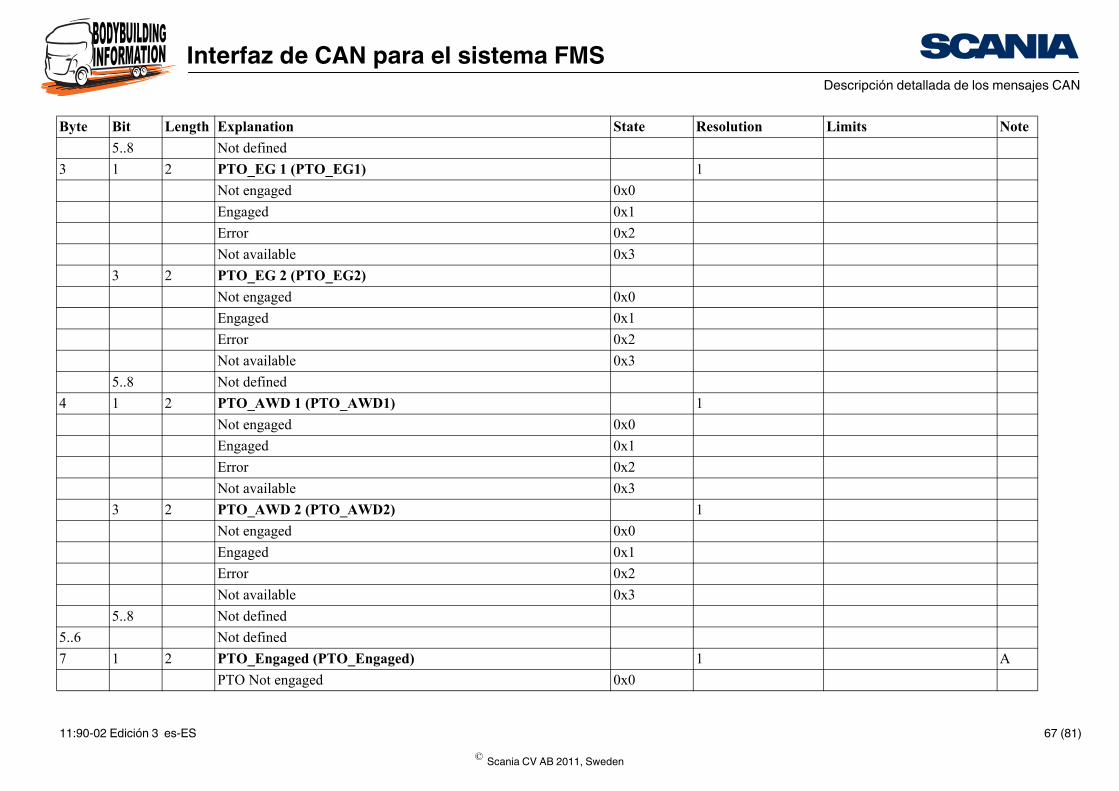
5..8 Not defined
3 1 2 PTO_EG 1 (PTO_EG1)
Not engaged
Engaged
Error
Not available
3 2 PTO_EG 2 (PTO_EG2)
Not engaged
Engaged
Error
Not available
5..8 Not defined
4 1 2 PTO_AWD 1 (PTO_AWD1)
Not engaged
Engaged
Error
Not available
3 2 PTO_AWD 2 (PTO_AWD2)
Not engaged
Engaged
Error
Not available
5..8 Not defined
5..6 Not defined
7 1 2 PTO_Engaged (PTO_Engaged)
PTO Not engaged
Byte Bit Length Explanation
© Scania CV AB 2011, Sweden
11:90-02 Edición 3 es-ES 67 (81)
Interfaz de CAN para el sistema FMSDescripción detallada de los mensajes CAN
0x1
0x2
0x3
1
0x0
0x1
0x2
0x3
State Resolution Limits Note
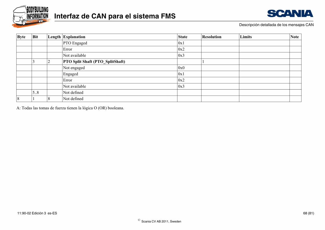
A: Todas las tomas de fuerza tienen la lógica O (OR) booleana.
PTO Engaged
Error
Not available
3 2 PTO Split Shaft (PTO_SplitShaft)
Not engaged
Engaged
Error
Not available
5..8 Not defined
8 1 8 Not defined
Byte Bit Length Explanation
© Scania CV AB 2011, Sweden
11:90-02 Edición 3 es-ES 68 (81)
Interfaz de CAN para el sistema FMSDescripción detallada de los mensajes CAN
State Resolution Limits Note
5 - 160.635 - 160,640 km(off-set - 160.635)
0xFE
0xFF
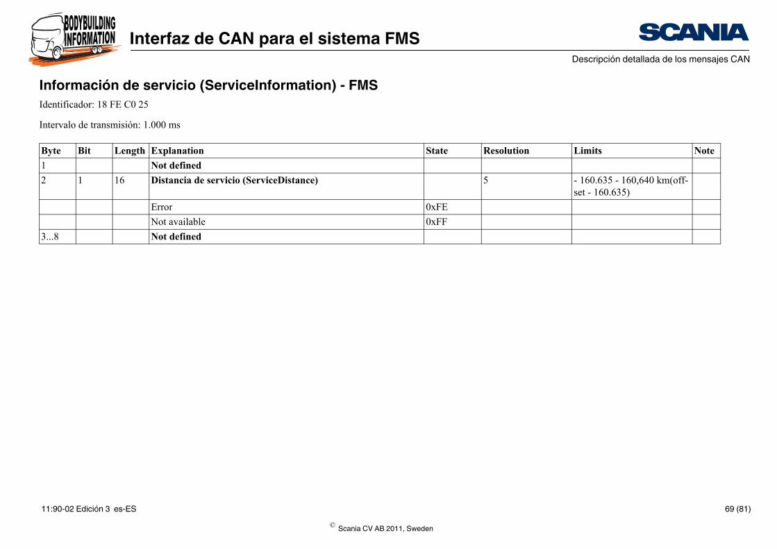
Información de servicio (ServiceInformation) - FMSIdentificador: 18 FE C0 25
Intervalo de transmisión: 1.000 ms
Byte Bit Length Explanation
1 Not defined
2 1 16 Distancia de servicio (ServiceDistance)
Error
Not available
3...8 Not defined
© Scania CV AB 2011, Sweden
11:90-02 Edición 3 es-ES 69 (81)
Interfaz de CAN para el sistema FMSDescripción detallada de los mensajes CAN
State Resolution Limits Note
000
001
010
011
100
110
111
000
001
010
011
100
110
111
00
01
10
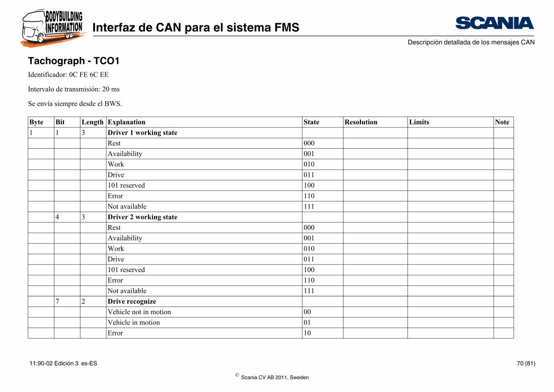
Tachograph - TCO1Identificador: 0C FE 6C EE
Intervalo de transmisión: 20 ms
Se envía siempre desde el BWS.
Byte Bit Length Explanation
1 1 3 Driver 1 working state
Rest
Availability
Work
Drive
101 reserved
Error
Not available
4 3 Driver 2 working state
Rest
Availability
Work
Drive
101 reserved
Error
Not available
7 2 Drive recognize
Vehicle not in motion
Vehicle in motion
Error
© Scania CV AB 2011, Sweden
11:90-02 Edición 3 es-ES 70 (81)
Interfaz de CAN para el sistema FMSDescripción detallada de los mensajes CAN
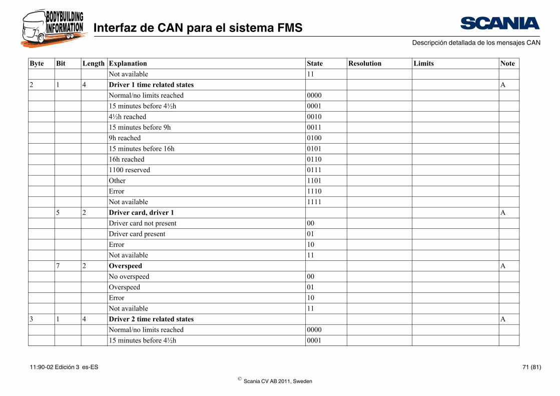
11
A
0000
0001
0010
0011
0100
0101
0110
0111
1101
1110
1111
A
00
01
10
11
A
00
01
10
11
A
0000
0001
State Resolution Limits Note
Not available
2 1 4 Driver 1 time related states
Normal/no limits reached
15 minutes before 4½h
4½h reached
15 minutes before 9h
9h reached
15 minutes before 16h
16h reached
1100 reserved
Other
Error
Not available
5 2 Driver card, driver 1
Driver card not present
Driver card present
Error
Not available
7 2 Overspeed
No overspeed
Overspeed
Error
Not available
3 1 4 Driver 2 time related states
Normal/no limits reached
15 minutes before 4½h
Byte Bit Length Explanation
© Scania CV AB 2011, Sweden
11:90-02 Edición 3 es-ES 71 (81)
Interfaz de CAN para el sistema FMSDescripción detallada de los mensajes CAN
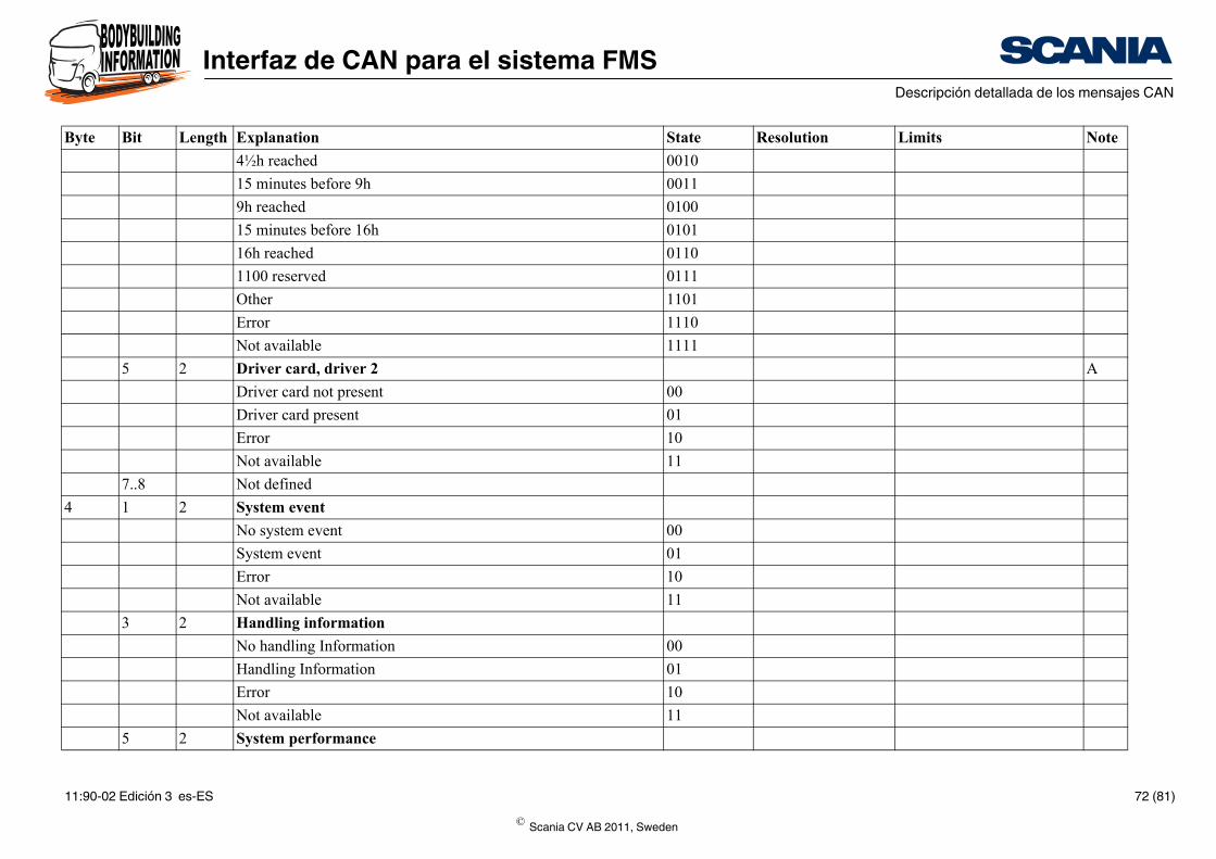
0010
0011
0100
0101
0110
0111
1101
1110
1111
A
00
01
10
11
00
01
10
11
00
01
10
11
State Resolution Limits Note
4½h reached
15 minutes before 9h
9h reached
15 minutes before 16h
16h reached
1100 reserved
Other
Error
Not available
5 2 Driver card, driver 2
Driver card not present
Driver card present
Error
Not available
7..8 Not defined
4 1 2 System event
No system event
System event
Error
Not available
3 2 Handling information
No handling Information
Handling Information
Error
Not available
5 2 System performance
Byte Bit Length Explanation
© Scania CV AB 2011, Sweden
11:90-02 Edición 3 es-ES 72 (81)
Interfaz de CAN para el sistema FMSDescripción detallada de los mensajes CAN
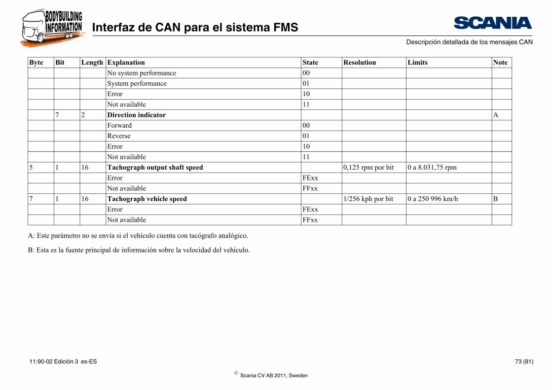
00
01
10
11
A
00
01
10
11
0,125 rpm por bit 0 a 8.031,75 rpm
FExx
FFxx
1/256 kph por bit 0 a 250 996 km/h B
FExx
FFxx
State Resolution Limits Note
A: Este parámetro no se envía si el vehículo cuenta con tacógrafo analógico.
B: Esta es la fuente principal de información sobre la velocidad del vehículo.
No system performance
System performance
Error
Not available
7 2 Direction indicator
Forward
Reverse
Error
Not available
5 1 16 Tachograph output shaft speed
Error
Not available
7 1 16 Tachograph vehicle speed
Error
Not available
Byte Bit Length Explanation
© Scania CV AB 2011, Sweden
11:90-02 Edición 3 es-ES 73 (81)
Interfaz de CAN para el sistema FMSDescripción detallada de los mensajes CAN
State Resolution Limits Note
0,25 s/bit 0 a 62,5 s
FEh
FFh
1 min/bit 0 a 250 min
FEh
FFh
1 h/bit 0 a 250 h
FEh
FFh
1 mes/bit 0 a 250 meses
FEh
FFh
0,25 día/bit 0 a 62,5 días
FEh
FFh
1 Año/bit 1985 a 2235 Offset + 1985 años
FEh
FFh
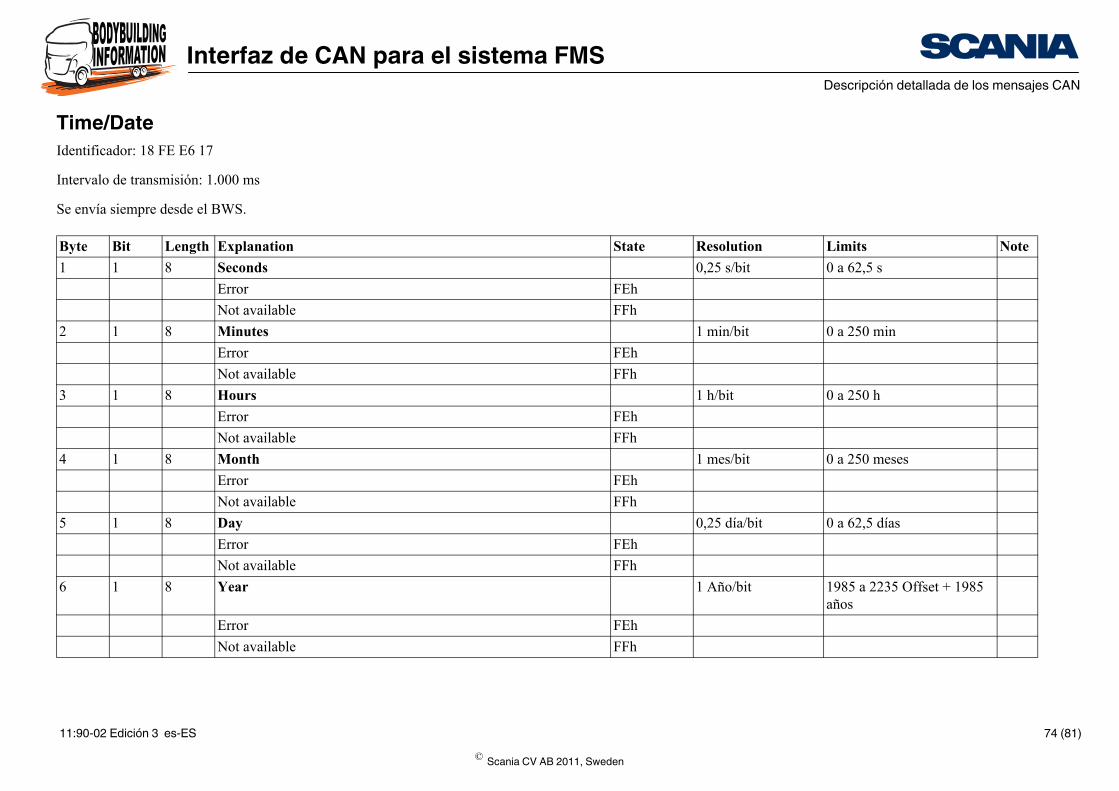
Time/DateIdentificador: 18 FE E6 17
Intervalo de transmisión: 1.000 ms
Se envía siempre desde el BWS.
Byte Bit Length Explanation
1 1 8 Seconds
Error
Not available
2 1 8 Minutes
Error
Not available
3 1 8 Hours
Error
Not available
4 1 8 Month
Error
Not available
5 1 8 Day
Error
Not available
6 1 8 Year
Error
Not available
© Scania CV AB 2011, Sweden
11:90-02 Edición 3 es-ES 74 (81)
Interfaz de CAN para el sistema FMSDescripción detallada de los mensajes CAN
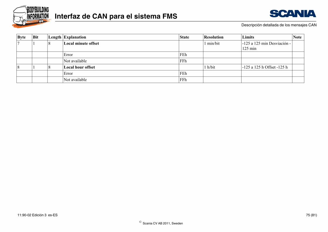
1 min/bit -125 a 125 min Desviación -125 min
FEh
FFh
1 h/bit -125 a 125 h Offset -125 h
FEh
FFh
State Resolution Limits Note
7 1 8 Local minute offset
Error
Not available
8 1 8 Local hour offset
Error
Not available
Byte Bit Length Explanation
© Scania CV AB 2011, Sweden
11:90-02 Edición 3 es-ES 75 (81)
Interfaz de CAN para el sistema FMSDescripción detallada de los mensajes CAN
State Resolution Limits Note
1 ASCII, length m bytes
1 ASCII, start at byte m
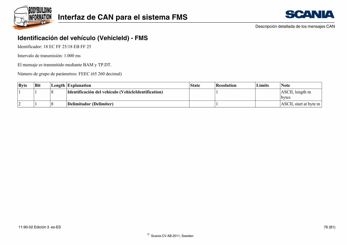
Identificación del vehículo (VehicleId) - FMSIdentificador: 18 EC FF 25/18 EB FF 25
Intervalo de transmisión: 1.000 ms
El mensaje es transmitido mediante BAM y TP.DT.
Número de grupo de parámetros: FEEC (65 260 decimal)
Byte Bit Length Explanation
1 1 8 Identificación del vehículo (VehicleIdentification)
2 1 8 Delimitador (Delimiter)
© Scania CV AB 2011, Sweden
11:90-02 Edición 3 es-ES 76 (81)
Interfaz de CAN para el sistema FMSDescripción detallada de los mensajes CAN
State Resolution Limits Note
En mapa de bits
FE
FF
0.5 kg/bit 0 a 32 127,5 kg
FExx
FFxx
2 kg/bit 0 a 128 510 kg
FExx
FFxx
2 kg/bit 0 a 128 510 kg
FExx
FFxx
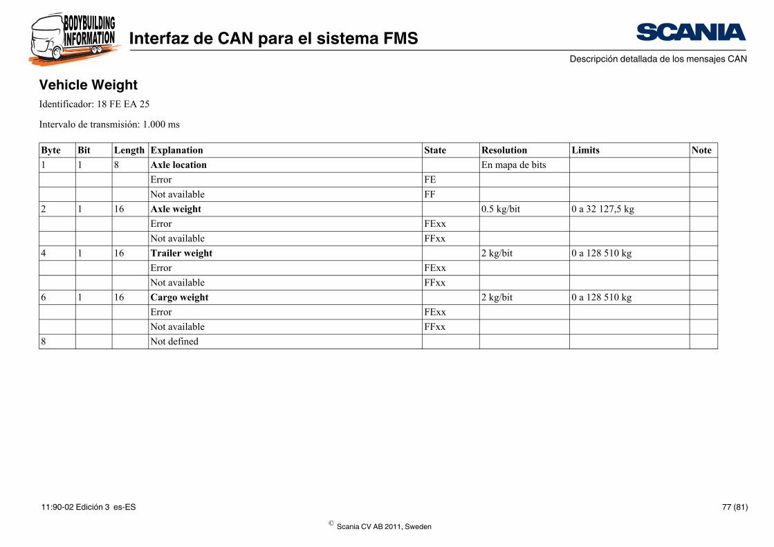
Vehicle WeightIdentificador: 18 FE EA 25
Intervalo de transmisión: 1.000 ms
Byte Bit Length Explanation
1 1 8 Axle location
Error
Not available
2 1 16 Axle weight
Error
Not available
4 1 16 Trailer weight
Error
Not available
6 1 16 Cargo weight
Error
Not available
8 Not defined
© Scania CV AB 2011, Sweden
11:90-02 Edición 3 es-ES 77 (81)
Interfaz de CAN para el sistema FMSDescripción detallada de los mensajes CAN
State Resolution Limits Note
0.4 0 - 100% A
FE
FF
0.4 0 - 100% A
FE
FF
0.4 0 - 100% B
FE
FF
0.4 0 - 100% B
FE
FF
0.4 0 - 100% C
FE
FF
0.4 0 - 100% C
FE
FF
0.4 0 - 100% D
FE
FF
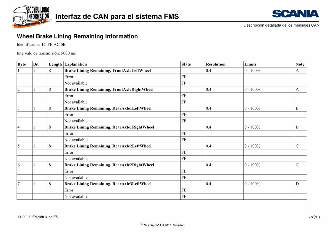
Wheel Brake Lining Remaining InformationIdentificador: 1C FE AC 0B
Intervalo de transmisión: 5000 ms
Byte Bit Length Explanation
1 1 8 Brake Lining Remaining, FrontAxleLeftWheel
Error
Not available
2 1 8 Brake Lining Remaining, FrontAxleRightWheel
Error
Not available
3 1 8 Brake Lining Remaining, RearAxle1LeftWheel
Error
Not available
4 1 8 Brake Lining Remaining, RearAxle1RightWheel
Error
Not available
5 1 8 Brake Lining Remaining, RearAxle2LeftWheel
Error
Not available
6 1 8 Brake Lining Remaining, RearAxle2RightWheel
Error
Not available
7 1 8 Brake Lining Remaining, RearAxle3LeftWheel
Error
Not available
© Scania CV AB 2011, Sweden
11:90-02 Edición 3 es-ES 78 (81)
Interfaz de CAN para el sistema FMSDescripción detallada de los mensajes CAN
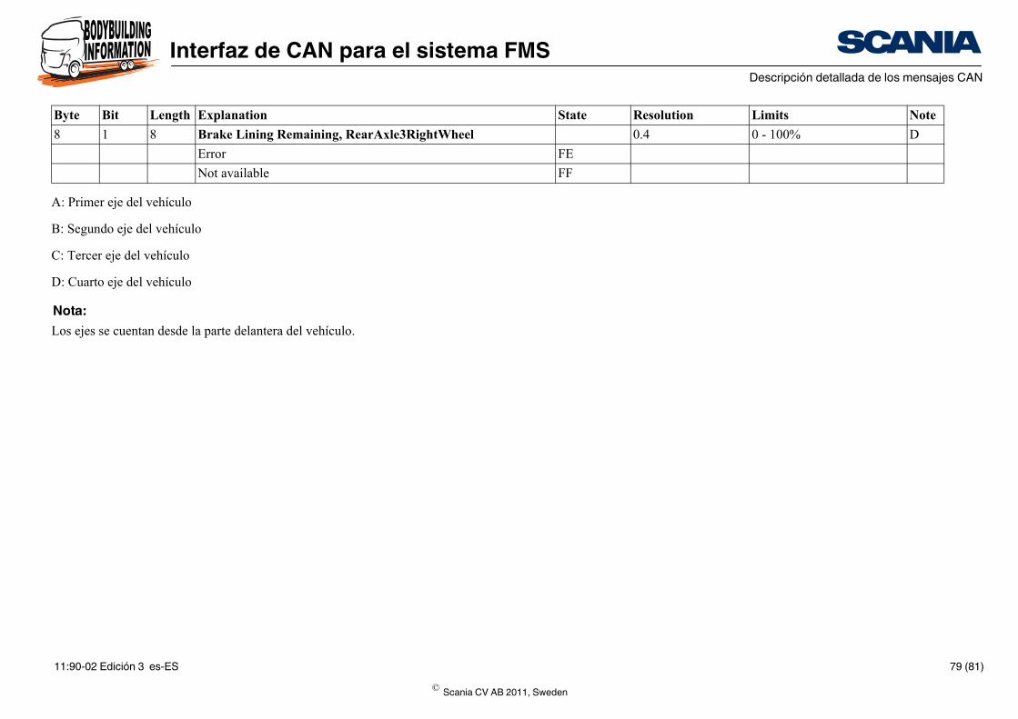
0.4 0 - 100% D
FE
FF
State Resolution Limits Note
A: Primer eje del vehículo
B: Segundo eje del vehículo
C: Tercer eje del vehículo
D: Cuarto eje del vehículo
Nota:Los ejes se cuentan desde la parte delantera del vehículo.
8 1 8 Brake Lining Remaining, RearAxle3RightWheel
Error
Not available
Byte Bit Length Explanation
© Scania CV AB 2011, Sweden
11:90-02 Edición 3 es-ES 79 (81)
Interfaz de CAN para el sistema FMSDirecciones de origen
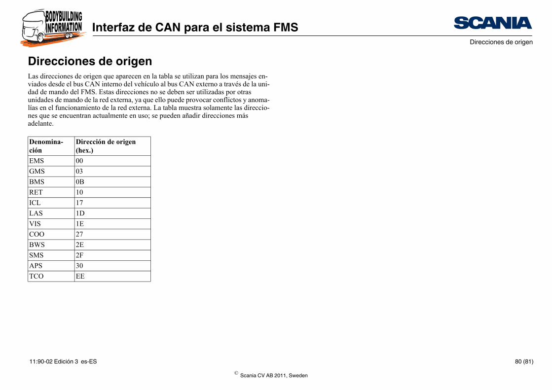
Direcciones de origenLas direcciones de origen que aparecen en la tabla se utilizan para los mensajes en-viados desde el bus CAN interno del vehículo al bus CAN externo a través de la uni-dad de mando del FMS. Estas direcciones no se deben ser utilizadas por otras unidades de mando de la red externa, ya que ello puede provocar conflictos y anoma-lías en el funcionamiento de la red externa. La tabla muestra solamente las direccio-nes que se encuentran actualmente en uso; se pueden añadir direcciones más adelante.
Denomina-ción
Dirección de origen (hex.)
EMS 00
GMS 03
BMS 0B
RET 10
ICL 17
LAS 1D
VIS 1E
COO 27
BWS 2E
SMS 2F
APS 30
TCO EE
© Scania CV AB 2011, Sweden
11:90-02 Edición 3 es-ES 80 (81)
Interfaz de CAN para el sistema FMSNúmeros del grupo de parámetros
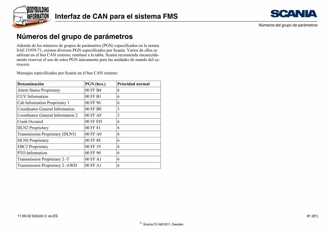
Números del grupo de parámetrosAdemás de los números de grupos de parámetros (PGN) especificados en la norma SAE J1939-71, existen diversos PGN especificados por Scania. Varios de ellos se utilizan en el bus CAN externo; remítase a la tabla. Scania recomienda encarecida-mente reservar el uso de estos PGN únicamente para las unidades de mando del ca-rrocero.
Mensajes especificados por Scania en el bus CAN externo:
Denominación PGN (hex.) Prioridad normal
Alarm Status Proprietary 00 FF B4 6
CUV Information 00 FF B1 6
Cab Information Proprietary 1 00 FF 96 6
Coordinator General Information 00 FF B0 3
Coordinator General Information 2 00 FF AF 3
Crash Occured 00 FF FD 6
DLN2 Proprietary 00 FF 81 6
Transmission Proprietary (DLN5) 00 FF A0 6
DLN8 Proprietary 00 FF 88 6
EBC2 Proprietary 00 FF 19 6
PTO Information 00 FF 90 6
Transmission Proprietary 2 -T 00 FF A1 6
Transmission Proprietary 2 -AWD 00 FF A1 6
© Scania CV AB 2011, Sweden
11:90-02 Edición 3 es-ES 81 (81)