GEOLOGIA DEL CAMPO GEOTERMICO DE CERRO … · GEOLOGIA DEL CAMPO GEOTERMICO DE CERRO PRIETO . I....
24
GEOLOGIA DEL CAMPO GEOTERMICO DE CERRO PRIETO I. Puente C. y A. de la Pena L. Comisi6n Federal de Electricidad Coordinadora Ejecutiva de Cerro Prieto Mexicali, Baja California, Mexico I. lliTRODUCCION El Gobierno Mexicano consciente de las dades futuras, dotar de fluido electrico a versas zonas de RepUblica Mexicana y realista - de que los yaci!Jrl.entos de energeticos no renova- - bles, seran agotados al futuro, ha dado actualrnen- te fuerte :impulso a la investigacion, con el fin - de aprovechar los renovables y en este caso la explotacion del vapor end6geno COIro fluido para la generaci6n de energfa electrica tan escasa en la porci6n noroeste de nuestro pafs, donde la - naturaleza diffcilrnente nos impide la construccion de hidroelectricas, pero afortunadamente nos ha -- proporcionado dos energaicos renovables, COIro 10- son el vapor que se extrae de las profun- didades de la y en un futuro no la- posible instalacion de plantas electricas en base- a la captacian de los rayos solares. La. Comision Federal de Electricidad, en sentacion del Gobierno r,1exicano, dispuso hacer- partfcipe cenuestras a otros rniembros de la Comunidad Inter- nacional. En base a 10 anterior, se celebro un -- convenio en el afio de 1977, con el Departamento de Energfa de los Estados Unidos de con el fin de experiencias en areas de inves tigaci6n que comprenden: geologfa, geoHsica, goo qufrnica, roovimientos corticales I e ingenierfa de ::- yacimientos, con el fin de conocer y explotar razo nablemente el vapor end6geno del Campo Geot&rnico=- de Cerro Prieto. II. - GEQ:W:;IA GENERAL El campo actual de explotaci6n, esta ubicado- en la planicie aluvial del Valle de cons tituida en partes par sedimentos cuaternarios de ::- pie de monte de ;La Sierra de los Cucapah y neltai- cos depositados por las corrientes divagantes del- Rio Colorado, siendo la i1nica praninencia dentro - del Valle, el volcan riodacftico de Cerro Prieto - que data de haoe menos de 700,000 aiios. los dep6- sitos cuaternarios estan sobreyaciendo a sedimen-- tos Cenozoicos metaforrnizados, los que a su vez so breyaoen discordantanente sobre el basamento gran! tico y metasedimentario del Cretacico Superior - (Figs. 1 Y 2). III . - TEX.:'IDNlCA El Campo GeoMrrnico de Cerro Prieto, se liza dentro del patron tect6nico denominado San An del cual se derivan diferentes ramales, sien do al que hetros denaninado Cerro Prieto (posible::- prolongacion de la falla de San Jacinto), donne se localiza la zona geotennica de Cerro Prieto. nos autores, Ie han denominado a este patron de llas del tipo transfonne, de las que se derivan centros de dispersion, siendo la evidencia de - estos centros, la actividad volcanica reciente 1 jambres de taUblores, depresiones ooeanicas y vidad geoterrnica 3 y 4). Debido a las estructuras geol6gicas almacenan los de agua caliente y el mento en el Valle de estan cubiertas sedimentos deltaicos no consolidados y ",,::'''U.'.).JLL::>'-'LL dados ha side necesaria la aplicaci6n de diferen-- tes geoHsicos, con el fin de conocer el - camportamiento y posici6n, tanto de los sedimentos consolidados, COIro del basamento granftico y meta- sedimentario • los estudios geoffsicos 'han proporcionado in fonraci6n Msicamente del cornportamiento estructu=- ral del basamento: de los sedimentos Cenozoicos -- que 10 ha side escasa, com- portar estructuralmente en fonna pero mas compleja por su cornposici6n (Figs. 5, 6 y 7) • El sistema principal de fallas que hemos de- naminado Cerro Prieto, tiene rumJ::;o NW-SE ,- con echados indistintarrente al Wy E, Y para le- 10 a los afallamientos COIro Imperial, Cuca pah, Salada, Algodones, San Andreas, ElsinG ra, Nission Creek y San Jacinto (Fig. 3)-=- Casi nonrales al sistema Cerro Prieto, se -- presentan fallas que hernos denominado Sistema Se-- cundario Volcano, con rumJ::;o predcminante sfll)'-NE -- con echados al NW y al SE. Estos sistemas defa-- llas combinados, han fonnado aparentemente una to- pograffa escalonada con prorninencias (Horst) y fo- sas (Grabens). En base a 10 anterior, se ha conceptuado un- rrodelo geol6qico, el cual se ha definido COIro una- piramide escalonada y alargada de a SE y reoor- tada en sus lados W y E (Figs. 8 y 9). IV. - DESCRIPCION GENERAL DE lAS UNIDADFS LrroI.OOI- CAS A, BY C. UNIDAD LI'IOI.OOICA A.- Conpuesta per sedimen,.. tos continentales no consolidados y semiconsolida"" a los que se les han asignado una edad Cuater no diferenciada, integrada por arcillas, li-;:" roos, arenas y gravas en fonna repetitiva, dose encontrado en ellos, annazones de gaster6po.,..- dos de agua dulce {Pozo M-5 a 500 y 800m de 17
Transcript of GEOLOGIA DEL CAMPO GEOTERMICO DE CERRO … · GEOLOGIA DEL CAMPO GEOTERMICO DE CERRO PRIETO . I....
GEOLOGIA DEL CAMPO GEOTERMICO DE CERRO PRIETO I. Puente C. y A. de la Pena L.
Comisi6n Federal de Electricidad Coordinadora Ejecutiva de Cerro Prieto
Mexicali, Baja California, Mexico
I. lliTRODUCCION
El Gobierno Mexicano consciente de las dades futuras, dotar de fluido electrico a versas zonas de RepUblica Mexicana y realista de que los yaci!Jrl.entos de energeticos no renova- bles, seran agotados al futuro, ha dado actualrnente fuerte :impulso a la investigacion, con el fin de aprovechar los energ~ticos renovables y en este caso la explotacion del vapor end6geno COIro fluido para la generaci6n de energfa electrica tan escasa en la porci6n noroeste de nuestro pafs, donde la naturaleza diffcilrnente nos impide la construccion de hidroelectricas, pero afortunadamente nos ha - proporcionado dos energaicos renovables, COIro 10son el vapor que se extrae de las profundidades de la y en un futuro no laposible instalacion de plantas electricas en basea la captacian de los rayos solares.
La. Comision Federal de Electricidad, en repr~ sentacion del Gobierno r,1exicano, dispuso hacerpartfcipe cenuestras investigaciones-geot~nnicas,a otros rniembros de la Comunidad Geot~rrnica Internacional. En base a 10 anterior, se celebro un - convenio en el afio de 1977, con el Departamento de Energfa de los Estados Unidos de Nort~ica, con el fin de experiencias en areas de inves tigaci6n que comprenden: geologfa, geoHsica, goo qufrnica, roovimientos corticales I e ingenierfa de ::yacimientos, con el fin de conocer y explotar razo nablemente el vapor end6geno del Campo Geot&rnico=de Cerro Prieto.
II. - GEQ:W:;IA GENERAL
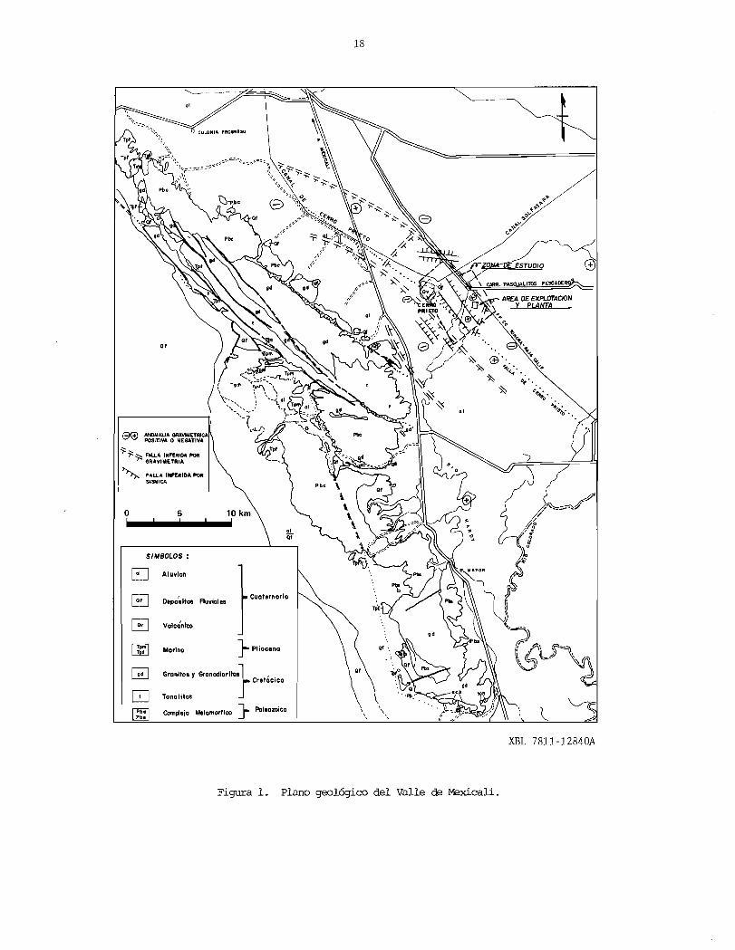
El campo actual de explotaci6n, esta ubicadoen la planicie aluvial del Valle de r~icali, cons tituida en partes par sedimentos cuaternarios de ::pie de monte de ;La Sierra de los Cucapah y neltai cos depositados por las corrientes divagantes delRio Colorado, siendo la i1nica praninencia dentro del Valle, el volcan riodacftico de Cerro Prieto que data de haoe menos de 700,000 aiios. los dep6sitos cuaternarios estan sobreyaciendo a sedimen-tos Cenozoicos metaforrnizados, los que a su vez so breyaoen discordantanente sobre el basamento gran! tico y metasedimentario del Cretacico Superior (Figs. 1 Y 2).
III . - TEX.:'IDNlCA
El Campo GeoMrrnico de Cerro Prieto, se loc~ liza dentro del patron tect6nico denominado San An ~s, del cual se derivan diferentes ramales, sien do al que hetros denaninado Cerro Prieto (posible::
prolongacion de la falla de San Jacinto), donne se localiza la zona geotennica de Cerro Prieto. nos autores, Ie han denominado a este patron de llas del tipo transfonne, de las que se derivan centros de dispersion, siendo la evidencia de estos centros, la actividad volcanica reciente 1
jambres de taUblores, depresiones ooeanicas y vidad geoterrnica 3 y 4).
Debido a las estructuras geol6gicas almacenan los de agua caliente y el mento en el Valle de r~icali estan cubiertas sedimentos deltaicos no consolidados y ",,::'''U.'.).JLL::>'-'LL
dados ha side necesaria la aplicaci6n de diferen-tes m~todos geoHsicos, con el fin de conocer el camportamiento y posici6n, tanto de los sedimentos consolidados, COIro del basamento granftico y metasedimentario •
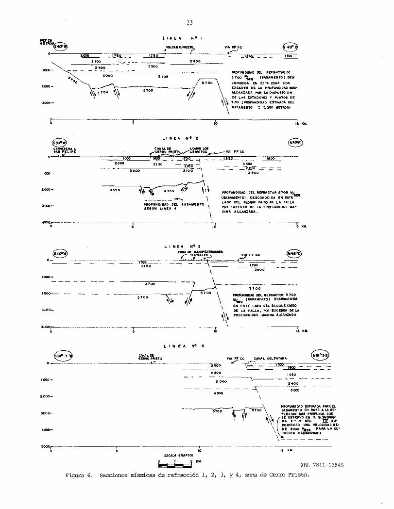
los estudios geoffsicos 'han proporcionado in fonraci6n Msicamente del cornportamiento estructu=ral del basamento: de los sedimentos Cenozoicos - que 10 ha side escasa, debi~dose comportar estructuralmente ~stos en fonna pero mas compleja por su cornposici6n (Figs. 5, 6 y 7) •
El sistema principal de fallas que hemos denaminado Cerro Prieto, tiene rumJ::;o NW-SE, con echados indistintarrente al Wy E, Y parale10 a los afallamientos COIro Imperial, Cuca pah, Salada, Algodones, San Andreas, ElsinG ra, Nission Creek y San Jacinto (Fig. 3)-=-
Casi nonrales al sistema Cerro Prieto, se - presentan fallas que hernos denominado Sistema Se-cundario Volcano, con rumJ::;o predcminante sfll)'-NE -con echados al NW y al SE. Estos sistemas defa-llas combinados, han fonnado aparentemente una topograffa escalonada con prorninencias (Horst) y fosas (Grabens).
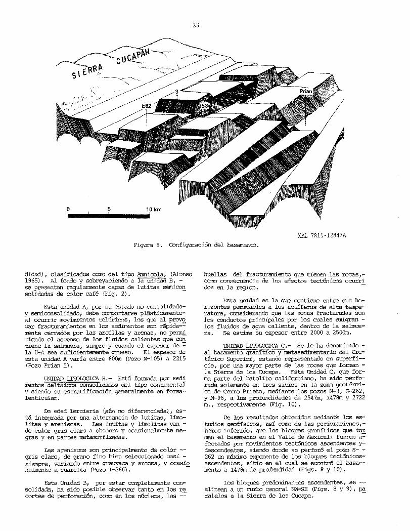
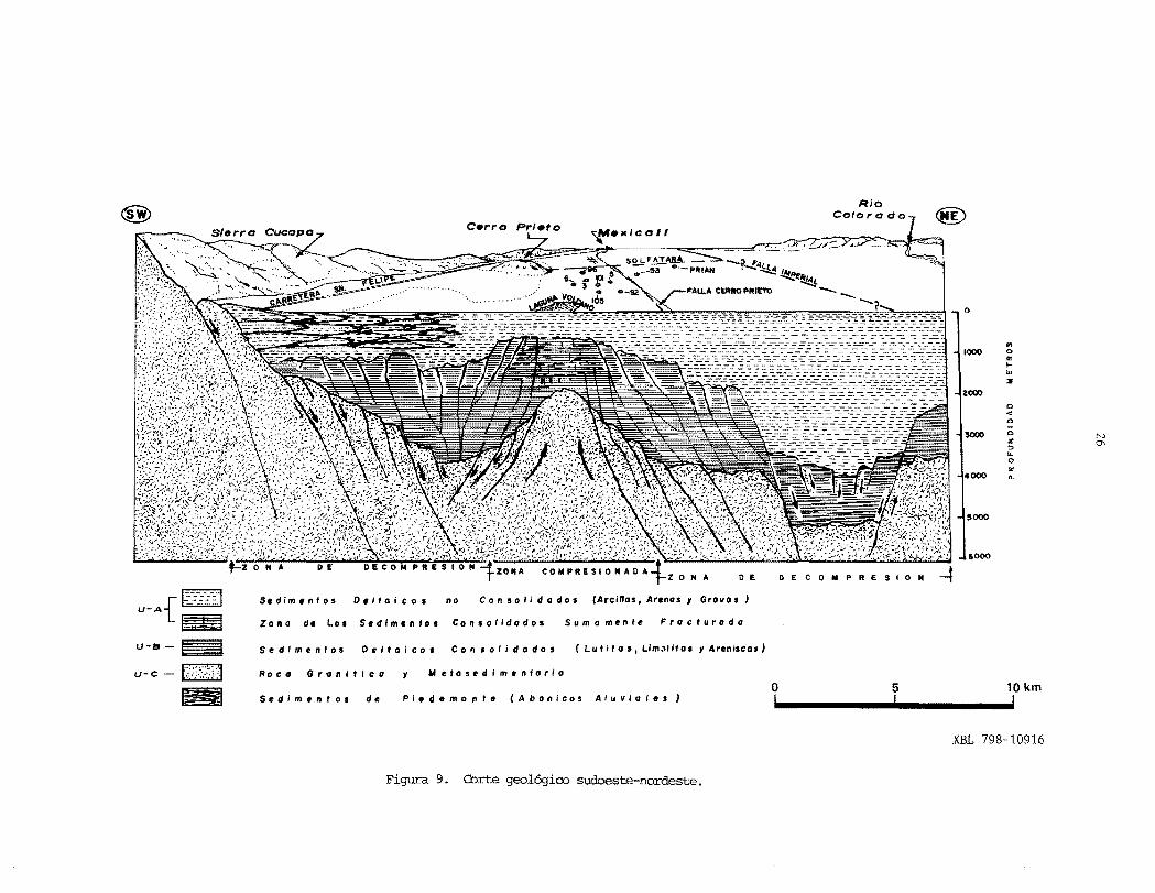
En base a 10 anterior, se ha conceptuado unrrodelo geol6qico, el cual se ha definido COIro unapiramide escalonada y alargada de ~v a SE y reoortada en sus lados W y E (Figs. 8 y 9).
IV. - DESCRIPCION GENERAL DE lAS UNIDADFS LrroI.OOICAS A, BY C.
UNIDAD LI'IOI.OOICA A.- Conpuesta per sedimen,.. tos continentales no consolidados y semiconsolida""
a los que se les han asignado una edad Cuater no diferenciada, integrada por arcillas, li-;:"
roos, arenas y gravas en fonna repetitiva, habi~dose encontrado en ellos, annazones de gaster6po.,..dos de agua dulce {Pozo M-5 a 500 y 800m de prof~,
17
18
----~
--~ r.."OJJK15E ESTUOIO 8)
LITOS PESCAIE
AREA OE EXPLOTACION Y PLANTA
or
~ ):.:. ~ FAlLA INF'ERIDA POR GRAYIM£TRIA
0 5 ! !
S/IrIBOLOS :
AI.vlon~
EJ }~......;.Oepo/altol Auvialea
B Volcantco
H Marlno } Pliocenaom 0 Granlloo Y Granodlarlla.} ,
Cretacica
Tonolitolc;J } PaleozoicoCom~.jo Melamorfico
Pb.~
XBL 7811-12840A
Figura 1. Plano geologico del Valle de ~cali.

19
, . fI' ... _
II .• " '-I; .'~ .. f.). "j!)o
ABANICOS ALUVIALES DE CUCAPAH DE ORIGEN RECIENT"E
GRANITICO Y METASEDIMENTARIO
ROCAS RIODACITICAS
00 Z Q: I.LJ «0 u z
DEPOSITOS NO CONSOLIDADOS CONSTITUIDOS POR 0,_.. Q:, "t.'
" • - 0' , ,
ARCI LLAS. ARENAS Y GRAVAS; CON ESPESORES ...J I I.LJ • ," • <I ,,_~ CJ)DE GOO A 2 500 m.
~ I-a..• t f < .. , • CJ "_". t " «; .... . ~ . ;( . I.LJ
" , I ••• '. ::l; ~.' '. '. " ~ , ...J " U -a.. ~.: ':~ o
N o o « o (,)
LUTITAS DE COLOR CAFE CLARO CAMB1ANDO o z zI.LJA PROFUND1DAD A COLORES GR1S CLARO Y GRIS Q:
Q:OSCURO. INTERESTRATIFICADAS CON ARENISCAS I.LJ « I.L.DE COLOR GRIS CLARO 1 CONSTITU1DAS DE FRAG-
o(,)MENTOS DE CUARZO Y FE LDESPATOS CEMEN
.................. Q:TADOS INOISTINTAMENTE CON CARBONATOS Y.. .. ... .. ........ ................. I.LJ oSILICE. SU ESPESOR ES DE 2000 m, APROXM.
I- z
................. .. \II \II ........ ..
.. .. " .... '" .. ..
«o Q: (,)(,) oROCAS IGNEAS Y METAMORFICAS CONSTITUI u Q: o
DAS POR GRANITO, GRANODIORITAS,GNEISSES « NI.LJI a..YES 0 U I sros , @I.LJ ::lQ: I.LJCJ)U :::e
XBL 7811-12841
Figura 2. Columna estratigri.ifica generalizada del area de Cerro Prieto.

--- ----
20
, " "
,, " ",
\ ,
o
P
I
• FALLA
EPICENTRO DE TEMBLQ. RES (Entre 5 y 7 de inten. si dod estolo de Richter
ZONA GEOTERMICA
RIO
LINEA OIVISORIA
O 50 100km
~!""""",,"'............Ii!
--.... .....
o
" '-,
" ' .... ~ ....."
., " I I "" ,
"
\ ,
I I G 0 L F 0
I " \ \ I D E \.
ALIFORNIA, \ ,
\ "
,
XBL 7811-12842A
3. !-1apa tectOnico

21
~\ \
\ -l'!> \
\
\ \
\ \
\ \
\ \
\
A XBL 7811-12843
..... -
LOCALIZACION
• Cenf,o dl !llspo..lo.
.... Volc~n J.von(I'lol.toclno)
., Zona. G••t',mlca •
, Zona. PI.gada.
o 25 50 KM
1 N
GOLFO DE
CALI FOR NI)..
_lll __________ -~
B
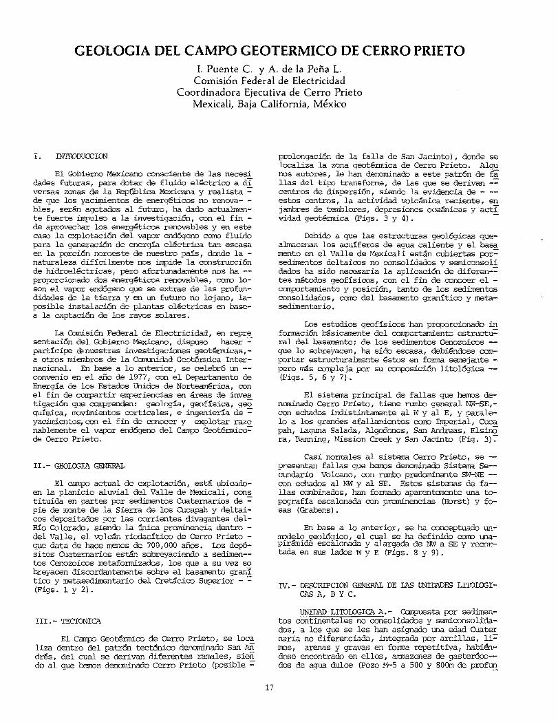
4. (A) M::x:1elo de fallas transfonres y centres de dispersion propuesto par Lomnitz et al. (1970) y Elders et al. (1972); (B), localizaci6n de estas fallas y centres en los Valles Imperial y Mexicali.

22
N E. U. A.
t:;. Zona d. Eatudlo
VIA FF. CC.
CARRETERA
~ FALLA DETECTADA POR SISMICA
2 :5 4 5 Km.- ESCALA GRAFICA
XBL 7811-12844
Figura 5. Plano de localizaci6n de lineas sismicas de refraoci6n.
23
LINEA N'
2100 2450
2300. 1000
2 &00 _UNDIDAD DEL REFRACTOR DE
;s 100 S 700 \Ee, (B~SAIIEII70' DE$
eOIiOCID~ E~ ESTA ZONA POR 2000 EXIlEDIR I'lE ~ PIDFUNllID~ M_
5700 ALCANZADA POR LA DISPOSICION
DE LAS ESTAQONES Y PUII70S DE TIRO (PROFUHDI DAD ESTIMADA DEL
8ASAII£II70 ! 5.000 METROS'
ICM.
LINEA N'1i!o e~RA£TERA A CANAL DE LOMAI LOS
o__SA_~~!-~E_L_IP_E____~::::::::~~::::::~r;,~C~ErR~~R:O~~~'I~7O::~~Il=E_RR~11O~~~~-=~:Il~~=F=F_CC~~=-_:J~~~____1006 Id 1700 "'1 ,I no /ldO
2000 2100 - 'T7!Slf __ 2400
2900 3100' -\ ------ _'"l1§!J 1000- 3200
\
2Q)()PROFUNDIDAD OIL IIt:f'RACTOR S700 MI.
SEe l8A8AMUTO', I'lESCONOCIDA III ElU •--------- .......... LADO DIL 8LOQIIE CAIOO DE LA FALLA
1000 :~~~:D~~::AD~L IASAMENTO \ POll EXIlEI'lER DE ~ PROFUNDIDAD IIAXIMA ALIlAIIZAOA.
\ \
1000.----~-~ ,° 15 Kit
8 o -.-------~- ____
1000
2000-. _ '700
PlDf'lJNOID~ DEL REf'RACTOII 5100 M~ [BASAMENTOI OUCONQIlIDA
EN ESTE LAIlO DEL 8LOQUE CAlOO DE LA FALLA, POR I!XCIOER DE ~ PROFUNDIDAD MAXIMA ALIlAIiZADA
lUI.
LIN E A N!' 4
8 CAML DE CERRO PIIIE10 VIA FF ec CANAL SOL FATARA
....._ .._______.____--"L.::""_ .... ___~ __ ...._-, ....... 20000-------·· ._~-__ ~s...L-=:-:::::. .. --.~ 2400 1950
1000- -3~~O---~------2400 ...r-------
\ 3000
2000
PROFUIIIlIDAD ESTIMADA PMAEL-iproo \
---~700 8ASAMEIITO EN 8A~E ALARE3000- ! , FLEXION MAS PROFUNDA QUE
t \' \ (E O&SERVO EN EL SISMOGRA\" MA I-II DEL m su
POIIIENDO URA VlLoCIDAD ME\
. orI 3000 "'18. PAIIA"A cu-I 81 ERTA SEDIMENTARIA \ 1- -
'''--'''''--'''-'' -.,---------
ESCAI.A GRAFICA
KM. XBL 7811-12845
6. Secciones sisrnicas de refracci6n 1, 2, 3, Y 4, zona de Cerro Prieto.

__ __ __ __ __ _____ __ ________
----
24
LIN EA
PR)F. Ell @ CAIIIIETERA A VIA F,F,ce, ®CR\lCECON LINEA 50!)
~ MnROS SAN FELIP,!) I0- . .
1000
24000 \\ -\\,----==----2600
\\ 2000 \ \.;-------:-
\\ 4000
KM,
LINEA N'6
®CANAL DI! ZONA DE MAN IFESTAc:tONI!lI /' CARRET'ERA A "';..!7'O--------------------~-~--~~PN~~~!~-a~---H-ID-R-O-~---L-E-S-D-E--TUUC_HEC ~# SA_N FEL_IP_[ ~_A~O,~M~ VIA~.L______
1700
2400 1000
3 $00
5700 5700 2000
KM.
LIN E A N' 7
CANAL DE CAllIlETlIlA A CEMO FI'IIE'lO ... SAN fELl PI!
0---:-=-='::!~7===;:;;;;;;::=··""'·....."---:-::-::-::--------:-=~-----'-·--------Z200 1700 1700 1700
2500
2<XlO570D
KM.
LIN E A N' 8
CDCIIUCI! CON CAIlRETIIIA A ~O M-4 V I A F.F. ce . .~_____U_N_I!AS'_1·.::b___________8AN__F_I!_L_I-"';.=;;>'--__________--'...r'________~*"'-"=____
1700
1000
2000
I 2 SOO1 ______-
f 5000
KM.
L I H E A HI' 9
VIA CC.
O-+-----------------~~------~ ---------------------~-----------------------
1000 2 SOD
5700 4000
II 000
3OOOrr------------ ----,------------- --- I I 10 IS KM,o
ESCALA (JRN'lCA
o , 2 ~
;--w IiiiI XBL 7811-12846
Figura 7. Secciones sismicas de refraccion 5, 6, 7, 8 Y 9, zona de Tule Check.
2S
n 5 10 km T..........' .......'
XBL 7811-12847A
Figura 8. Configuracion del basamento.
didad), clasificados cane del tipo (Alonso 1965). Al fondo y sobreyaciendo a B, se presentan regula.rmente capas de lutitas semicon solidadas de color cafe (Fig. 2).
Esta unidad A, por su estado no consolidadoy semiconsolidado, debe comportarse pUisticamenteal ocurrir rnoyimientos telUricos, los que al provo car fracturamientos en los sedimentos son r~pida-= rrente cerrados por las arcillas y arenas, no penni tiendo el asoenso de los £1uidos calientes que con tiene la simpre y cuando el de :: la V-A sea suficientemente grueso. espesor de esta unidad A varfa entre 600m (pozo M-I05) a 2215 (Pozo Prian 1) .
UNIDAD LI'IDIJJGIC'A B. - Esta fonnada por sedi rrentos deltaicos consolidados del continental y siendo su estratificaci6n en fonnalenticular•
De edad Terciaria {a13n no diferenciadal, esta integrada por una altemancia de lutitas, limolitas y areniscas. Las lutitas y limolitas van de color claro a obscuro y ocasionalrrente negras y en partes metam::>rfizadas.
Las areniscas son principalrrente de color -gris claro, de grano fino j-.i"'!n seleccionado casi ,.. siempre, variando entre grauvaca y arcosa, y ocasio na.i.nEnte a cuarcita (Pozo T~366) . -
Esta Vnidad B, por estar cornpletamente consolidada, ha sido posible observar tanto en los re cortes de perforacioo, cane en los nucleos,. las ...:.,:
huellas del fracturamiento que tienen las recas,como consecuencia de los efectos tect6nicos ocurri dos en la
Esta unidad es la que contiene entre sus 00rizontes pElnneables a los acuiferos de alta tenpe'ratura, considerando que las zonas fracturadas son los conductos principales por los cuales emigran los fluidos de agua caliente, dentro de la salmuera. Se estima su eSJ?E!sor entre 2000 a 250Om.
UNIOAD LI'IDIJJGIC'A C."" Se Ie ha denominado al basamento gran!tico y metasedimentario del eretacico SUpElrior, estando en superfi-
una mayor parte rocas que fonnan de los Cucapa. Esta Unidad C, que for
del batolito califomiano, ha sido perfosolamente en tres sitios en la zona geotermi
ca de Cerro Prieto, mediante los pozos M-3, S-262, Y H-96, a las profundicl.ades de 2547m, 1478rn y 2722 m., respectivarrente (Fig. 10).
De los resultados obtenidos mediante los estudios geoffsicos, asf corro de las perforaciones,heroos inferido, que los granfticos que for man el basamento en el .Mexicali fueron a= fectados por rrovimientos tect6nicos ascendentes ydesoendentes, siendo donde se perfor6 el pozo S- 262 un maximo exponente de los bloques tect6nicosascendentes, sitio en el cual se econtr6 el basa-mento a 1478rn de profundidad (Figs. B y 10) .
Los bloques predominantes ascendentes, se -alinean a un rum1.:o qeneral NW-SE (Fiqs. 8 Y 9), pa ralelos a la Sierra- de los Cucapa. --
@
0
., 1000 0..
I
'" lIE
2000
..'" .,
.,lI()(lO N
Z 0\::l ... 0 Ir
4000 Q.
5000
11000
S. dim /I n t 0 s 0/1 I to i cos no Con sol i d Q do. (Arcillos, Arena. y Grovo s , U-A ~{~ ZOllO d. 1.0. S/ldim.llfos Con.olidados Sumomente Fracturado
U-S -_ Sedimentos Deltaico, Consolidodo. ( I. u I i los. U m ", ito. Y A ren i.eas'
U-C - t:i,:,<,:!,:i'a Ro c CI G r CI II i tic a y Ailet05edimenlorio
o 5 10 km ~ Sedimelllos de Pi.d.monl. (Abonieo5 Aluvial.s' ! ! !~
XBL 798-10916
Figura 9. Corte sudoeste-nordeste.
~

--
NW
L5-4 o ,~
I
I!IOO U-A
- .......... ~ ..... -. -.-.-~*IOCOI • t
U-B I I I
zoool- t t I *>2!1OOi- I----_? ____II
x x x x x xx x
SE
LS-3 S-262101-' o I
I $COU-A I
t I _" . ...... . .... I ~~ -Hooo t --.........~:B ............ ····t~·· ..······ ...................... "" ........ .4.,.... " .-~ ?I .... '
.' ? .- -X - -- X X..... " I -- - X 7'11-x,ISOO
............. /. X X,~ ~ IX,,'/"'X X X X X X --x.--X-!_-X-- X X~ )lITe-'
....2000 X ... ' X X
'/')1 X X)( X.. .... / X X X X X _- X Xx XX X X X X X X X X Xx
X x x x x x X3CJ:l) , SOOOX xl/I N
--.]
? 3"Il00 3SOO
LS- PUNTO DE LA LINEA SISMICA DE REFRACCION ClONOE 5E DETECTO EL 8ASAMENTO
- ••• O' ••• ~. CONTI\CTO GEOLOGICO ENTRE LAS UNIOADES A , 8 INOEF1NIDO, TANTO POR
S 15MICA COMO POR PERFORACIONES
CONTACTO GEOLOGICO. /)I!FINIDO POR SISMICA
* CONTACTO PROYEC'DIDO, SEGUN LINEA SISMICA 4
o IlOO 1000",.
--i---' 8ASAMENTO ki;Ir.~X X
X
FALLAS SUPERFICIALES EN LOS LAOOS.!! , NO DEL VOLCAN DE CERRO PRIETO-;j; XBL 7811-12849A
Figura 10. Configuracion del ba.sa:m:mto en una seccion noroeste-sudeste en base a sismica de refracci6n y p::lZOS.
2500

28
En cambio hacia Salton Sea y el Cblfo de Ca,.. lifornia, los bloques tectOnicos tienden a descender en fonna escalonada y gradual, 10 misrro haciael NE y E del camp::> geotennico de Cerro Prieto, donde estos Ultim::>s y hacia el NE, tienen un signi ficativo descenso, el cual diversos investigadores basados en estudios grav:i.TrLetricos y magneticos, - han supuesto que el basamento este entre 6000 y 6500m de profundidad, esta anomal:La negativa se 1£ caliza en el Ejido Jalisco a 7 km. al NE 35° del pozo Prian 1, el cual lleg6 hasta 3500m de profun,.. didad, perforando solamente sec1:irrentos deltaicos (Fig. 13).
V. - CORRELACI0NE8 GEDI.03ICAS ENTRE :r..ru3 UNlDADESLI'IOI.03ICAS A, B Y C.
En base a las unidades 1itol6gicas antes des critas y detenninadas, en base a los recortes de -= perforaci6n, nucleos y la s1:smica de refraccion - (Figs. 6 y 7), se formaron secciones geol6gicas, ron el fin de tratar de ·analizar tanto el canporta miento estructural conn el espesor aproximado de -= los sedimentos Cenozoicos.
Para tal fin, se realizaron siete secciones ~ de rumba predominante NW-SE (Figs. 11, 12, 14, Y 15) Y cinco con rumba general SW-NE (Figs. 13 Y - 15) •
En un area central y limitada por los pows .. 7, ll4, 130, 10, 46, 45, 105, l8l, 9 y 43 (Figs. ,.. 11, 12 Y 13), se observa que la unidad litol6gicaA, tiene un espesor promedio entre 500 a 75Om. Ha cia el NE, SE Y el E, el espesor var1:a entre 1350iii (M-53} a 22l5m (Prian l). En cambio al NW (M-96,M-3) , al W (M-6) y al SW (8-262), esta unidad A de sedimentos arcillo-arenosos, no consolidados y sEmi ronsolidados, presenta entre 70% y 80% de sedimen--= tos arenosos e· intercalados entre ellos, delgados lentes de lutitas de color cafe y griS.
n= acuerdo a las cliferentes profundidades a las que se ha atravesado el contacto lito16gico entre las unidades A y B mediante los pozos que a la fecha se han construfdo, hanos considerado que esas diferencias dedesniveles, se deba a los efectos tee tOnicos, que en fonna ascendente y descendentes, -;: han afallado y fracturado tanto a las fonnaciones-sedimentarias, conn al basamento ~ fracturamientos que en parte se ha comprobado en los nucleos que se han obtenido de la unidad B, en los que se aprecian microfallas, fracturas y estructuras de hundimiento en las luUtas y areniscas.
En las secciones IV-IV', V..V' Y VI -VI' de :rumbo general SW-NE, se aprecia que la unidad A aumen ... ta de espesor hacia e1 NE y E Y por consiguiente el contacto con la unidad B se presenta mas profundo. Las diferencias de nive1es del contacto entre U-A y U-B en estas secciones, var1:a entre 5Om, (M.,.25 a M5), hasta 630m (M-lO aM-53), 10 que consideramos se deba al sistema de afal1amientos principa1es denaninado "Cerro prieto rt (A. Ca1der6n 1962), de :rumbo predaminante NN-8E, fonnando una estructura deltipo echelon, con echados al NE. Entre e1 t·1-53 y _. e1 pozo Prian l, la diferencia en e1 desnivel en e1 contacto U-A U-B, es de aproximadamente 150Om.
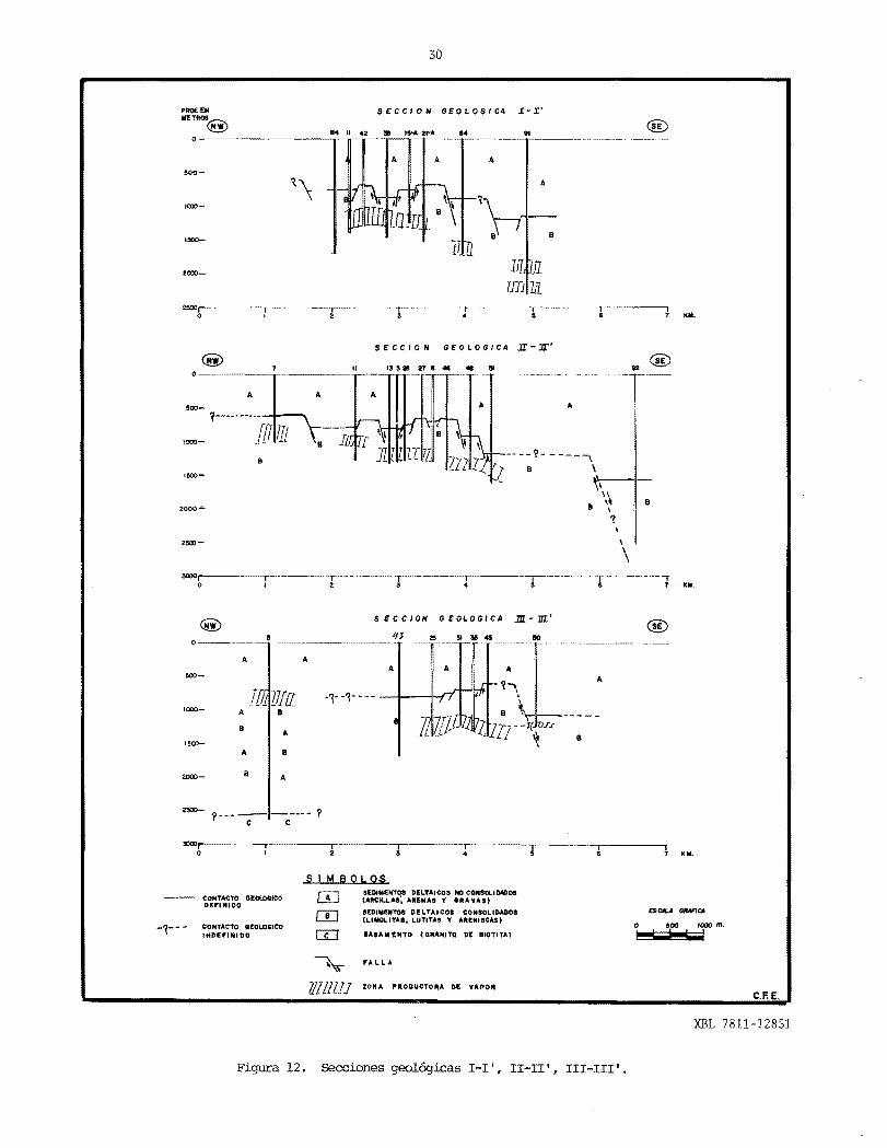
En las secciones I-I!, II-II', III-III', VII.... VII', VIII-VIII', IX .. IX', XI-XI', XII-XII', de :rum
bo NW-SE, se realizaron, con e1 fin de conocer la po sid6n y CCllllfOrtamiento estructural de los sedimen:= tos tanto hacia e1 moT cano al 8E, obserWindose y detenninanaose que se presenta un sistema de fa- llas casi nonnales al sistema principal, al cua1 10 denominamos sistema de fallas secundario "Vo1ca no" ( n= 1a pe:fia y Puente C., 1979).
Este sistema de fallas secundario de acuerdoa 10 observado, tambien tienden a CCllllfOrtarse en-fonna escalonada y descendente principalmente ha.!cia el 8 y 8E.
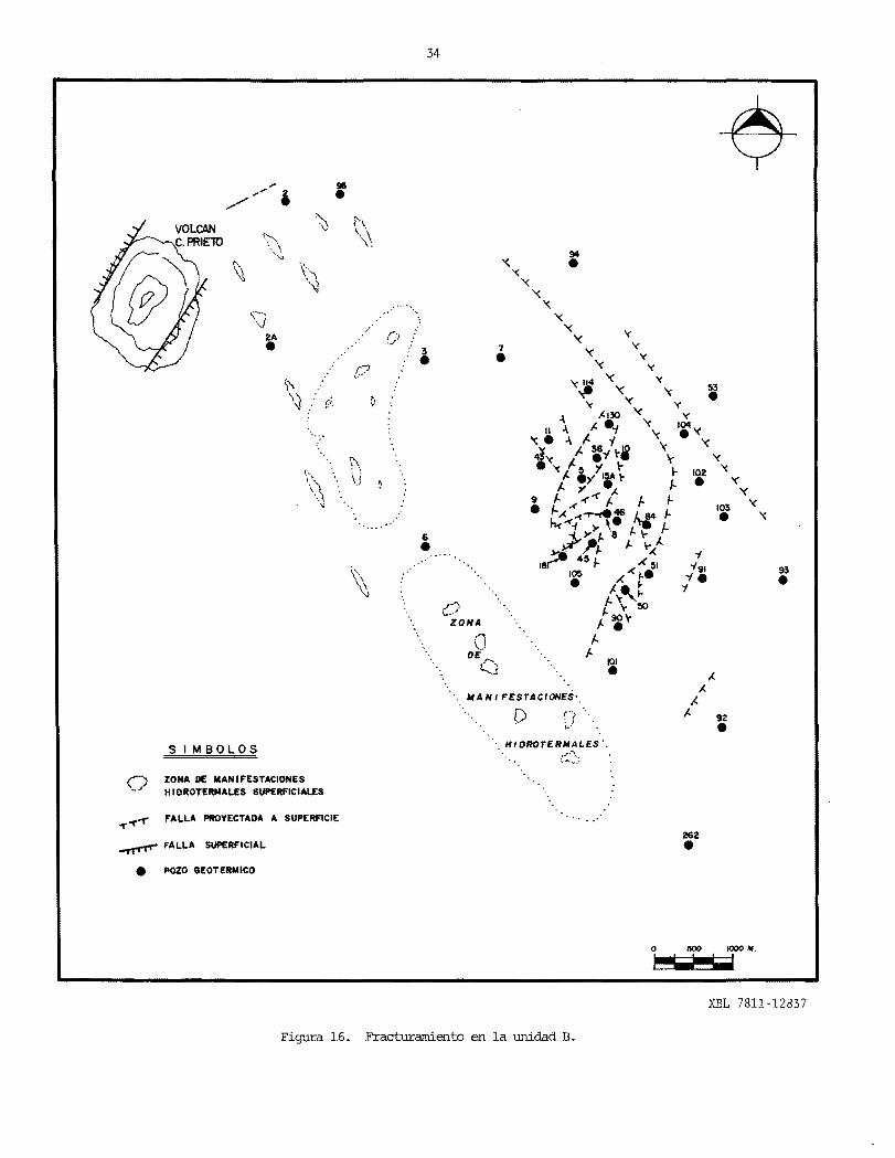
Con el fin de coroparar el fracturamiento de-terminado en las secciones geol6gicas, se realiz6una fotointerpretaci6n de la zona geote:rmica de Ce rro Prieto, con el fin de detectar fracturamientos superficiales (Fig. 17), los cuales compar~doloscon el fracturamiento obtenido en las secciones - que se proyectaron en planta (Fig. 16), notarros - que existe cierta concordancia del fracturamientoprofundo al fracturamiento que se presenta en la .. superficie.
IV. - cct·1PORI'M'lIENTO DE LA SAlMUERA DE ACUERIXl A LA PROFllNDlDAD DE EXPr.arACION DE LOS ACUIFEROS DE AGUA SOBROCALENTADA
En base al espesor de la U-A, conn de la profundidad de explotaci6n de los acufferos de agua sobrecalentada, contenidos en 1a salmuera (U-B), se ha dividido tentativamente el campo geotermicode Cerro Prieto en tres zonas de explotaci6n (Fig. 18).
ZO:iIA DE EXPr.a:rACION SOMERA:
Queda comprenclida desde 500m hasta 1000m de profundidad (pozo M-7, M-ll, M-9), as! conn tam- bien en los pozos lA, 2, M-3, M-6, M-96 Y S-262, en estos Ul tim::>s, se presentaron incranentos de - tanperatura muy superficial entre 100m y 300m de profundidad. Estas manifestaciones de temperatura superficiales detectadas en esos pozos, son debido a que esos sitios se perforaron aproximadamente un 80% de horizontes penneables (areniscas) y en un 20% de horizontes delgados de 1utitas y l0d0litas. En estos puntos e1 sel10 superior arci110-arenosoes muy delgado 6 no existe conn en la Laguna Vo1ca no y por eso se tienen manifestaciones hidroterrna= 1es superficiales.
A excepci6n de los pozos 7, 9 Y II que sf ~ perforaron e1 contacto litol6gico UA-UB, los res.,. tantes seis lA, 2, 3, 6, 96 Y 262, no atravesarondicho contacto, y tres de ellos llegaron al basamento granftico (3, 96 Y 262) a 2547m, 2722m y - l478rn, respectivamente (Fig. 10). Esto puede si9:. nificar que debido a los TIOvinl;tentoS ascendll"..n:1;':es-y descendentes de los b10ques tectOnicos, la salmue ra (UB) haya side oompletamente fracturada y afa-= llada 6 bien, que en esas zonas donde se presentan horizontes arenosos, sean qntiguas zonas costeras de una cuenca de depositaci6n 6 bien depasi tos de antiguos sistemas de pa1eccauses.

N- I
29
At!
XBL- 6711 12850
VOLCAN CERI'lO PIlIETO
2-A
•
SIMBOLOS:
96
•
... 3
«d---------b- SECCION GEOLOGICA
• POZO
o !lro 1000 N.
~
./ /'
PAl
Figura 11. Plano de localizaci6n de secciones geol6gicas.
30
SEC C ION G E 0 LOG I CA I - I'
®
A A
500-
''''''8
2000
TFD ill
SECCION GEOLOGICA JI-Jr'
II 15 sas 21.... .. .. o
A A A A~oo_
1-------·-~-
10 III'000
B
'50:)
2000':'"
250:)
\----v
1 . kM.
.m-.m'@ 0 ________.3
A A
rl -1- -1---Z7!{[.000- A 8
B A
I~ro-
SECCION GEOLOGICA
A B
2000- A8
1--------- '? c c
....
DELTAICOS Me C:ONSCLIDADOS C:ONTACTO GE«.Ocueo '( 911t"VAS)DEP'INIDO CSCA!.A _CA
DELTAICOI CONSOLIDADOI or ARENISCAS)
CONTACTO tl!OLOIICO o soo 1000 m. -~-- ntDIE,.,,.IDO
SEDIMENTOS (AJtCJLI..A.'~ ""fliNAe
SED'MENTOS (LIMOLITAI, LUTITAS
IAIAln"TO (GRANITO 01 BIOTITA) H;;J L;J
~ FALLA
llilllll ZONA PROOUCTORA DE VAPO~ C.F.E.
XBL 7811-12851
Figura 12. Secciones geol6gicas I-I', II-II', III-III'.

31
SE:CC/ON GE:OLOGICA JJ[- IE' PROF. EN IIETI<I>S VIA I'f'Ce
" D 2$ e 14 3_ 10 f' 104 '3@ •0--
I A A A A
500
A 8 1--
1000
8 A B
1500 A 8
~ I 1-\ A
717l t? !.l71l1 '~'---'\--4-~~ -8
]Jin.
2000
@
.,'OOr-·--- ----,--.-... - .... o I KII.
SE:CC/ON GEOLOGICA ]7-2"' @ VIA ~ 104 !'RIAl!105 45 4S
O-~~-
!500
2lXJO
.000
~~-~-
A
A - --- ?-"\
\ \ , A
\ , B ---1
EN ESTA ZONA SE SUPONE QUE
EL IIASAIIENTO 611ANITICO1
UTE £NTII! 5S00 A S_".
~
\--------- - -- -------- \~. 8
\ \
t 8 Kill.
A A
B8
!; K
SE:CC/ON GE:OLOGICA 1l1-Jll'
101 90
A
lizl flU?/;: II
A
B 8
_._...,.._---_ .. _--,._..... __ ._---_. .,. Kill.4
nCALA MAFICA SIMBOLOS
o IlOO /000 m. H;;;;;;J W
COOITACTO GE'OLO- SEDIMENTOS DELTAICOS NO CONSOL.IDAOOS0 G,eo CEI'INIDO (ARCILLAS, AII£IIA' l GRAYA_)
C!J SEDIMENTOS DEL TAICOS CO. SaLIDA DOS C ONTACTO eEOLO- U..IMOl.ITA9! LUTITAS '( AREN1SCAS)11100 IMDlPIlIlOO
~ FALLA
IllJl!l{[[ ION" PRQDUCTOftA DE VAPOR
XBL 7811-12834
Figura 13. Secciones geol6gicas IV-IV', V-V', VI-VI'.
I

32
PROF. EN SECC/ON GEOLOGICA :m'= MITROS NW SE
94 104 102 103 93 0
300
/000
2fXX}
~ A AA
i . - l' - \ ~ \
B B
II
2!JOO
'fCC/ON GfOLOGICA JnII-Y1lI' NW SE 114 130 10 84 51
0
K".
A A300
=-'rtf---:-\. -----:---\____________ A
_ 2000 B
21500
o • KY.
SfCC/ON GfOLOGICA :a:-1%'NW SE
2000_ I I I o S• 4• 7 KM.•
SIMBQLQS nO.NEII1tIS OELTAICOS 110 CONSDLIDAOOS
COIITACTO GEOLOGICO ill tAIICILL .... , ... IIEIIAI Y eRA v...11
m OH.NIOO nOINEIITOS DELTAICOS CONSOLII)ADO$ (LINOLITAI, LUTITAS ~ AIIENISC.... l
COIITACTO GEOLOGICO~ r--IIIOHIIIIOO m 'A LL A
0
500
1000
/300
1
A
\\1 II
A
l' B
1015
, \\
101
A
----1 B
262
A
A B
II A ~--• • •• • c c
XBL 7811-1283SA
Figura 14. Secciones geol6gicas VII-VII', VIII-VIII', IX-IX'.

33
SECCION GEOLOGICA X X'sw SE 262 92 95
0
500
A
1000
B A
/500- -;--;~.1I--~-------lI----- 'Z•
• •• I B 2000- e •
'\
3000r---------~----------TI--------~----------T,----------" o 2 4 I KN.
SECCION GEOLOGICA :zI-JI.' NW SE
III 91 93 0
500
/000'
1500
2000
A A
2500
KN.
SECCION GEOLOGICA :m-m'NW SE
94 0
500
IOQO
1!1OO
A
- I B
130 lI9 I5A 21A .6
A
If' I I
\~
B
A
- -
•
?
262
A
A
8 A
7---• r. • • e
S 1MB 0 LO S SlDINIM'108 OUTAleo. NO CONIOLIOADOIill (AIICILLAI. AItENA, Y GliAl/AS)
SEDINENTOI DtrLTAICoa eOlllOLIOADQS (LIIOOLITAI, LUTITAS Y AIIElllleAS)
CONTAeTo UOLOGICO '"01,,"100
-7-- ."'SANINTO UIIAIIITO 01 .'OTITAI
XBL 781l-12836A
Figura 15. Secciones geol6gicas X-X', XI-XI', XII-XII'.
34
"
•!IS
h \ \\
\ ....., \.1
•2A
f·
''\ "
•6
•93
,_? ZONA
\1 DE '"'-. ~j
MA N I FESTA ClONES'
C"/ " • • I....
.. HIDROTERMALES'.S I MBOLOS . : .....\
o ..... _.'
ZONA DE MANIFESTACIONES H' OROTERMALES SUPERFICIALES
FALLA PROYECTAOA A SUPERFICIE
...".rrr"' FALLA SUPERFICIAL 262•
• POZO GEOTERMICO
7•
94•
y y
y y
53•
101•
XBL 7811-12837
Figura 16. Fracturarniento en 1a unidad B.

3S
I /
/ /
"..:1 ;~ ;
'~ . .',? .,
"""- '" -- '"
ZONAS DE MANIFESTACIONES H IDROTERMALES SlFERFICIALES
FRACTURAMIENTO SUPERFICIAL
COrrf!tfra PAS
'" 3,,,"
5 PLANTA "• GEOT£RIoIOfLECTRICA
~ '" "" \:~ "
92•
• POZO GEOTERMICO
XBL 798-11026
Figura 17. Fracturamiento superficial en base a fotografias aereas.

36
ZI
/~-"""\\
~ //,. \/ \
/ \ \.// \
\ \
,: I I \
: I
~ I ZS \\
\
\,,?
\ \ \
I I I I \
ZI \
\ , "
\ \ ,
ZS
ZI
ZP
-_ ... -
•
\ \ ZS 'I. 93
'I. '. 105 o .5 1 km ,''I. , , . • '• ••11'._: \
\ " I\
'I. (I """" ZONA DE EXPLOTACION SOMERA " C'" I 101" , 'I.,, •
ZONA DE EXPLOTACION INTERMEDIA 'I., \ I \
ZONA DE EXPLOTACION PROFUNDA "\ '\, " ,,, 92•,, ''I.,LIMITE SUPUESTO , , ZP
'I. , \ ,
LIMITE DEFINIDO 'I. 'I., " , , , '
, IPOZO GEOTERMICO '\
", , o \ ZI 0 ZP ? , \,262•'\ I;."
E,\.;~ '\ ~ ,
'\ , J , C\.,,,---- ./
\ "'-- ..... \
\ I ; ZI
Carrelera PASCtJALlTOS - PESCADEROSI
. I
I
"
I
\
.. ," ~ , ZP \
? \
53•\ ZI \
\ \ \ \ \ \ \ 'I. ZP
\ ,,• ,
ZI •6 , 366,
XBL 798-11025
Figura 18. Zonas de explotacion.
37
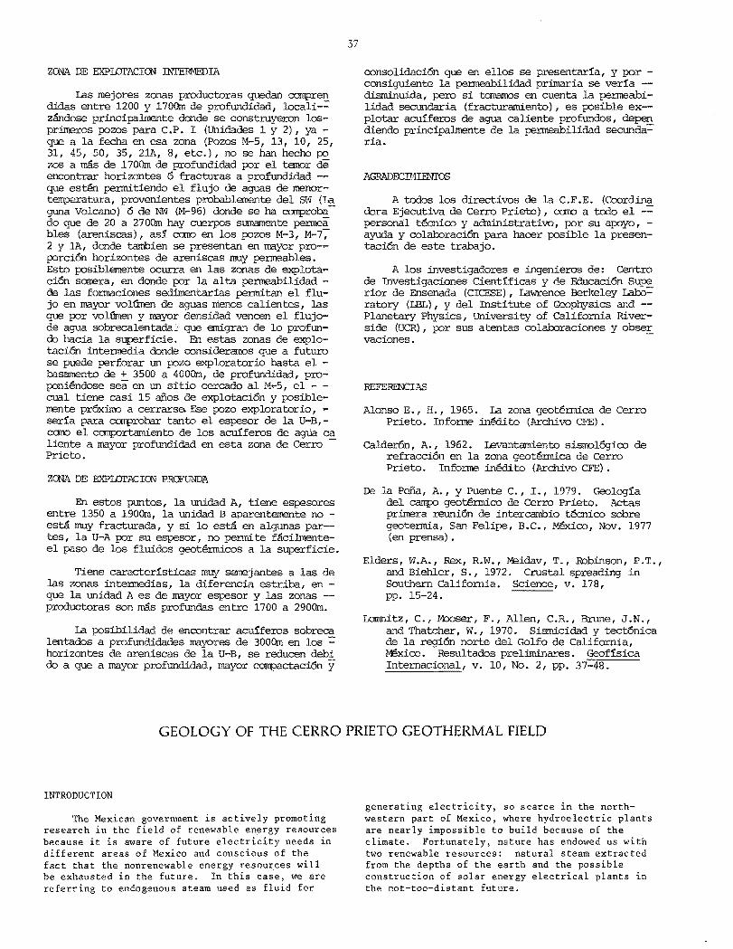
ZONA DE EXPIDI'ACION' INI'ERMEDIA
las mejores zonas productoras quedan COIlpren didas entre 1200 y 1700m de profundidad, locali-= zilndose principalmente donde se construyercn losprirreros pozos para C.P, I (Unidades 1 y 2), ya que a la fecha en esa zona (Pozos M-5, 13, 10, 25, 31, 45, 50, 35, 21A, 8, etc.), no se han hecho po zos a mas de 1700m de profundidad por el tanor de encontrar horizontes 6 fracturas a profundidad - que es~ permitiendo el flujo de aguas de menortemperatura, provenientes probablemente del 5'(", (la guna Volcano) 6 de NW (M-96) donde se ha COIlprobado que de 20 a 2700m hay cuerpos sumamente permea bles (areniscas), aSl carro en los pozos M-3, M-7-; 2 y lA, donde tarnbien se presentan en mayor pro-porci6n horizontes de areniscas rnuy permeables. Esto posible:nente ocurra en las zonas de explotaci6n sarrera, en donde por la alta permeabilidad de las formaciones sedimentarias permitan el flujo en mayor volUmen de aguas menos calientes, las que por volGmen y mayor densidad venoen el flujode agua sobrecalentada ';: que ernigran de 10 profundo hacia la superficie. En estas zonas de explotacioo intermedia donde consideraroos que a futuro se puede perforar un pozo exploratorio hasta el basamento de + 3500 a 400Om, de profundidad, proponiendose sea en un sitio cercado al M,..5, el - cual tiene casi 15 aiios de explotaci6n y posiblemente prOximo a cerrarse Ese pozo exploratorio, serfa para COIlprobar tanto el espesor de la U-B,como el camportamiento de los acufferos de agtia ca liente a mayor profundidad en esta zona de Cerro -Prieto.
ZONA DE EXPIDI'ACION PRCFUNDA
En estos puntos, la unidad A, tiene espesores entre 1350 a 19oOm, la unidad B aparentemente no est.a muy fracturada, y si 10 est.a- en algunas par-tes, la U-A por su espesor, no permite faci.lmenteel paso de los fluidos geot€onicos a la superficie.
Tiene caracterfsticas muy se:nejantes a las de las zonas inte:rntedias, la diferencia estriba, en que la unidad A es de mayor espesor y las zonas -productoras son mas profundas a'1tre 1700 a 290Om.
la posibilidad de encontrar acufferos sobreca lentados a profundidades mayores de 3000m en los = hori zontes de areniscas de la U-B, se reducen debi do a que a mayor profundidad, mayor compaetaci6n y
consolidaci6n que en ellos se presentarfa, y por consiguiente la penneabilidad primaria se verfa - disminuida, pero si tornamos en cuenta la permeabilidad secundaria (fracturamiento), es posible ex-plotar acuffercs de agua caliente profundos, depen diendo principalmente de la penneabilidad secunda= ria.
A todos los directivos de la C.F.E. (Coordina dora Ejecutiva de Cerro Prieto), care a todo el -= personal tOO1ico y administrativo, por su apoyo, ayuda y colaboraci6n para hacer posible la presentaci6n de este trabajo.
A los investigadores e ingenieros de: Centro de Investigaciones Cientfficas y de Educaci6n Supe rior de Ensenada (ClCESE), lawrence Berkeley Iabo= ratory (LBL), y del Institute of Geophysics and - Planetary Physics, University of california Riverside (UCR) , por sus atentas colaboraciones y obse£ vaciones.
REFERENCIAS
Alonso E., H., 1965. la zona geotennica de Cerro Prieto. Informe inMito (Archivo CFE) •
calder6n, A., 1962. Ievantamiento sismol6g"ico de refracci6n en la zona geotenuica de Cerro Prieto. Informe inedito (Archivo CFE) .
De la PeDa, A., Y Puente C., 1., 1979. Geologfa del campo geotermico de Cerro Prieto. Aetas primera reuni6n de intercambio tecnico sobre geotermia, San Felipe, B.C., Mexico, Nov. 1977 (en prensa) .
Elders, W.A., Rex, R. W., Meidav, T., Robinson, P. T . , and Biehler, S., 1972. Crustal spreading in Southern California. Science, v. 178, pp. 15-24.
Lomnitz, C., M:::x:lser, F., Allen, C.R., Brune, J.N., and Thatcher, W., 1970. Sismicidad y tect6nica de la regi6n norte del Golfo de California, Mexico. Resultados preliminares. Geoffsica Internacional, v. 10, No.2, pp. 37-48.
GEOLOGY OF THE CERRO PRIETO GEOTHERMAL FIELD
INTRODUCTION generating electricity, so scarce in the north
The Mexican government is actively promoting western part of Mexico, where hydroelectric plants research in the field of renewable energy resources are nearly impossible to build because of the because it is aware of future electricity needs in climate. Fortunately, nature has endowed us with different areas of Mexico and conscious of the two renewable resources: natural steam extracted fact that the nonrenewable energy resources will from the depths of the earth and the possible be exhausted in the future. In this case, we are construction of solar energy electrical plants in referring to endogenous steam used as fluid for the not-too-distant future.

38
On behalf of the Mexican government, the ComisiOn Federal de Electricidad invited other members of the international geothermal community to participate in our geothermal research. In 1977, an agreement was signed with the U.S. Department of Energy to share research experiences in geology, geophysics, geochemistry, subsidence, and reservoir engineering in order to establish the characteristics of the Cerro Prieto geothermal field.
GENERAL GEOLOGY
The present producing field is located in the alluvial plain of the Mexicali Valley and is made up in part of Quaternary piedmont sediments from the Cucapah Range, and in part by deltaic sediments deposited by the meandering currents of the Colorado River. The only prominent topographic feature in the Valley is the Cerro Prieto rhyodacitic volcano, which is less than 700,000 years old. The Quaternary deposits overlay metamorphosed Cenozoic sediments, which in turn are discordant on the granitic and metasedimentary Upper Cretaceous basement (Figures 1 and 2).
TECTONICS
The Cerro Prieto geothermal field is located within the San Andreas tectonic system, which can be divided into different segments: the geothermal area is situated along a segment we have named Cerro Prieto (a possible prolongation of the San Jacinto fault). Some authors have termed these segments transform faults, which connect spreading centers. The evidence of these spreading centers is recent volcanic a.ctivity, swarms of earthquakes, oceanic depressions, and geothermal activity (Figures 3 and 4).
Various geophysical methods had to be used to determine the attitude and layering of the consolidated sediments and of the metasedimentary or granitic basement, because the geological structures holding the hot-water aquifers and the basement of the Mexicali Valley are covered by unconsolidated and semiconsolidated deltaic sediments. Geophysical studies have supplied basic information about the structural behavior of the basement. Information about the overlying Cenozoic sediments has been scarce; it is assumed, however, that they have a similar but more complex structural behavior due to their lithologic composition (Figures 5, 6, and 7).
The principal fault system, which we have named Cerro Prieto, has a general northwestsoutheast strike, vertical offsets either to the east or west, and is parallel to such prominent faults as Imperial, Cucapah, Laguna Salada, Algodones, San Andreas, Elsinore, Banning, Mission Creek, and San Jacinto (Figure 3).
The faults that we have designated Secondary Volcano System, with a predominant southwestnortheast strike and vertical offsets to the northwest and southeast, are perpendicular to the Cerro Prieto System. The combined systems have
apparently formed a step faulted horst and graben topogra phy.
A geological model of the basement has been conceived, based on the preceding data. This model has been defined as a series of truncated and step-faulted pyramidal prisms, which are elongated and strike northwest-southeast (Figures 8 and 9).
GENERAL DESCRIPTION OF LITHOLOGIC UNITS A, B, and C
Lithologic Unit A
This unit is composed of unconsolidated and semi consolidated continental sediments of undifferentiated Quaternary age. It shows repeated sequences of clays, silts, sands, and gravels. Fresh water gastropod skeletons, classified as Amnicola (Alonso, 1965) have been found (well M-5 from 500 to 800 m depth). At the bottom of this unit, overlying unit B, semiconsolidated coffeecolored shale layers are usually present (Figure 2).
Unit A, being unconsolidated and semiconsolidated, must behave plastically under tectonic stresses. When the stresses create fractures in the sediments, they are rapidly closed by the clays and sands, not allowing the ascent of hot fluids, provided that this unit is thick enough. The thickness of unit A varies between 600 m (well M-I05) and 2215 m (well Prian 1).
Lithologic Unit B
This unit is formed by consolidated deltaic (continental) sediments generally presenting lenticular bedding. Of Tertiary age (as yet not differentiated) it is composed of alternating shales, siltstones', and sandstones. The shales and siltstones are partly metamorphosed and present light to dark grey, sometimes black, colors. The sandstones are light greyish, fine grained, usually well sorted varying between graywackes and arkoses, and sometimes quartzites as in well T-366.
Unit B, being totally consolidated, shows evidence of fracturing in the cuttings and cores caused by tectonic events that occurred in the region. This unit includes the hot aquifers among its permeable horizons. It is assumed that the fractured zones act as the main conduits for the migration of hot brines. Estimated thickness of this unit is between 2000 and 2500 m.
Lithologic Unit C
This basement unit corresponds to the Upper Cretaceous granitic and metasedimentary rocks outcropping in the Sierra Cucapa. Unit C, which forms part of the California batholith in the Cerro Prieto geothermal area, has been penetrated only at three points by wells M-3, S-262, and M-96 at 2547, 1478, and 2722 m, respectively (Figure 10).

39
From the results of geophysical studies as well as from the drilling program, we have inferred that the granitic blocks of the Mexicali Valley basement have suffered tectonic uplifts and falls. A good example of an uplifted block is shown at well S-262 where the basement was reached at a depth of 1478 m (Figures 8 and 10).
The predominant uplifted blocks have a general northwest-southeast strike parallel to the Sierra Cucapa (Figures 8 and 9). On the other hand, towards the Salton Sea and the Gulf of California, the tectonic blocks tend to be downthrown gradually and step-wise either to the northeast or east of the Cerro Prieto geothermal field. These downthrows are significant to the extent that several researchers have assumed, based on gravimetric and magnetic studies, that the basement is between 6000 and 6500 m deep. The negative anomaly is located at Ejido Jalisco, 7 km N 350 E of well Prian 1, which reached a depth of 3500 m, penetrating through deltaic sediments only (Figure 13).
GEOLOGIC CORRELATIONS BETWEEN LITHOLOGIC UNITS A, B, AND C
Based on the lithologic units described above, on the drill cuttings, cores, and refraction seismic data (Figures 6 and 7), cross sections were developed in order to analyze the structural behavior and determine the approximate thickness of the Cenozoic sediments. Accordingly, seven cross sections of predominant northwest-southeast strike (Figures 11, 12, 14, and 15) and five of southwest-northeast strike were developed (Figures 13 and 15).
In a central area bounded by wells 7, 114, 130, 10, 46, 45, 105, 181, 9, and 43 (Figures 11, 12, and 13), the lithologic unit A is observed to have an average thickness between 500 and 750 m. Toward the northeast, southeast, and east, the thickness varies between 1350 m (M-53) and 2215 m (Prian 1). On the other hand, toward th~ northwest (M-96 , M-3), west (M-6), and southwest (S-262), unit A is characterized by unconsolidated and semiconsolidated clayish-sandy sediments and is composed of between 70 and 80% sandy sediments with thin intercalations of coffee-colored and grey shale lenses.
According to the different depths at which the lithologic contact between A and B has been reached by the wells drilled to date, we have considered that the elevation differences are due to tectonic effects. These have faulted and fractured, upward and downward, the basement as well as the sedimentary formations. The fr~cturing has been confirmed by the cores obtained from unit B; microfaults, fractures, and subsidence structures have been observed in shales and sandstones.
In sections IV-IV', V-V', and VI-VI' of a general southwest-northeast strike, one can observe that unit A increases in thickness toward the
northeast and east. Therefore, the contact with unit B is found deeper. In these sections the elevation differences of the contact between units A and B vary from 50 m (M-25 to M-5) to 630 m (M-I0 to M-53). We believe these differences are due to the main Cerro Prieto fault system (Calderon, 1962) of northwest-southeast strike, which creates an echelon-type structure with downthrows toward the northeast. Between wells M-53 and Prian 1, the elevation difference of the A-B contact is approximately 1500 m.
Sections I-I', II-II', III-III', VII-VII', VIII-VIII', IX-IX', XI-XI', and XII-XII' of northwest-southeast strike were developed to determine the structural position and behavior of the sediments to the northwest as well as to the southeast. In this way, a secondary fault system, which we called Volcano, almost perpendicular to the main system, was determined (de la Pena and Puente C., 1979). According to what was observed this secondary fault system also tends to have a stepwise behavior, with downthrows mainly toward the south and southeast.
A photointerpretation study of the Cerro Prieto geothermal area was made to determine surface fracturing (Figure 17) and to compare with fracturing established by the geologic cross sections. When the deep fractures are projected in plan (Figure 16) a certain agreement with the surface fracture is noted.
BRINE BEHAVIOR ACCORDING TO THE PRODUCTION DEPTHS OF HOT AQUIFERS
Based on the thickness of unit A and the depth of production of the hot-water aquifers (unit B), the Cerro Prieto geothermal field has been tentatively divided into three production areas (Figure 18).
Zone of Shallow Production
This zone lies between 500 and 1000 m depth (as in wells M-7, M-ll, M-9). It is also observed in wells lA, 2, M-3, M-6, M-96 , and S-262 where temperature increases are observed at very shallow depths (between 100 and 300 m). The shallow hightemperature manifestations observed in these wells are caused by the presence of 80% permeable horizons (sandstones) and 20% thin shales and mudstone layers. At these well locations, the upper clay-sandy seal is very thin or does not exist at all, as at the Laguna Volcano, thus explaining the surface hydrothermal manifestations.
Wells M-7, M-9, and M-ll were drilled through the contact between units A and B; wells lA, 2, M-3, M-6 and S-262 were not. Three wells of the latter group reached the granitic basement (M-3, M-96, and S-262) at 2547, 2722, and 1478 m, respectively (Figure 10). This could mean that because of tectonic movements unit B has been completely fractured and faulted, or that the areas presenting sandy horizons are ancient coastal zones of a sedimentary basin or deposits of paleochannel systems.
40
Zone of Intermediate Production
The best producing zones are between 1200 and 1700 m depth, localized mainly where the first wells for power plant Cerro Prieto I (units 1 and 2) were drilled. To date, no wells have been drilled deeper than 1700 m (wells M-S, M-l3, M-lO, M-2S, M-3l, M-4S, M-SO, M-3S, M-2lA, M-8, etc.) because of our concern about finding horizons or fractures at depth that will allow the influx of colder water, probably originating from the southwest (near Laguna Volcano) or the northwest (near M-96). In well M-96 between 20 and 2700 m, very permeable layers (sandstones) have been found. In wells M-3, M-7, 2, and lA, a large percentage of the total thickness also consists of very permeable sandstone horizons. This influx possibly occurs in the zones of shallow exploitation where the high permeability of the sedimentary units allows larger volumes of colder waters to flow. These colder waters, because of their large volume and greater density, displace the hot water migrating upward from depth.
We are considering drilling a 3S00- to 4000-m-deep exploration well down to the basement in these zones of intermediate production. The site proposed is near well M-S, which has been producing for almost IS years and may be closed in the near future. The purposes of this exploratory well are to determine the thickness of unit B in this part of Cerro Prieto and the behavior of deeper hot-water aquifers.
Zone of Deep Production
In the zone of deep production, unit A has a thickness between l3S0 and 1900 m; unit B apparently is not very fractured. Even if unit A is fractured, it does not easily allow the flow of geothermal fluids toward the surface because of its thickness.
This zone has very similar characteristics to the intermediate production zone. The differences are that unit A is thicker and the producing zones are deeper between 1700 and .2900 m. The possibility of finding hot-water aquifers in the sandstone layers of unit B at depths greater than 3000 m is reduced because of their higher consolidation and compaction. Although the primary permeability would be reduced, production could depend on the existence of secondary permeability (fractures) which would allow us to exploit these deep hot-water aquifers.
ACKNOWLEDGMENTS
We acknowledge the support, help, and collaboration of all the officials of CFE (Coordinadora
Ejecutiva de Cerro Prieto) as well as of its technical and administrative personnel who made the preparation of this paper possible. We also thank the researchers and engineers of: Centro de Investigaciones Cientificas y de Educacion Superior de Ensenada (CICESE), Lawrence Berkeley Laboratory (LBL), and the Institute of Geophysics and Planetary Physics, University of California, Riverside (UCR) for their kind collaboration and observations.
FIGURE CAPTIONS
Figure 1. Geologic map of the Cerro Prieto area.
Figure 2. Generalized stratigraphic column of the Cerro Prieto area.
Figure 3. Regional tectonic map.
Figure 4. A, transform fault and spreading center model proposed by Lomnitz, et al. (1970) and Elders, et a1. (1972). B, location of these faults and centers in the Imperial and Mexicali Valley.
Figure S. Location map of seismic refraction lines.
Figure 6. Seismic refraction cross sections 1, 2, 3, and 4, Cerro Prieto area.
Figure 7. Seismic refraction cross sections S, 6, 7, 8, and 9, Tule Check area.
Figure 8. Basement configuration.
Figure 9. Southwest-northeast geologic cross section.
Figure 10. Northwest-southeast cross section showing basement configuration based on refraction seismic and well data.
Figure 11. Location map of geologic cross sections.
Figure 12. Geologic cross sections I-I', II-II', and III-III I.
Figure 13. Geologic cross sections IV-IV', V-V', and VI-VI'.
Figure 14. Geologic cross sections VII-VII', VIII-VIII', and IX-IX'.
Figure IS. Geologic cross sections X-X', XI-XI', and XII -XII' .
Figure 16. Faulting of unit B.
Figure 17. Surface faulting based on aerial photograph s.
Figure 18. Production areas.