Memorias Cache Arq. de Computadores Santiago González Tortosa.

Gabriel JiménezDpto. Arq. y Tec. de Computadores
ESI InformáticaUniversidad de SevillaUniversidad de Sevilla

¿Qué pretendemos?• Aprender a diseñar STR sencillos de forma rápida• Aprender a diseñar STR sencillos de forma rápida
empleando elementos “open source”.• Diseñar periféricos que puedan conectarse a un PC
(windows, linux, OS X) conectándose medianteUSB.
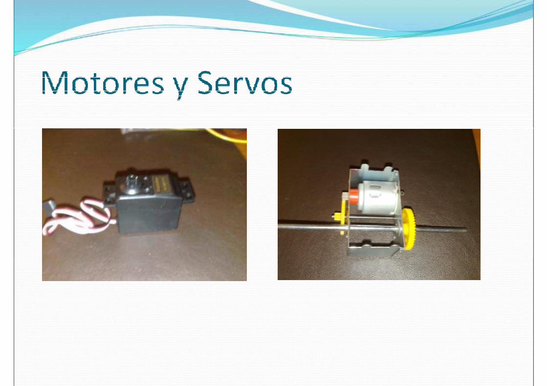
• Conectar periféricos sencillos como: LEDs, Potenciómetros, PIRs, Servos, Motores DC, Potenciómetros, PIRs, Servos, Motores DC, sensores Piezoeléctrocos …

Agenda:• Día 1:
• Descripción del material.• Instalación sistema desarrollo.• Instalación sistema desarrollo.• Estudio de esquemas y conexión de dispositivos
externos. • Hacer el primer ejemplo, debug …
• Día 2: Sensores y actuadores (PWM, servos, LCD, sensores piezoeléctricos).
• Día 3: Conexión USB, dispositivos clase audio.• Día 3: Conexión USB, dispositivos clase audio.• Día 4: Conexión USB dispositivos clase HID y clase
especídica fabricante.• Día 5: Conexiones inalámbricas baja velocidad
(Zigbee)

Entorno Hardware• Atmel 91SAM7x256 (ARM7)• Atmel 91SAM7x256 (ARM7)• Make controller y Make application board (placas de
desarrollo de Makingthings. Tienen varias ventajas:o Totalidad de Esquemas disponibles.o Interfaces para:
� 8 entradas analógicas.� 8 salidas digitales (con medio puente en H) hasta 1Amp.
� Agrupables de 2 en 2 para motores DC y de 4 en 4 para � Agrupables de 2 en 2 para motores DC y de 4 en 4 para paso a paso.
� 4 salidas para servos (aeromodelismo).� SW+LEDs+Pot


-Basado en FTTD-Soportado en OpenOCD-Soportado también por Xworks-Incluye USB/serie-Incluye DC-DC


• Basado en FreeRTOS• USB CDC• USB CDC• Compilable con Herramientas Públicas
o Cadena GCC (yagarto)o Open OCDo Eclipse
• Se configura mucho más fácilmente con CrossWorks.CrossWorks.
• Para prototipado rápido de periféricos incluyeinterpreteOSC en la Configuración por defecto (Heavy).
• OSC usable desde cualquier lenguaje de alto nivel.• Librerías para facilitar el uso en .NET (C#).

-OSC provides an intuitive way to organize the elements on the board,and specify which messages go to which parts of the board.-OSC messages for the Make Controller Kit all look similar - they specify an address , and then give the value that should be sent to that address.an address , and then give the value that should be sent to that address.They adhere to the format of:
/subsystem/device/property argument
-Subsystems are different elements of the board - analog inputs, LEDs, digital outputs, servos are all examples of subsystems. Each of these subsystems has a number of Devices - 8 analog ins, 4 LEDs, 1 dipswitch.- Properties - there are several different properties of the servo, for - Properties - there are several different properties of the servo, for example, that we might want to set - the speed, the position, etc. For the LEDs, this would be their on/off state, and for the analog ins it would be the value. Finally, the - Argument is the value that should be sent to the address specified by the subsystem, device, and property.

For reading values, you have two options:Send a request message to the board for the value you want to read, and the board sends a message back, with the requested value. and the board sends a message back, with the requested value. Configure the board to automatically send any new messages back to you as they are generated.first method: Write messages include an argument value, as in the example above. If a message doesn't include an argument, then the board interprets it as a request.ExampleSo, to tell the board to turn on LED number one on the Application board, we would send the messageboard, we would send the message/appled/1/state 1

FreeRTOS en Make• Documentación Incluida con los fuentes del • Documentación Incluida con los fuentes del
firmware (abrir \doc\index.html)• Variaciones sobre FreeRtos standard (algunos
cambios de nombre fundamentalmente).• Cuando la placa arranca llama a la rutina que
inicializa el hardware y después crea la tarea run().• En run() se inicializan los principales subsitemas y • En run() se inicializan los principales subsitemas y
se crea la tarea que hace parpadear el LED. Podemos crear una tarea similar para hacer lo que queramos.
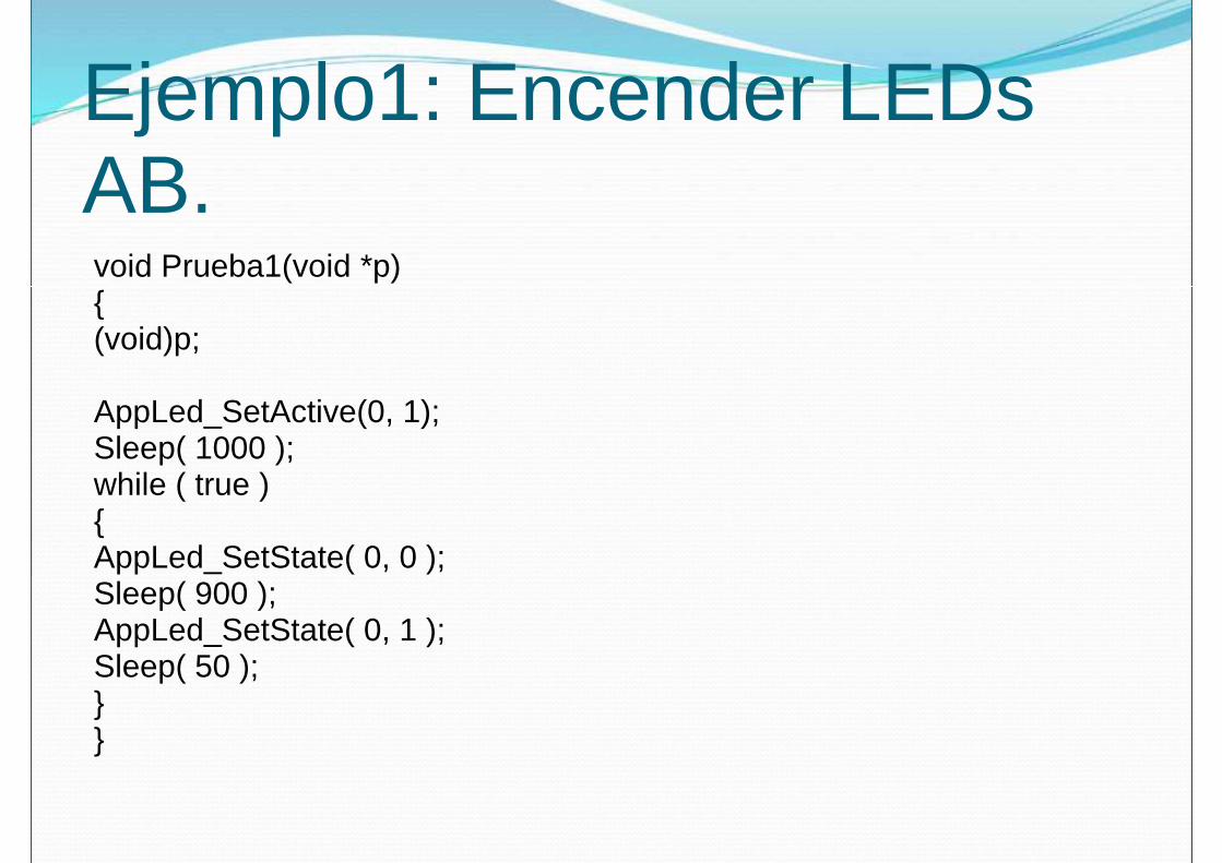
Ejemplo1: Encender LEDs AB.void Prueba1(void *p){{(void)p;
AppLed_SetActive(0, 1);Sleep( 1000 );while ( true ){AppLed_SetState( 0, 0 );Sleep( 900 );Sleep( 900 );AppLed_SetState( 0, 1 );Sleep( 50 ); }}

Ejercicios.1.Leer un potenciómetro y colocar un servo en la 1.Leer un potenciómetro y colocar un servo en la
posición indicada por este (periodicidad 0,1s).2.(3 Tareas)
1.Lee un potenciómetro (velocidad servo) y manda su valor a la otra tarea mediante una cola.
2.Lee un potenciómetro (posición servo) y manda su valor a la otra tarea mediante una cola.
3.Lee las dos colas y controla el servo3.Lee las dos colas y controla el servo• El código de T1 y T2 es el mismo. A la hora de
crearlas se les pasan parámetros para diferenciarlas.

Ejercicio3• Se trata de uno de los sistemas típicos en • Se trata de uno de los sistemas típicos en
concursos de TV. Hay dos concursantes cada uno tiene tres LEDs y un botón. Inicialmente para cada concursante un led empieza a parpadear cada vez más rápido. Cuando termina se enciende un segundo LED indicando que ya se puede accionar el pulsador. Tras esto el servo señalará al el pulsador. Tras esto el servo señalará al concursante que ha pulsado primero.
• Si alguien pulsa antes de tiempo queda invalidado y se le encenderá su led de descalificado.

FREERTOS• FreeRTOSConfig.h• Tareas
• vTaskStartScheduler• vTaskStartScheduler• vTaskEndScheduler• xTaskCreate• vTaskDelete• taskENTER_CRITICAL• taskEXIT_CRITICAL
• Colas• xQueueCreate• xQueueCreate• xQueueSen• xQueueReceive
• Semaforos• vSemaphoreCreateBinary• xSemaphoreCreateMutex
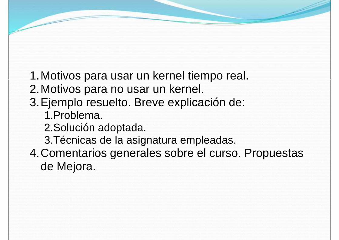
1.Motivos para usar un kernel tiempo real.1.Motivos para usar un kernel tiempo real.2.Motivos para no usar un kernel.3.Ejemplo resuelto. Breve explicación de:
1.Problema.2.Solución adoptada.3.Técnicas de la asignatura empleadas.
4.Comentarios generales sobre el curso. Propuestas de Mejora.de Mejora.