![CALIFATO Y RELIGIÓN. LAS SORPRENDENTE … · Arab culture, while al-Ma'mun, ... [Consultad 3 dea marzo el 2006], . RUIZ: CALIFAT YO RELIGIÓN.. 651 ... dable (a Dios) de cas laa](https://static.fdocuments.ec/doc/165x107/5b949f3909d3f2bd1e8db37e/califato-y-religion-las-sorprendente-arab-culture-while-al-mamun-consultad.jpg)
ESCUELA POLITÉCNICA NACIONAL - Repositorio...
251
ESCUELA POLITÉCNICA NACIONAL ESCUELA DE INGENIERÍA DISEÑO DE UN ACCIONAMIENTO REMOTO DE EMERGENCIA PARA LA COMPUERTA DEL CANAL DE ALIMENTACIÓN PARA LA CENTRAL HIDRÁULICA ALAO CON RTUs SIEMENS PROYECTO PREVIO A LA OBTENCIÓN DEL TITULO DE INGENIERO EN ELECTRÓNICA Y CONTROL RAMIRO EDUARDO CORDÓN SALGADO DIRECTOR: ING. PATRICIO CHICO Quito, Noviembre del 2001
Transcript of ESCUELA POLITÉCNICA NACIONAL - Repositorio...
ESCUELA POLITÉCNICA
NACIONAL
ESCUELA DE INGENIERÍA
DISEÑO DE UN ACCIONAMIENTO REMOTO DE EMERGENCIA PARA LA
COMPUERTA DEL CANAL DE ALIMENTACIÓN PARA LA CENTRAL
HIDRÁULICA ALAO CON RTUs SIEMENS
PROYECTO PREVIO A LA OBTENCIÓN DEL TITULO DE INGENIERO
EN ELECTRÓNICA Y CONTROL
RAMIRO EDUARDO CORDÓN SALGADO
DIRECTOR: ING. PATRICIO CHICO
Quito, Noviembre del 2001

DECLARACIÓN
Yo Ramiro Eduardo Cordón Salgado, declaro bajo juramento que el trabajo aquí
descrito es de mi autoría; que no ha sido previamente presentada para ningún
grado o calificación profesional; y, que he consultado las referencias
bibliográficas que se incluyen en este documento,
A través de la presente declaración cedo mis derechos de propiedad intelectual
correspondientes a este trabajo, a la Escuela Politécnica Nacional, según lo
establecido por la Ley de Propiedad Intelectual, por su Reglamento y por la
normatividad institucional vigente

CERTIFICACIÓN
Certifico que el presente trabajo fue desarrollado
por el Sr. Ramiro Eduardo Gordón Salegado bajo
mi supervisión.
'atricio ChicoDirector

DEDICATORIA
A mis padres que hicieron posible que
culmine mis estudios y a mi esposa e hijos
que me apoyaron durante la realización de
este trabajo.

AGRADECIMIENTO
AI Ing. Patrico Chico por su colaboración y
consejos que han contribuido al perfeccionamiento
de este trabajo.

CONTENIDO
Pag.
RESUMEN 1
PRESENTACIÓN 3
1.1 DEFINICIÓN Y CAMPO DE LA TELEMETRÍA 5
1.2 TENDENCIAS Y REQUERIMIENTOS DE LA INDUSTRIA EN 7
TELEMETRÍA
1.3 TECNOLOGÍAS DE COMUNICACIÓN UTILIZADAS EN 10
TELEMETRÍA
1.4 TÉCNICAS DE COMUNICACIÓN UTILIZADAS EN 15
TELEMETRÍA
1.5 TÉCNICAS DE RECOLECCIÓN DE DATOS 18
1.5.1 Técnicas de "PoIIing" 18
1.5.2 Polling con Técnicas de excepción 19
1.5.3 Reporte no solicitado con técnicas de excepción 20
1.6 TELEMETRÍA Y TELEMANDO 21
1.7 PROTOCOLOS 23
II SINAUT: SISTEMAS DE TELEMETRÍA SIEMENS
2.1 BREVE REVISIÓN DEL SISTEMA DE TELEMETRÍA 26
2.1.1 Características generales del sistema 26

Pag.2.1.2 Estación de Telecontrol SINAUTST100 28
2.1.3 Estación de Telecontrol SINAUTST115 31
2.2 SOFTWARE STANDARD DE LAS RTUS: SiNAUT 33
2.2.1 Procesamiento de datos en la Estación de Telecontrol 34
2.3 TIM: MÓDULOS DE INTERFACES DE TELECONTROL 37
2.3.1 TIM 11 37
2.3.2 TIM 01 IB 38
2.3.3 Los TIMs y las tecnologías de comunicación 38
2.3.4 Datos adicionales sobre los TIMs 39
2.4 PROTOCOLO SINAUT ST 40
2.4.1 Modo de PoIIing 41
2.4.2 Modo Cíclico 41
2.4.3 Modo Espontáneo 41
2.4.4 Proceso de compilación, transmisión y recepción 42
2.4.5 Tipos de datos 42
2.4.6 Mensajes 43
2.4.6.1 Mensajes de solicitud general y específica 45
2.4.7 Modo o técnica, de recolección de datos "polling" 46
2.4.7.1 Ciclo principal y secundario 49
2.4.7.2 Polling continuo 49
2.4.7.3 Comportamiento cuando falla la comunicación 50
2.4.8 Estructura de los mensajes en el protocolo SINAUT ST 50
2.4.8.1 Estructura del mensaje de datos 51
2.4.8.2 Estructura del mensaje de "polling" 51
2.4.8.3 Estructura del mensaje de "acuse recibo" 51
2.5 ESTRUCTURAS DE RED 53
2.5.1 Conexión Punto a Punto 53
2.5.2 Red Multipunto 53
2.5.3 Red en Estrella 54
2.5.4 Redes Telefónicas Públicas 55

Pag.PLANTEAMIENTO DEL PROBLEMA
3.1 DESCRIPCIÓN DEL PROBLEMA 56
3.1.1 Situación geográfica 56
3.1.2 Descripción del problema 58
3.1.3 Hipótesis del trabajo 63
3.2 REQUERIMIENTOS DEL SISTEMA 65
3.2.1 Requerimientos técnicos 66
IV DISEÑO DEL SISTEMA
4.1 PRELIMINARES 69
4.1.1 Descripción del Sistema propuesto . 69
4.1.1.1 Criterios para la configuración básica de las Estaciones 69
4.1.1.2 Criterios para escoger la tecnología de comunicación 73
4.1.1.3 Respaldo de energía 74
4.1.1.4 Tipo de accionamiento para la compuerta 75
4.1.2 Requerimientos de los posibles usuarios 76
4.2 DISEÑO 77
4.2.1 Diseño de los tableros de las RTUs 77
4.2.1.1 Dimensionamiento de las RTUs 77
4.2.1.2 Diseño de los tableros (equipo adicional) 86
4.2.2 Requerimientos técnicos de la instrumentación 93
4.2.3 Requerimientos técnicos del medio de comunicación 101
4.2.4 Diseño del accionamiento mecánico de ¡a compuerta 105
4.2.5 Diseño sistema de respaldo de energía para tableros 106
4.2.6 Dimensiones de los tableros 107
4.2.7 Flujogramas básicos de la programación de las RTUs 108
4.2.7.1 Flujograma de la Estación Maestra 109
4.2.7.2 Flujograma de la Estación de Tanque de Balance 110
4.2.7.3 Flujograma de la Estación de Ishpe 111

Pag.4.3 PLANOS 112
V CONCLUSIONES Y RECOMENDACIONES 126
BIBLIOGRAFÍA 130
ANEXOS
A Presupuesto Referencia! 133
B Esquema solución mecánica para el accionamiento 135
C Tareas a programar en las RTUs y definición de bits en el 138
tráfico de datos
D Hojas de datos del Sistema SINAUT - 146
E Hojas de datos de los equipos que se pueden utilizar 203
F Certificado 253
RESUMEN
Este trabajo está orientado a solucionar un problema práctico, que es el tipo de
problema que comúnmente afrontará cualquier egresado de una carrera de
Ingeniería en Electrónica y Control en su vida profesional en un medio de trabajo
como el que se presenta en nuestro país donde no tenemos tecnología propia.
Por lo tanto debemos utilizar y acondicionar los conocimientos y las técnicas
desarrolladas en otros países para dar las mejores soluciones posibles a dichos
problemas.
En el capítulo I se realiza un estudio breve de la tecnología de Telemetría y
Telecontrol que servirá como fundamento para encontrar la solución al problema
planteado. Se revisan algunos campos de acción que cubren estos sistemas, lo
que la industria mundial requiere de esta tecnología, las técnicas y tecnologías de
telecomunicación que usan estos sistemas, técnicas de recolección de datos
remotos disponibles y los protocolos de comunicación que usualmente- están
disponibles en los sistemas de telemetría.
El capítulo II está dedicado a un detenido estudio del sistema SINAUT ST
desarrollado por la empresa de productos y sistemas electrónicos Siemens AG de
Alemania. El estudio abarca una revisión general del sistema, del software,
hardware y firmware que constituyen el sistema sobre todo los procesadores de
comunicación que establecen el enlace entre las RTUs y el medio de
comunicación. También se hace una descripción del funcionamiento del protocolo
SINAUT y una rápida visión de la topología de redes de telemetría y telecontrol
que se pueden construir con este sistema.
En el capítulo III se plantea el problema que es motivo de este trabajo, se ubica
geográficamente el lugar donde el caso planteado se produce, luego se describe
todos los aspectos del problema resaltando las condiciones humanas, técnicas y
Resumen Pap. 2
geográficas del entorno para finalmente plantear la solución y los requerimientos
básicos que esta debería cumplir.
Basados en los requerimientos básicos que se plantean en el capítulo III, a lo
largo del capítulo IV se procede al diseño del sistema de Telemetría y Telemando.
Para ello se hace una descripción del sistema propuesto que naturalmente estará
basado en SINAUT ST, dejándose planteado los criterios con los que se
dimensionará las estaciones de telemando, el medio de comunicación entre las
estaciones y el sistema de accionamiento de la compuerta. Así mismo se remarca
los requerimientos desde el punto de vista de los usuarios. Luego, se pasa ya al
diseño del sistema empezando por el dimensionamiento de las estaciones de
telecontrol, pasando por el medio de comunicación, el respaldo de energía, la
instrumentación y se determinan las características técnicas de los diferentes
elementos y dispositivos del sistema. Respecto al accionamiento mecánico se
llega a dejar los requerimientos básicos que debería cumplir el accionamiento
para acoplarse al sistema de control de manera de formar un todo efectivo en el
caso de emergencia.
El capítulo V está destinado a las conclusiones, aportes y recomendaciones en
función del trabajo abordado en esta tesis.
En el Apéndice se adjuntarán catálogos y folletos de SINAUT ST y de algunos
elementos comerciales que pueden utilizarse en la construcción del sistema.
Estos documentos permitirán aclarar y aumentar los conocimientos del lector que
desee profundizar sobre el tema.

PRESENTACIÓN
En el año de 1987, ya hace 14 años, egresé de la Facultad de Ingeniería. En ese
entonces mi idea de realizar un trabajo de Tesis de Grado era realizar un diseño y
construcción espectacular que demostraran en forma práctica todos los
conocimientos adquiridos en la E.P.N. El resultado fue que debido a la falta de
recursos económicos y a las limitaciones técnicas, ese trabajo se convirtió en una
tarea interminable. Hoy, luego de estos años de práctica laboral y ejercicio de la
profesión esa idea ha cambiado. Por ese motivo, este trabajo esta orientado a
solucionar un problema práctico, que es el tipo de problema que comúnmente
afrontará cualquier egresado de una carrera de Ingeniería en Electrónica y
Control en su vida profesional, donde deberá utilizar y acondicionar los
conocimientos y las técnicas desarrolladas en otros países para dar las mejores
soluciones posibles a dichos problemas.
El trabajo desarrollado en esta Tesis de Grado está basado en un diseño
realizado por mi persona (ver certificado en Anexo F) para la construcción de un
sistema similar, el cual fue instalado y funciona satisfactoriamente. Sin embargo,
se han incorporado mejoras en el diseño descrito en las siguientes secciones
para perfeccionarlo, basándose en los problemas y soluciones que se adoptaron
en la ¡mplementación práctica del proyecto.
Se espera que la principal contribución de este trabajo sea el trasmitir al lector la
experiencia adquirida a través de los años y en el mundo real, así como
concienciar a los nuevos egresados para que en su vida profesional utilicen todos
los recursos que ponen a su disposición las diferentes técnicas desarrolladas en
países donde se realiza investigación con suficientes recursos económicos y
técnicos; tratando de no desperdiciar los pocos recursos de Nuestro País en

Presentación Pag. 4
investigar temas que ya han sido suficientemente desarrollados en otros sitios del
mundo y que ya están a nuestra disposición.

CAPITULO 1
INTRODUCCIÓN A SISTEMAS DE TELEMETRÍA
1.1 DEFINICIÓN Y CAMPO DE LA TELEMETRÍA.
La Telemetría es un mecanismo por el cual se intercambia información con
localizaciones ubicadas a gran distancia (remotas) con el propósito de realizar
control y monitorización. Ha tenido amplia aplicación en las más variadas
industrias. Esta técnica cubre en complejidad desde sistemas con algunas
entradas y salidas para monitorización hasta el control de sistemas de
lanzamiento de naves espaciales y su funcionamiento en órbita.
Los componentes claves de un sistema de telemetría son:
• Las RTU (Remote Terminal Unit),
• Los sistemas SCADA (Supervisory Control and Acquisition),
. Los protocolos de comunicación y la red física de comunicación.
DEFINICIÓN DE RTU Y SCADA.
La RTU es un dispositivo remoto, el cual es responsable por la adquisición de la
información "real" desde los equipos de campo. Prepara, y en algunos casos
interpreta, los datos de los equipos de campo y los pone en el formato del
protocolo de comunicación, listos para ser trasmitidos por el medio físico de
comunicación1. Las RTUs pueden recibir la información a través de señales
eléctricas conectadas directamente a ellas o por medio de un enlace serial de
datos desde dispositivos con mayor inteligencia. También pueden realizar
funciones de control local.
Un sistema SCADA comprende uno o más computadores, proveyendo una

Introducción a Sistemas de Telemetría Pag. 6
¡nterface a la red de comunicación física y por lo tanto a las RTUs, así como
también a los operadores para que estos puedan mirar los datos enviados por las
RTUs1.
Estos datos pueden ser modelados, almacenados para una recuperación
posterior, analizados y transferidos hacia otros sistemas. Muy frecuentemente, un
sistema SCADA provee una interface de control para enviar datos a las RTUs:
puede ser por medio de comandos del operador, secuencias automáticas
desencadenadas como respuesta a los datos enviados desde las RTUs o desde
otros sistemas.
DEFINICIÓN DE PROTOCOLO Y RED DE COMUNICACIÓN.
Los protocolos de comunicación son los lenguajes usados para transmitir y
recibir datos por la red de comunicación física1. Un protocolo puede definir quien
envía los datos, el significado del mensaje enviado, verificando además la
información para asegurar que llega completa y que está libre de errores. Tanto el
receptor como el transmisor de los mensajes deben usar el mismo protocolo de
manera que puedan entender los mensajes enviados.
La red de comunicación facilita el medio físico para la transferencia de ía
información: desde una RTU al sistema SCADA, desde una RTU a otra RTU y en
algunos casos entre sistemas SCADA1. Hay un gran número de tecnologías
utilizadas para redes de comunicación en telemetría. El tipo de red que se escoja
para un sistema de telemetría, en una aplicación determinada, es crítico para la
operación del mismo y puede determinar su costo.
La red y la técnica escogida para el sistema de telemetría pueden tener un gran
impacto en la velocidad y efectividad con que este entrega los resultados, por eso
al diseñar una aplicación se debe tener mucho cuidado al escoger la tecnología
usada en los diferentes niveles.

Introducción a Sistemas de Telemetría Pap. 7
1.2 TENDENCIAS Y REQUERIMIENTOS DE LA INDUSTRIA ENTELEMETRÍA
En esta sección se explica los requerimientos y tendencias en telemetría. La
industria de Tratamiento de Aguas y de la Electricidad son algunas de las que
más han generalizado el uso de estos sistemas. Sin embargo, existen otras
industrias en las cuales se utiliza telemetría como son las de distribución de gas,
derivados, petróleo, etc.
Cada industria y aplicación tienen sus propios requerimientos, no obstante la
mayoría de ellos son satisfechos con la tecnología actualmente disponible.
Existen en el mercado sistemas que disponen de una gran flexibilidad en lo que
se refiere a las técnicas comunicación, protocolos, expandibilidad y capacidad de
control, por lo que pueden tener una amplia gama de usos.
EN EL CAMPO DE LA DISTRIBUCIÓN Y TRANSMISIÓN ELÉCTRICA
Los requerimientos de la industria en este campo incluyen suministro continuo,
seguridad, bajos costos de producción y distribución, interoperabilidad entre
sistemas, etc. Los sistemas de telemetría han contribuido a cumplir con este
objetivo.
La industria de la electricidad usa RTUs de gran capacidad, en sitios como las
subestaciones donde se tiene gran cantidad de entradas y salidas provenientes
de interruptores y alimentadores. La tendencia más reciente es hacia el uso de
enlaces de datos con instrumentación inteligente (basada en microprocesadores)
lo que reduce la cantidad de entradas/salidas que deben disponer las RTUs. La
información que se puede recuperar de este tipo de instrumentación por medio de
un canal de comunicación serial tiene alta resolución, es en tiempo real y puede
ser muy compleja. También se utiliza un gran número de RTUs de baja capacidad
en estaciones de desconexión y para monitorización remota de variables
eléctricas.

Introducción a Sistemas de Telemetría Pap. 8
En cuanto al medio físico de comunicación, la tendencia es cambiarse de un
medio alámbrico a sistemas basados en radio que ya han probado su eficiencia.
En este orden, los países que marcan la pauta son EEUU y Alemania, existiendo
un movimiento hacia la estandarización en cuanto a equipos y protocolos de
comunicación1.
EN EL CAMPO DEL TRATAMIENTO Y DISTRIBUCIÓN DE AGUA
Los requerimientos en telemetría de esta industria tienen relación con asegurar la
continuidad del suministro de agua, incrementar la automatización de los
sistemas y controlar la contaminación ambiental.
La industria del agua ha aumentado el uso de sistemas SCADA complejos para
medir el consumo con propósitos de facturación, análisis de la distribución de
agua para detección de fugas, optimización del uso de energía en estaciones de
bombeo y determinación del flujo de aguas de desecho. Como parte importante
de estos sistemas se utilizan RTUs que transmiten información en tiempo real.
La tendencia actual es para mejorar la recopilación e interpretación de los datos
tomados de los sitios remotos, esto requiere sistemas de telemetría flexibles que
además tengan la posibilidad de enlazarse con grandes sistemas de control
basados en PLCs (Programable Logic Controller) que siempre han realizado el
control local.
Dado que los sitios donde se recoge la información son reservónos, estaciones
de bombeo y plantas de tratamiento; la velocidad de muestreo es baja así como
también la cantidad de datos a recopilar. Adicionalmente, la comunicación en este
tipo de aplicaciones requiere cubrir amplias áreas. Dependiendo de la distancia,
el medio de transmisión de datos puede variar mucho. Generalmente se utilizan
medios lentos y de bajo costo como líneas de teléfono públicas o dedicadas.

Introducción a Sistemas de Telemetría Pap. 9
Pero, debido al gran desarrollo alcanzado por la transmisión de datos por radio,
este sistema está siendo ampliamente aplicado. En algunos casos se ha recurrido
incluso a comunicación satelital en lugares de difícil acceso.
Igualmente en este segmento de la industria se busca la estandarización en
cuanto a equipos y protocolos de comunicación.
EN LA INDUSTRIA DE LA DISTRIBUCIÓN DE GAS Y PETRÓLEO
Las necesidades en la Industria del Gas y Petróleo tienen su origen en el
transporte de estos combustibles por medio de ductos, por lo que los sistemas de
telemetría en este caso deben cubrir grandes distancias.
Generalmente, la cantidad de RTUs por área geográfica es menor que en las
industrias del agua y electricidad.
Al igual que en los sectores anteriormente mencionados, los requerimientos en
telemetría de esta industria tienen relación con asegurar la continuidad del
suministro, incrementar la automatización de los sistemas, evitar fugas y dar un
alto nivel de seguridad pública.
Sistemas de radio troncalizado y líneas telefónicas públicas han sido los medios
preferidos de comunicación. Sin embargo, actualmente se está tendiendo a
utilizar la comunicación por fibra óptica para enlazar las RTUs que se instalan a lo
largo del ducto.
Otros sitios que se integran a sistemas de control centralizados mediante grandes
SCADAs, en la industria del petróleo; son los tanques de almacenamiento,
terminales de despacho y cabeceras de distribución. Los niveles de alta
seguridad y disponibilidad que estas facilidades requieren hacen necesario la
utilización de RTUs en "hot - standby" y configuraciones redundantes que pocos

Introducción a Sistemas de Telemetría Pap. 10
sistemas en el mercado pueden ofrecer. Además, el sistema de telemetría debe
permitir funciones para detectar fugas, localizar fugas, realizar recetas (batching)
y garantizar una operación segura en condiciones críticas como en el caso de
flujos inversos2.
EN LA INDUSTRIA DE LA MINERA
Los sistemas de telemetría en la industria minera son utilizados típicamente sobre
áreas mucho más pequeñas que en otras aplicaciones. Existen algunos usos de
sistemas de telemetría móviles en operaciones a "cielo abierto", los cuales,
naturalmente son con radio. Bajo tierra, en los túneles los requerimientos son de
sistemas con Seguridad Intrínseca (IS) por lo que el tipo comunicación es
esencialmente por Fibra Óptica (FO).
1.3 TECNOLOGÍAS DE COMUNICACIÓN UTILIZADAS ENTELEMETRÍA
Como en muchas tecnologías, dentro de la telemetría están involucradas todas
las técnicas de comunicación disponibles (Fig. 1.1). Las tecnologías usadas en
telemetría son frecuentemente diferentes de otras disciplinas de comunicación
tales como la de redes de computadores, aunque a veces se ha utilizado estas en
aplicaciones donde el ancho de banda es alto. Según el documento de la
referencia 1 estas son:
RADIO
Una de las tecnologías de comunicación mas utilizadas por su alta relación costo-
beneficio es el radio. Hay muchos sistemas de radio, algunos de los cuales son:
Radio Convencional:
• Usualmente se utiliza UHF, pero puede operar en VHF si es necesario.

Us
SIE
ME
NS
Tec
nolo
gías
de
Co
mu
nic
aci
ón
Line
aLi
nea
tele
f.te
lefó
nica
priv
ada
PR
OC
ES
OIn
tro
du
cció
n a
Sis
tem
as d
e T
elem
etrí
aF
ig. 1
.1

Introducción a Sistemas de Telemetría Pap. 12
• Estos sistemas permiten utilizar técnicas de modulación estándares.
• Se tiene baja velocidad pero permite un alto grado de compatibilidad física y de
modulación entre marcas de radio y los equipos de telemetría.
• Esta tecnología requiere que las RTUs sean capaces de evitar colisiones y
disponer de técnicas de recuperación en aplicaciones "multidrop".
• Es competitiva para transmisión a bajas velocidades.
• En sistemas a 400Mhz se puede proveer acceso a múltiples RTUs sobre un
solo enlace, en un radio promedio de 40Km. si se utiliza repetidoras.
• En sistemas a QOOMhz. se puede cubrir un radio de 25 Km.
Radio para datos:
« Frecuencia de transmisión especializada en 400Mhz/900Mhz.
• Sistema que acepta aplicaciones "multidrop" a 9600 baud.
• Frecuentemente requieren que las RTUs tengan capacidad de evitar colisiones
y de recuperarse en aplicaciones "multidrop".
. Es más costoso que el radio convencional pero puede transmitir un volumen
más alto de datos.
• Usualmente no existe compatibilidad entre equipos de diferentes marcas
debido a las diferencias en las técnicas de modulación que usa cada
fabricante.
• Algunos sistemas ofrecen diagnóstico remoto y facilidades de administración.
Radio Troncalizado:
• Largos tiempos de conexión sobre todo en redes públicas y durante las horas
pico.
• Bajo volumen de datos
• Disponible únicamente en áreas metropolitanas
• Infraestructura mantenida por proveedores externos
. Puede ser una solución para bajos volúmenes de datos y en aplicaciones
móviles.

Introducción a Sistemas de Telemetría Pafl- 13
LÍNEAS TELEFÓNICAS
Las líneas telefónicas fueron alguna vez el medio de comunicación dominante en
sistemas de telemetría. Mientras la telemetría por radio ha ganado popularidad,
las líneas telefónicas continúan siendo utilizadas en varias formas:
Líneas arrendadas (Leased lines):
. Son suministradas por un proveedor de telefonía y ofrecen un bajo costo de
capital asociados con la conexión
• Varias opciones se tienen disponibles: circuitos analógicos de dos hilos,
circuitos analógicos de cuatro hilos, servicios digitales
• Se debe tener cuidado con las limitaciones que este sistema impone; p.e. una
línea punto a punto con modems convencionales no permite aplicaciones de
telemetría "multidrop".
• Algunos servicios de datos digitales son Maestro/Esclavo y no permiten
implementar arreglos complejos de comunicación.
• La infraestructura instalada es usualmente estándar y por lo tanto compatible
con equipos de diferentes marcas.
• Son susceptibles a fallar debido a descargas eléctricas de rayos.
• Las ampliaciones a la red dependen del proveedor
Líneas privadas (Prívate lines):
• Las mayores ventajas que tiene este tipo de líneas son la disponibilidad y
seguridad
• Bajo costo de utilización si la infraestructura ya está instalada
• Realizar ampliaciones puede ser costoso y puede producir problemas
Líneas públicas (Dial up):
• Velocidades de transmisión altos pero con tiempos de conexión a dispositivos

Introducción a Sistemas de Telemetría Paq. 14
remotos muy grandes. Estos tiempos dependen de la cantidad de RTUs que
transmiten datos y por lo tanto es un sistema ineficiente.
• Dependiendo del tamaño del sistema este puede ser lento y costoso si las
llamadas son hechas con frecuencia.
• Puede ser rentable si existen pocas RTUs con grandes distancias de
comunicación y bajas velocidades de transmisión de datos.
• Existen equipos para protección contra sobretensión por rayos
• Se usa comúnmente para aplicaciones locales (distancias menores a 10 Km).
• Alta velocidad de datos para distancias relativamente cortas. Esta es
decrementada rápidamente al aumentar la distancia.
• Puede ser organizada en configuraciones peer to peer o maestro/esclavo con
arreglos en "half o "fuII dúplex"
OTROS: FO, SATÉLITE, ETC.
Fibra Óptica:
• Arquitectura punto a punto con muy altas velocidades de transmisión
• Algunas veces se conectan a pórticos RS485 o redes Ethernet
• Pueden requerir servicios de instalación especializados
Ethernet:
• Para redes de área local (LAN) donde se requiere velocidades de transmisión
altas
• Pueden ser enlazadas a redes de área ampliada (WAN), pero pueden resultar
caras si se requiere velocidades de transmisión bajas
• Basados en estándares de comunicación que facilitan el enlace entre equipos
de diferentes marcas. Protocolos TCP/IP
Satélite:
• Operación muy costosa
• Usada para áreas remotas sobre grandes distancias donde otro tipo de

Introducción a Sistemas de Telemetría Pap. 15
servicios son costosos o no están disponibles.
Se puede disponer de tecnología celular digital GSM
Es costosa donde el requerimiento crítico es datos en tiempo real con gran
cantidad de RTUs
Altas velocidades de transmisión
Soporta arquitecturas peer to peer y comunicación centralizada
1.4 TÉCNICAS DE COMUNICACIÓN EN TELEMETRÍA
Existen tantas técnicas de comunicación como existen tecnologías de
comunicación. Cada una optimizada o usando hábiles medios para mejorar el
ancho de banda, o disminuyendo costos por conexión.
COMUNICACIÓN MAESTRO - ESCLAVO
Esta es la técnica de comunicación en telemetría más simple pero a la vez la
menos flexible. Asume el control centralizado de las comunicaciones, usualmente
en un sistema SCADA. El controlador central es responsable por la recolección
de todos los datos desde los dispositivos remotos así como de interpretar estos1
(Fig.1.2)
Fig.1.2
El más común sistema Maestro -
Esclavo permite que únicamente
un dispositivo remoto se
comunique a la vez y solamente
ante el requerimiento de la
estación "maestra". Las
actividades de recolección de
datos en la técnica Maestro -
Esclavo utiliza una secuencia
uno a uno o "polling". A pesar de

Introducción a Sistemas de Telemetría Pa.q. 16
que se permite asignar prioridades al recoger o enviar datos, esta técnica es
ineficiente en el uso del ancho de banda en la comunicación. Expandir un sistema
Maestro - Esclavo ya instalado impacta directamente en la velocidad de
actualización de los datos o requiere la instalación de canales de comunicación
adicionales. Algunas tecnologías de comunicación pueden únicamente ser
usadas con esta técnica.
COMUNICACIÓN PEER - TO - PEER
En este tipo de comunicación, donde todos los participantes tienen igual jerarquía
no hay un controlador centralizado de comunicaciones, en su lugar cada nodo
remoto en la red debe realizar su propio control de comunicaciones. En redes "fuII
dúplex", algunos nodos pueden estar trasmitiendo mientras otros están
recibiendo.
Empleando la técnica peer - to
- peer, es posible tener una
capacidad mucho más alta en
canal que usando la técnica
Maestro - Esclavo. Esto
también permite una mayor
flexibilidad en escoger la
técnica de recopilación de
datos. La velocidad de
actualización de datos desde
los dispositivos remotos es
mucho mejor que en el caso de la técnica Maestro - Esclavo, para redes de
tamaño similar y por lo tanto la eficiencia en comunicación es mucho más alta. La
arquitectura peer - to - peer da la posibilidad de que dispositivos remotos
intercambien datos independientemente de un sistema SCADA o del controlador
central. Esto provee una disponibilidad ampliada particularmente para sistemas
de control distribuido.
Fig.1.3

Introducción a Sistemas de Telemetría Pag. 17
Expandir redes peer - to - peer, por aumentar nodos, puede tener un impacto
mínimo en las características de funcionamiento de la comunicación. No todas las
tecnologías de comunicación soportan arquitecturas peer - to - peer.
COMUNICACIONES DE ALTA DISPONIBILIDAD
Algunos sistemas de telemetría requieren comunicaciones de alta disponibilidad.
Esto se logra por duplicación del equipo crítico (p.e. sistemas de repetidoras de
radio en Hot Stand By) y en algunos casos duplicando los canales de
comunicación hacia las RTUs.
Los sistemas con doble canal de comunicación están formados por un "enlace
primario" y otro de "respaldo". Dependiendo del uso .de la técnica Maestro -
Esclavo o Peer - to - Peer, la conmutación de uno a otro puede ser activada por el
sistema SCADA o a nivel de las RTUs. No es raro, que estos sistemas de
comunicación redundante usen diferentes tecnologías de comunicación (p.e.
enlace primario^ radio y enlace de respaldo= línea telefónica pública).
REDES
F¡g.1.4

Introducción a Sistemas de Telemetría Pap. 18
El uso de la técnica Peer - to - Peer abre la posibilidad para realizar redes en
sistemas de telemetría. En su forma más simple, la comunicación entre dos
nodos en una red involucra direccionar dos dispositivos. La fuente de los datos
trasmite su solicitud al destino, el cual la recibe y normalmente envía una
respuesta a la fuente.
Comunicaciones más complejas son posibles cuando los dispositivos son usados
para interconectar redes de telemetría, en este caso la elección de la dirección
debe ser cuidadosa.
Combinaciones de redes de telemetría LAN pueden llegar a formar redes de
telemetría WAN y proveen plataformas donde múltiples estaciones maestras
están interconectadas y cualquier RTU puede intercambiar información para
propósitos de control a pesar de que no se encuentren en el mismo canal de
comunicación y se puede realizar tareas de mantenimiento y diagnóstico en forma
remota (F¡g.1.4).
1.5 TÉCNICAS DE RECOLECCIÓN DE DATOS
Las técnicas usadas por el sistema de telemetría para recoger datos desde las
RTUs pueden, al mismo tiempo, ser determinadas por el sistema de
comunicación utilizado y dictarán los requerimientos de comunicación. El escoger
la técnica de recolección de datos usada por la estación central puede limitar la
capacidad para utilizar una determinada técnica.
1.5.1 TÉCNICAS DE "POLLINO"
La técnica más común de recolección de datos es el "polling". En su más simple
presentación una única estación solicita datos secuencialmente de cada estación
remota (RTU) en un orden determinado o de acuerdo a cierta prioridad1. Esta

Introducción a Sistemas de Telemetría Pap. 19
simple técnica es usada muy frecuentemente con arquitecturas de comunicación
Maestro - Esclavo: la estación maestra solicita todos los datos a la estación
remota y espera mientras esta envía los datos, para luego realizar la misma
solicitud a la siguiente estación remota en la secuencia.
Usualmente los datos enviados por las estaciones remotas son datos "crudos" o
no procesados (RAW data). Mientras que esta técnica de recolección es simple,
capaz de operar en todos los medios de comunicación y no requiere itinerarios de
comunicación hacia un remoto; resulta en un desperdicio del ancho de banda. Un
importante parámetro a tener en cuenta cuando se usa la técnica dé "polling" es
el efecto negativo que tiene la expansión del sistema en la velocidad de
actualización de datos: la adición de más estaciones remotas (RTU) significa
velocidades de actualización de datos más bajas por cada elemento incluido.
1.5.2 POLLINO CON TÉCNICAS DE EXCEPCIÓN
Esta técnica representa un incremento en complejidad comparada con las
técnicas tradicionales de "polling". Si bien se mantienen la mayoría de
características del "polling", el maestro gasta la mayoría de su tiempo
recolectando, desde las unidades remotas, datos de eventos que cambian. Si no
existen cambios en la información de la RTU entonces no habrá datos que enviar
al maestro, es decir no se envía todos los datos sino únicamente unos pocos
eventos que representan los cambios. Esta es una técnica de recolección de
datos más eficiente puesto que no se pierde tiempo recibiendo información igual a
la que se tiene y por lo tanto la velocidad de actualización de datos es mayor. Así,
el maestro puede recolectar una gran cantidad de eventos en un corto tiempo.
Debe tenerse en cuenta que el protocolo usado para la comunicación entre
maestro y esclavo debe soportar está técnica y tanto el maestro como el esclavo
deben entender eí concepto de eventos y de datos estáticos. Los eventos son
etiquetados con el tiempo en que sucedieron y al ser recibido por el maestro y/o
Introducción a Sistemas de Telemetría Pag. 20
por el SCADA estos pueden interpretarlos mejor. Es un avance respecto a los
datos "crudos" que son enviados por las RTUs en el "polling" estándar, donde el
tiempo de ocurrencia de un evento está alterado en una medida igual al tiempo
de ciclo del "polling".
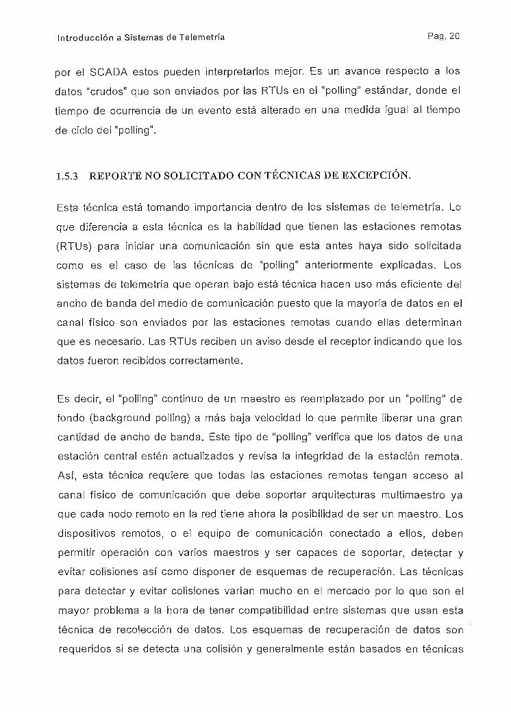
1.5.3 REPORTE NO SOLICITADO CON TÉCNICAS DE EXCEPCIÓN.
Esta técnica está tomando importancia dentro de los sistemas de telemetría. Lo
que diferencia a esta técnica es la habilidad que tienen las estaciones remotas
(RTUs) para iniciar una comunicación sin que esta antes haya sido solicitada
como es el caso de las técnicas de "polling" anteriormente explicadas. Los
sistemas de telemetría que operan bajo está técnica hacen uso más eficiente del
ancho de banda del medio de comunicación puesto que la mayoría de datos en el
canal físico son enviados por las estaciones remotas cuando ellas determinan
que es necesario. Las RTUs reciben un aviso desde el receptor indicando que los
datos fueron recibidos correctamente.
Es decir, el "polling" continuo de un maestro es reemplazado por un "polling" de
fondo (background polling) a más baja velocidad lo que permite liberar una gran
cantidad de ancho de banda. Este tipo de "polling" verifica que los datos de una
estación central estén actualizados y revisa la integridad de la estación remota.
Así, esta técnica requiere que todas las estaciones remotas tengan acceso al
canal físico de comunicación que debe soportar arquitecturas multimaestro ya
que cada nodo remoto en la red tiene ahora la posibilidad de ser un maestro. Los
dispositivos remotos, o el equipo de comunicación conectado a ellos, deben
permitir operación con varios maestros y ser capaces de soportar, detectar y
evitar colisiones así como disponer de esquemas de recuperación. Las técnicas
para detectar y evitar colisiones varían mucho en el mercado por lo que son el
mayor problema a la hora de tener compatibilidad entre sistemas que usan esta
técnica de recolección de datos. Los esquemas de recuperación de datos son
requeridos si se detecta una colisión y generalmente están basados en técnicas

Introducción a Sistemas de Telemetría Pap. 21
de múltiples intentos de transmisión. Para la retransmisión de los datos, estos se
integran con técnicas para evitar colisiones como introducir mecanismos de
retardo aleatorio.
La técnica de reporte no solicitado por excepción requiere un medio físico de
comunicación mucho más flexible y un manejo de la comunicación más complejo.
Están hechas para la tecnología de comunicación "peer - to - peer". De forma
similar a la técnica de "polling" con técnicas de excepción, esta debe ser capaz de
diferenciar entre datos estáticos y eventos, proveyendo facilidades para etiquetar
con tiempo a los eventos.
1.6 TELEMETRÍA Y TELEMANDO
El uso de sistemas de
telemetría para control remoto
se ha ido incrementando en la
mayoría de industrias. Sin
embargo algunas industrias
han estado haciendo activo uso
de la telemetría y telecontrol
por muchos años y con
diferentes grados de
complejidad: la industria del agua, del petróleo y del gas. Uno de los dispositivos
más usados para control automático es el PLC (Programable Logic Controller).
Para integrar sistemas automáticos a un sistema de telemetría se ha entrelazado
PLCs y RTUs de variadas formas incluyendo el cableado de E/S. Pero es la
facilidad con que los PLCs han permitido el acceso de los datos de comunicación
a sus datos internos lo que a permitido que los sistemas de telemetría combinen
la fuerza de los PLCs para el control con la flexibilidad de las RTUs para la
comunicación.
La implementación de algunos sistemas enfocan al uso de PLCs como el

Introducción a Sistemas de Telemetría Pap. 22
dispositivo primario de datos de comunicación en arquitecturas remotas. Esta
aproximación debe ser mirada con cautela ya que la mayoría de PLCs son
diseñados para comunicaciones en LAN dentro de la planta industrial: muy pocos
PLCs disponen de los servicios requeridos en comunicación para un sistema de
telemetría. Algunos de esos servicios requeridos son el control de la eficiencia y
disponibilidad del dispositivo de comunicación tales como modems, radios, etc. El
uso de RTUs conectados a PLCs es la forma más eficiente de conectar sistemas
automatizados ya existentes a sistemas de telemetría (Fig.1.5). Actualmente, la
distinción entre RTUs y PLCs es cada vez más difusa, no porque los "PLCs estén
asemejándose a RTUs sino porque estas últimas han aumentado sus habilidades
para realizar funciones avanzadas de control.
Muchas RTUs, en la actualidad, tienen la capacidad de actuar como PLCs y una
variedad de técnicas de realizar control con RTUs están emergiendo. Por
ejemplo, la más interesante de estas y la que más promete a los usuarios de
sistemas de control es la que se relaciona con los nuevos estándares IEC de
programación abierta para PLCs. Dichos estándares, mientras ayudan a los PLCs
en la industria, están siendo tomados como estándares de programación de
RTUs.
La norma IEC1131-3 da cinco lenguajes de control y secuencia:
• SFC - Funciones secuenciales
• FB- Bloques de funciones
• LD- Diagramas de escaleras
• ST- Texto estructurado
• IL- Lista de instrucciones
Contrario a los lenguajes de programación propietarios (de cada marca), el
estándar IEC1131-3 ofrece la posibilidad de que las RTUs tengan compatibilidad
con los estándares internacionales para PLCs. Para aplicaciones de rango
pequeño y mediano, este estándar da a las RTUs la fuerza de los PLCs para
realizar tareas de control y por lo tanto, no es necesario tener simultáneamente

Introducción a Sistemas de Telemetría Pap. 23
un PLC y una RTU. Esto por supuesto redunda en un menor costo, reduce los
costos de entrenamiento de personal y facilita el mantenimiento, permitiendo
resolver problemas con más facilidad.
1.7 PROTOCOLOS
Un protocolo de comunicación es la descripción del formato de los datos que es
usado entre dos o más dispositivos los cuales envían mensajes de datos entre
sí1. Así, un dispositivo entiende el contenido del mensaje enviado por otro y lo
interpreta correctamente. Existe una gran cantidad de protocolos que son usados
mundialmente y que son especializados para ia aplicación para la cual fueron
desarrollados (protocolos propietarios).
Al igual que otros protocolos de comunicación, los de telemetría tienen una
amplia difusión en la industria. Su complejidad varía dramáticamente desde uno
muy simple para dos dispositivos que intercambian datos hasta aquellos que
soportan comunicación entre decenas de miles de ellos. Protocolos muy simples
no soportan algunos servicios y por lo tanto no se pueden aplicar exitosamente
en aplicaciones muy particulares.
Los servicios típicos que debe prestar un buen protocolo son:
• Interface de enlace de datos al canal físico de comunicación
• Direcccionamiento de la fuente y del destino
• Protección contra error
. División de grandes paquetes de datos para la transmisión
• Reestructuración de grandes paquetes de datos al ser recibidos
. Esquemas de recuperación
• Envío (routing) de datos a través de redes
• Diferenciación de datos: datos estáticos, eventos, eventos etiquetados en
tiempo, objetos, etc.
• Operaciones con datos: lectura, escritura, etc.
• Determinar la secuencia para la transmisión y recepción de datos

Introducción a Sistemas de Telemetría Pag. 24
Generalmente los protocolos se clasifican en propietarios y de dominio público.
Los primeros usualmente son desarrollados por una marca particular de
"hardware" (p.e. Siemens) y en raras ocasiones pueden comunicarse con redes
de telemetría de otros fabricantes. Los segundos se basan en estándares
internacionales (p.e. MODBUS, PROF1BUS, etc.) y dan la posibilidad de
comunicación con equipos de otras marcas.
COMENTARIOS SOBRE EL PROCESO DE ESTANDARIZACIÓN DEPROTOCOLOS.
Los estándares industriales e internacionales están cada vez teniendo mayor
impacto en los sistemas de telemetría, donde hasta poco tiempo atrás se tenían
exclusivamente protocolos propietarios.
La tendencia actual es tener arquitecturas abiertas dando así la posibilidad de
utilizar equipos de varios fabricantes.
El éxito de los protocolos estándares es que intentan ser, al menos en algunos
aspectos, "de cualquiera para cualquiera". Esto naturalmente hace que sean
eficientes en algunas aplicaciones y en otras no. El precio es que se puede
requerir mayor ancho de banda, o reducido número de estaciones o el mismo
canal; sin embargo estas pérdidas potenciales son compensadas por el uso de un
lenguaje común.
Las ventajas en SCADA y sistemas de telemetría son al momento de expandir,
modificar o alargar el tiempo de vida útil de ellos. Así se puede conectar equipos
de otros fabricantes para expandirse o modificar; y un protocolo estándar reduce
la necesidad de costosas y complejas "cajas negras" (gateways) para traducir los
protocolos. Estas cajas pueden ser lo más difícii de mantener en un sistema.
El soporte técnico es más accesible para sistemas estándar y la información

Introducción a Sistemas de Telemetría Pap. 25
disponible de los protocolos estándar permite que la gente de mantenimiento
tenga una mejor comprensión de su sistema y por lo tanto, encuentre y arregle las
fallas más rápidamente. El entrenamiento del personal es más barato y se
requiere un menor "stock" de repuestos.12
REFERENCIAS:i Telemetry Systems, Techniques and Standards
Philip Aubin, Junio 1997, Institute of Instrumentation and Control Australia Inc.Crude Oil and Product Pipelines: Petroneí, South ÁfricaIndustrial Projects and Technical Service -ATD OG 2, 1997, Siemens AG.

CAPITULO 2
SINAUT: SISTEMAS DE TELEMETRÍA SIEMENS
2.1 BREVE REVISIÓN DEL SISTEMA.
En el capítulo anterior se vio las tendencias y necesidades en sistemas de
telemetría de las diferentes áreas de la industria. El sistema de telemetría de
Siemens es uno de los pocos sistemas en el mundo que ofrece la mayor cantidad
de posibilidades de telecontro!, telemetría y tareas de control local en un solo
sistema. El sistema SINAUT ST1 está basado en la probada tecnología de PLCs
SIMATIC S5, también de Siemens. Mediante "hardware" y "software"
especialmente desarrollado se expanden los PLCs adicionándoles todas las
funciones de RTUs. Así se obtiene lo mejor de los sistemas en una sola unidad.
2.1.1 CARACTERÍSTICAS GENERALES DEL SISTEMA.
Este sistema de telemetría está diseñado para formar sistemas de automatización
distribuidos así como centralizados. Se disponen de diferentes tipos de unidades
de control con específicos rangos de funcionamiento que permiten cualquier
aplicación. Se pueden formar redes completas de control con estaciones locales
(RTUs), estaciones nodos y estaciones maestras. La información puede ser
intercambiada a larga distancia por enlaces privados (cable, FO), de radio o de
líneas públicas; por lo que dispondremos facilidades para establecer redes de
área amplia (WAN). Dado que Simatic S5 tiene acceso a redes locales (LAN)
como Profibus y Ethernet también se pueden construir complejos sistemas de
control local.
La unidad remota (RTU) está basada en el sistema de PLCs por lo que posee
todas las facilidades concernientes a fuentes de poder, procesadores para
diferentes tareas (incluyendo la comunicación), periferia de entrada/salida y

SINAUT: Sistemas de Telemetría SIEMENS Pag. 27
funciones de programación. Las unidades de periferia que están relacionadas
directamente con el proceso son fácilmente expansibles por medio de módulos
de entradas/salidas y de bus de datos. Se le ha añadido procesadores especiales
(TIMs) y módems para la ejecución de las necesarias funciones de
comunicación.
Dado que está basado en PLCs, se pueden llevar a cabo con mucha facilidad
tareas de control con funciones desarrolladas para Lazo Cerrado, Lazo Abierto y
Telecontrol. Adicionalmente, también se pueden colgar en cada RTU dispositivos
de monitorización local como paneles de operador, terminales HMI (Human
Machine Interface), impresoras y consolas.
El sistema de telemetría SINAUT ST1 dispone de las siguientes unidades:
. SINAUT ST100:
Este dispositivo está diseñado para el rango bajo de aplicaciones, principalmente
para uso como una "pura" RTU que dispone de ciertas facilidades de control
como el procesamiento de rutinas de teíecontrol y un rango restringido de tareas
de control. También puede actuar como Maestro para aplicaciones sencillas de
telecontrol.
. SINAUT ST115:
Dependiendo del procesador central, este dispositivo está diseñado para el rango
bajo y medio de aplicaciones; siendo más que una "simple" RTU una estación de
telecontrol para el manejo de procesos. También puede actuar como Maestro de
telecontrol o de nodo.
. SÍNAUTST135:
Esta unidad se constituye también en una estación de telecontrol y está diseñada
para un rango medio de aplicaciones, pudiendo realizar tareas mucho más
extensas de telecontrol, control en lazo abierto y cerrado. También puede actuar
como Maestro de telecontrol o de nodo.

SINAUT: Sistemas de Telemetría SIEMENS Pag. 28
. SINAUT ST155:
Esta estación de telecontrol cubre el rango alto de aplicaciones y puede realizar
tareas complicadas de telecontrol y control en lazo abierto y cerrado. Puede
también operar como un Maestro de telecontrol y de nodo de "alta capacidad"
para grandes redes de telemetría con alto flujo de datos.
Han sido utilizadas con éxito en aplicaciones como:
- Redes de aguas servidas
_ Tratamiento de aguas servidas
_ Monitorización y telecontrol de equipo de bombeo
- Transporte de petróleo y derivados por ductos
- Monitorización y telecontrol de instalaciones de energía alternativa (solar y de
viento)
- Monitorización y telecontrol de tráfico y de instalaciones de telecomunicaciones
- Monitorización y control de sistemas eléctricos de distribución.
En las tablas 2.1 y 2.2 se puede ver las posibilidades y alcances de estas
unidades.
2.1.2 ESTACIÓN DE TELECONTROL SINAUT ST100.
Se estudiará este dispositivo, puesto que como se verá posteriormente, formará
parte del sistema diseñado.
Como ya dijimos anteriormente, esta unidad se utiliza en aplicaciones de rango
bajo y como una RTU con algunas posibilidades de control y telecontrol. Consiste
esencialmente de los siguientes componentes:
. Procesador central CPU 103
» Módulos de bus
- Módulos (tarjetas) de entradas/salidas. Cada módulo de bus acepta dos

S1NAUT: Sistemas de Telemetría SIEMENS Pag. 29
módulos de E/S.
Módem.
TAB.2.1 Máxima periferia de SINAUT ST1
Entradasdigitales
DIEntradasdigitalesparaconteoSalidasdigitales
DOEntradasanálogas
AlSalidasanálogas
AOTIM V CP
ST100
CPU10256
4
56
12
6
1
CPU103136
8
136
28
14
1
ST115
CPU941128
8
128
32
32
1
CPU942256
8
256
48
48
6
CPU943512
16
512
64
64
6
CPU944
1024
128
1024
64
64
9
ST135
CPU922
1024
32
1024
192
192
8
CPU928B
1024
128
1024
192
192
15
ST155
CPU946
1024
128
1024
192
192
15
CPU947
1024
128
1024
192
192
15
TAB.2.2 Máximas velocidades de SINAUT ST1
Tiempo deejecución paraprograma de
telemetríaTiempo de
ejecución para1000 instrucciones
Memoria dePrograma
Memoria de datos
ST100
CPU102
30 ms
~
total:
4KB
CPU103
30 ms
10 ms
total:
20KB
ST115
CPU941
30 ms
15 ms
16KB
2KB
CPU942
30 ms
15 ms
32KB
10KB
CPU943
30 ms
10 ms
Total:
48KB
CPU944
10 ms
3 ms
total:
96KB
ST135
CPU922
28 ms
23 ms
64KB
22KB
CPU928B8 ms
1 ms
64KB
40KB
ST155
CPU9468 ms
1 ms
64KB
40KB
CPU947
8 ms
1 ms
64KB
40KB
Memoria requerida para el programa de telemetríaMemoria dePrograma
Memoria de datos
total:
4KB
11.7KB
1KB
11KB
1.25KB
12.1KB
1.3KB
Tanto los módulos de bus como la CPU son enganchados en una riel estándar
DIN de 35mm. Los módulos de bus junto con la periferia pueden ser distribuidos

SINAUT: Sistemas de Telemetría SIEMENS Pap. 30
hasta en cuatro filas (fig. 2.1). La tarjeta CPU 103 contiene el procesador central
para la ejecución del programa de telecontrol, del programa del usuario y la
fuente de poder con alimentación de 24VDC. Para que la unidad opere a
115/230VAC 60 Hz., se debe añadir un módulo de fuente AC. Los módulos de
periferia incluyen los siguientes:
• Módulos de Entradas y Módulos de Salidas Digitales con 4 y 8 canales.
• Módulos de Entradas y Salidas combinadas con 16 entradas (DI) y 16 salidas
(DO)
• Módulos de Entradas Analógicas (Al) con 4 entradas y Módulos de Salidas
Analógicas (AO) con 2 salidas
• Módulo Digital de Conteo Rápido 385B de un canal
• Módulo de control en lazo cerrado IP 262 y Módulo de control de Motor de
Pasos IP267
• Módulo de interface de telecontrol T1M011B.
« Módulo de interface serial CP521
Los módems no ocupan espacio en los módulos de bus y se enganchan
directamente en la riel DIN.
Fig.2.1
Teóricamente, hasta 16 módulos se
pueden conectar a la CPU 103
dando como resultado un máximo de
32 módulos-de E/S. Sin embargo,
esta configuración total depende de
ciertas condiciones. En la práctica, 9
módulos de bus deben ser
considerados como máximo o 18
puestos para módulos de E/S. Los
módulos digitales de 4 y 8 canales
pueden ser enchufados sin
restricción, para todos los otros incluyendo la interface de telecontrol TIM011B
únicamente se los puede enchufar en los primeros 8 puestos. Como el TIM
Fila No 4
Fila No 3
Fila No 2
Fila No 1

SINAUT: Sistemas de Telemetría SIEMENS Pag. 31
siempre está presente ya que es el que maneja la comunicación de telemetría
entonces quedan disponibles únicamente 17 puestos, lo que fija la capacidad de
esta estación remota a lo indicado en la tabla 2.11.
La interface de telecontrol T1M011B es utilizada para la transmisión de datos.
Esta trasmite y recibe datos de acuerdo con el protocolo SINAUT ST y dispone de
los siguientes modos o técnicas de recopilación de datos:
- Polling
- Espontáneo (técnica de excepción)
_ Cíclico
Las siguientes tecnologías de comunicación se pueden utilizar:
_ Líneas privadas: dedicadas
_ Líneas públicas: dial up
- Radioenlace
- Fibra Óptica
Únicamente se puede poner un TIM por estación ST100. Para mayor información
remitirse a los manuales de Siemens del equipo SINAUT y de los PLCs SIMATIC
S5.
2.1.3 ESTACIÓN DE TELECONTROL SINAUT ST115.
Esta estación remota puede realizar tareas de bajo y alto rango dependiendo del
tipo de procesador central utilizado. También se estudiará esta estación de
telecontrol puesto que este modelo será utilizado en el diseño del sistema.
Adicionalmente, puede realizar tareas de control de lazo cerrado y abierto de
rango bajo y medio.
Este dispositivo comprende una unidad básica y si se requiere unidades de
expansión. La unidad básica siempre incluye su propia fuente de poder y el

SINAUT: Sistemas de Telemetría SIEMENS Pag. 32
procesador central; mientras que las unidades de expansión pueden o no tener
fuente. Existen cuatro modelos de procesadores centrales que van desde una
CPU de bajo costo, la 941: 941, 942, 943 y 944. Cada procesador tiene una RAM
interna para el programa del usuario y los datos, la cual puede ser expandida por
cartuchos de memoria RAM o EPROM.
En las tablas 2.1 y 2.2 se puede ver las máximas capacidades de este equipo.
Tareas de automatización pueden ser implementadas mediante el uso de tarjetas
de periferia "inteligentes". Estas tarjetas, que se insertan en los bastidores o
unidades básicas, funcionan independientemente del procesador central y por lo
tanto sin cargarla. Tareas como control de válvulas, de temperatura, de humedad,
de velocidad, etc. son realizadas por esta periferia inteligente.
Para funciones de control en "lazo cerrado" las CPUs a partir de la 942 disponen
de un algoritmo PID integrado en su sistema operativo el cual sirve para
aplicaciones de control que no son críticas en tiempo. Así se pueden programar
hasta 8 lazos de control en el programa de usuario.
La ¡nterface de telecontrol, que es un módulo que se inserta en la unidad básica,
es el T1M11 que se encarga de recibir y trasmitir datos de acuerdo al protocolo de
SINAUT ST en los siguientes modos o técnicas de recopilación de datos:
- Polling
- Espontáneo (técnica de excepción)
- Cíclico
Las siguientes tecnologías de comunicación se pueden utilizar:
_ Líneas privadas: dedicadas
- Líneas públicas: dial up
- Radioenlace
_ Fibra Óptica
Si la estación de telecontrol ST115 está equipada con un procesador 941 solo
SINAUT: Sistemas de Telemetría SIEMENS Pag. 33
una ¡nterface TIM11 se podrá utilizar, sin embargo con las CPU 942 y 943 se
pueden utilizar hasta 6 TIM11 y con la 944 hasta 9.
Varias tarjetas de comunicación o procesadores de comunicaciones (CP) pueden
ser utilizados en esta estación:
- CP524 y CP525 para comunicaciones punto a punto
_ CP530, CP5430 y CP535 para comunicación en redes locales (LAN)
_ CP523, CP524 y CP525 para conectarse a dispositivos inteligentes como
impresoras, paneles de operador, etc.
_ CP526, CP527 y CP528 para enviar imágenes a monitores a colores.
Para mayor información remitirse a los manuales de Siemens del equipo SINALJT
y de los PLCs SIMATIC S5.
CPU
FIG. 2.2
T
M
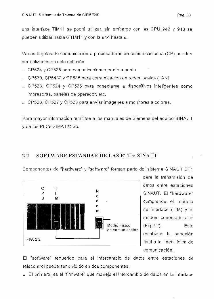
2.2 SOFTWARE ESTÁNDAR DE LAS RTUs: SINAUT
Componentes de "hardware" y "software" forman parte del sistema SINAUT ST1
para la transmisión de
datos entre estaciones
SINAUT. El "hardware"
comprende el módulo
de interface (TIM) y el
módem conectado a él
(Fig.2.2). Este
establece la conexión
final a la línea física de
comunicación.
E! "software" requerido para el intercambio de datos entre estaciones de
telecontrol puede ser dividido en dos componentes:
• El primero, es el "firmware" que maneja el intercambio de datos en la interface
Medio Físicode comunicación

SINAUT: Sistemas de Telemetría SIEMENS Pap. 34
de telecontrol TIM de acuerdo al protocolo SINAUT ST. Este es suministrado
en la forma de un cartucho de memoria EPROM que se inserta en las unidades
TIM.
• El segundo componente es un paquete de "software" llamado SINAUT TD1 el
cual es el responsable por la compilación de los mensajes transmitidos y la
evaluación de aquellos recibidos en las estaciones de telecontrol SINAUT ST1
a través de las interfaces TIM. Este es cargado en el procesador central o CPU
y es ejecutado en un ciclo de programa.
2.2.1 PROCESAMIENTO DE DATOS EN LA ESTACIÓN DE TELECONTROL
El flujo de datos en una estación de telecontrol SINAUT ST1 se puede observar
en el diagrama esquemático de la figura 2.3. El estado de las señales discretas es
tomado por las tarjetas digitales y los valores de mediciones por las tarjetas
analógicas de entrada. Los comandos del sistema se entregan al proceso por
salidas digitales y las consignas por medio de las salidas analógicas2.
El programa que procesa los datos entrantes y los salientes está constituido por
un componente creado por el usuario (programa de usuario) y por otro para el
telecontrol. El programa del usuario incluye las tareas de control en lazo abierto y
cerrado que son programadas usando el lenguaje de programación de los PLCs
SIMATIC S5, el STEP5 y sus diferentes presentaciones (escalera, bloques de
funciones e instrucciones).
Los datos adquiridos vfa ¡as tarjetas de entrada o ya procesados por el programa
de! usuario son compilados por el programa de telecontrol en mensajes que
luego son transmitidos hacia un maestro. En la otra dirección, el programa de
telecontrol evalúa el mensaje recibido del maestro, pasa los comandos y
consignas hacia el programa del usuario para ser procesados o directamente a
las tarjetas de salida.

Flu
jo d
e da
tos
en u
na E
stac
ión
de T
elec
ontr
ol
Pro
ceso
Tar
jeta
s de
E/S
Pro
cesa
dor
Cen
tral
CP
UM
ódul
o JI
ME
quip
o d
e T
ransm
isió
nT
ecno
logí
a de
Com
unic
ació
n
Mem
oria
dem
ensa
jes
atransm
itir
SIN
AU
T:
Sis
tem
a de
Tel
emet
ría
de S
iem
ens
Fig
. 2.3

SINAUT: Sistemas de Telemetría SIEMENS Pag. 36
El sistema de telecontrol SINAUT ST1 tiene un paquete de software constituido
de subrutinas (Función Blocks FB) con los cuales se forma el programa de
telecontrol. Esas subrutinas simplemente deben ser instaladas en el orden
correcto dentro de la CPU de la estación y fijados sus parámetros para construir
el programa de telecontrol adecuado para la aplicación. Este paquete se conoce
como SINAUT TD1 y básicamente tiene rutinas que compilan los mensajes a ser
transmitidos y evalúan los recibidos. También contiene subrutinas con funciones
auxiliares o de arranque.
Las subrutinas para la compilación de mensajes revisan constantemente los
datos recibidos de los módulos de entrada buscando cambios puesto que
únicamente los datos que cambian son transmitidos. Asignando valores a los
parámetros de las subrutinas, el usuario puede decidir cuales datos se
trasmiten y cuales cambios disparan la transmisión.
Los datos a transmitir son almacenados en forma de mensajes en una memoria
especial. Luego que todos los mensajes a transmitir son compilados, son
transferidos a la interface de telecontrol TIM los cuales son nuevamente
almacenados en su propia memoria. Esta transferencia es llevada a cabo por una
subrutina auxiliar que es parte del paquete TD1.
El firmware (cartucho EEPROM del TIM) "trasmit messages" en la interface de
telecontrol convierte los mensajes de acuerdo con el protocolo de transmisión y
los trasmite por medio del dispositivo de comunicación hacia el maestro en la
forma predefinida y con la velocidad escogida. Los parámetros de transmisión
tales como tipo de red, modo de operación, velocidad, factor de repetición, etc.
son transferidos al TIM por la CPU en el arranque del equipo por medio de una
subrutina que es parte del paquete TD1.
El firmware "recive messages" en el TIM decodifica el mensaje recibido del
maestro de acuerdo al protocolo SINAUT ST, busca errores de transmisión y
compara el número de estación contenido en el mensaje con el de su propia

SINAUT: Sistemas de Telemetría SIEMENS Paq. 37
estación. Solamente los mensajes libres de errores y enviados para una estación
en particular son almacenados en la memoria de recepción de mensajes del T1M.
El contenido de esta memoria es leído periódicamente por la CPU de la estación
por medio de otra subrutina contenida en el paquete TD1. Los mensajes recibidos
son procesados en el orden en que han sido almacenados en la memoria de
recepción de mensajes y por las subrutinas responsables por la evaluación de los
mismos. Dependiendo de los parámetros asignados a esas subrutinas, la
información de los mensajes será enviada directamente a las salidas o puestas a
disposición del programa del usuario para un posterior procesamiento.
Si una estación SINAUT ST1 es usada como maestro, usualmente se tienen
varios TIMs operando simultáneamente por lo que el programa de telecontrol se
lo debe adaptar para que pueda operar con ellos.
Para diferenciar el software de las estaciones de telecontrol, el paquete SINAUT
TD1 se divide en cuatro subpaquetes:
. SINAUT TD100 para la estación ST100
. SINAUT TD115 para la estación ST 115
. SINAUT TD135 para la estación ST 135
. S1NAUTTD155 para la estación ST 155
2.3 TIM: MÓDULOS DE INTERFACE DE TELECONTROL
Los módulos de telecontro! TIM, son tarjetas inteligentes basadas en
microprocesador, las cuales manejan independientemente todas las funciones de
transmisión de datos. Existen dos modelos: TIM 11 y TIM 011B.
2.3.1 TIM 11
Esta tarjeta es usada en las estaciones ST115, ST135 y ST155. Para que se

SINAUT: Sistemas de Telemetría SIEMENS Pap. 38
pueda adaptara una amplia variedad de módems, existen varios tipos de pórticos
intercambiables, los cuales son enchufables en un zócalo en la parte frontal de la
tarjeta. Estos pórticos son:
. V.24 (RS232) longitud máxima 15m.
• X.21 longitud máxima 15 m.
. TTY (RS485) longitud máxima hasta 1000m.
Usualmente se utiliza el pórtico V.24 porque la mayoría de módems disponen de
esta interface. El pórtico TTY se utiliza para módems fabricados por Siemens.
Adicionalmente, en otro zócalo, el TIM 11 tiene un cartucho de memoria e! cual
contiene 32KB de RAM y 8, 16 o 32KB de EPROM. La memoria EPROM contiene
parte del "firmware" que determina el protocolo para la transmisión de datos. Otra
EPROM ubicada en el interior del TIM 11 contiene el resto del "firmware" y el
sistema operativo del TIM. Los 32KB de RAM son utilizados para almacenar los
mensajes a trasmitir o recibir y los números telefónicos necesarios cuando la
estación opera en líneas telefónicas.
2.3.2 TIM011B
Este es utilizado para estaciones SINAUT ST100. Este módulo tiene una interface
fija V.24 (RS232). En un cartucho de memoria que se introduce en un zócalo de
la tarjeta se tiene 32KB de EPROM con el "firmware" del TIM y 64KB de RAM.
Aproximadamente 12KB de esta RAM es utilizada por el TIM para operaciones
internas y los 52KB para almacenar mensajes para transmitir o recibir y números
para las llamadas cuando la estación opera en redes telefónicas.
2.3.3 LOS TIMS Y LAS TECNOLOGÍAS DE COMUNICACIÓN
Los módulos de telecontrol TIM manejan el intercambio de datos de acuerdo al
protocolo SINAUT ST. Debido al amplio rango de posibilidades de este protocolo,

SINAUT: Sistemas de Telemetría SIEMENS Pag. 39
fue necesario dar a los TIMs posibilidades de trabajar con cuatro tecnologías de
comunicación con un "firmware" para cada una:
• Para transmisión en líneas dedicadas (privadas)
. Para transmisión en líneas públicas
• Para Fibra Óptica
• Para Radioenlace
Así mismo los módulos TIMs pueden transmitir y recibir en los siguientes modos o
técnicas de recolección de datos:
• Polling
• Espontáneo sin marcado
. Espontáneo con marcado
• Cíclico con "acuse recibo"
• Cíclico sin "acuse recibo"
2.3.4 DATOS ADICIONALES SOBRE LOS TIMS
Los módulos TIMs pueden funcionar como estaciones esclavas o maestras, pero
el TIM 11 adicionalmente como estación nodo (ver Fig. 2.4). El TIM se configura
con cualquiera de las funciones anteriores cuando recibe los parámetros de
inicialización en el arranque.
Cuando un módulo TIM esta instalado en una estación esclavo, entonces maneja
el intercambio de datos con el maestro y con las estaciones nodo. Una estación
maestra puede tener instaladas varios módulos TIM configurados como maestros
y que serán los responsables del intercambio de datos con los esclavos y las
estaciones nodo. Una estación nodo funciona de manera similar a una estación
esclava pero con la diferencia que a través de él son intercambiados los datos
entre el maestro y algunas estaciones esclavas (Fig.2.4)
El número de mensajes que puede enviar una estación está determinada, por un

SINAUT: Sistemas de Telemetría SIEMENS Pap. 40
lado, por la capacidad de la memoria de mensajes del TIM y por el tamaño del
mensaje. Sin embargo, la capacidad del procesador central de cada estación
SINAUT ST1 deberá tomarse en cuenta puesto que una considerable parte de las
tareas de compilación de mensajes y evaluación de mensajes transmitidos y
recibidos son realizadas en él. Un máximo de 250 mensajes de telecontrol o de
telemetría2.
El número de TIMs configurados
como maestros que se pueden
instalar en una estación maestra
o de nodo ST1 depende del tipo
de procesador central y del
modelo de estación que se
tenga. Así la estación ST155, la
más poderosa, maneja un
máximo de 15 TIMs mientras
que la ST100 puede únicamente
manejar un TIM.
Maestro
TIM M TIM M
TIM N
Nodo
TIM M TIM M
FIG. 2.4
La velocidad de transmisión en un TIM puede fijarse desde O a 9600 bps. Sin
embargo el TIM 011B tiene una máxima velocidad de transmisión de 2400 bps1.
2.4 PROTOCOLO SINAUT ST
El sistema de telemetría y telecontrol SINAUT ST1 usa para transmitir datos por
el medio físico, el protocolo SINAUT ST. Este protocolo está basado en la norma
IEC 870. El protocolo SINAUT ST define no solamente la estructura del mensaje
sino también los parámetros que definen como se realiza el intercambio de datos.
Este protocolo se encuentra instalado en los módulos TIMs en forma de software.
En la CPU de la estación, el paquete de software TD1 provee el soporte
necesario a los módulos de interface de telecontrol.

SINAUT: Sistemas de Telemetría SIEMENS Pací. 41
Los módulos TIM pueden transmitir y recibir datos en los siguientes modos o
técnicas de recolección de datos;
• Polling
• Cíclico
• Espontáneo
2.4.1 MODO DE POLLING
En este modo de transmisión, como vimos en el Capítulo I, el intercambio de
datos es controlado por un maestro. Este llama a las estaciones esclavas o nodos
que se encuentran conectadas a la red en forma ordenada y en turnos. Las
estaciones con datos a ser transmitidos, los envían tan pronto ellas son
requeridas por el maestro. Las estaciones que no tienen datos para transmitir
simplemente responden con un "acuse recibo".
2.4.2 MODO CÍCLICO
Esta técnica es una variación de "reporte no solicitado con técnica de excepción"
(ver Capítulo I), En este modo el TIM maestro y la estación esclavo o de nodo
transmiten constantemente datos en ambas direcciones simultáneamente e
independientemente de cualquier otro. Existe una cierta dependencia recíproca
en el intercambio de datos cíclicos, porque.el TIM únicamente envía el siguientes
mensaje cuando recibe el "acuse recibo" respecto al último mensaje transmitido.
Sin embargo, existe una variación de este modo cíclico que trabaja sin "acuse
recibo".
2.4.3 MODO ESPONTÁNEO
Este modo es para intercambio de datos en redes telefónicas públicas. El TIM
SINAUT: Sistemas de Telemetría SIEMENS Pag. 42
debe tener un significativo cambio en sus datos antes de que estos sean
transmitidos espontáneamente. Por lo anteriormente expuesto, esta técnica
también es una variación de "reporte no solicitado con técnica de excepción" pero
para líneas telefónicas.
2.4.4 PROCESO DE COMPILACIÓN, TRANSMISIÓN Y RECEPCIÓN
El TIM compila los datos transferidos de la CPU (ver Fig. 2.3) a mensajes SINAUT
ST añadiendo los identificadores requeridos e incluyendo caracteres de revisión
dentro de los datos. Después de que un mensaje ha sido transmitido
exitosamente, este es borrado de la memoria de transmisión del TIM.
Todos los mensajes recibidos son revisados mediante la técnica del carácter de
revisión para comprobar si no están corruptos. También se evalúa la dirección de
la estación y la identificación del mensaje, luego de lo cual se procede a enviarlo
a la CPU para su posterior tratamiento. La estación que recibe confirma la
recepción libre de errores con un mensaje de "acuse recibo".
Un mensaje recibido que incluye una identificación de repetición, es pasado a la
CPU si el TIM aún no lo ha recibido y envía un "acuse recibo" a la estación que lo
envió. Si el mensaje ya fue recibido, simplemente se envía el mensaje de "acuse
recibo" y no se lo pasa a la CPU. Esto evita la duplicación innecesaria de
mensajes tanto en la estación remota como en el maestro.
2.4.5 TIPOS DE DATOS
En el Sistema SINAUT, la información a ser transmitida es clasificada en
diferentes tipos de datos:
• Señales de estado
Es una alarma (p.e. límites excedidos) o señal de proceso (p.e. encendido de

SINAUT: Sistemas de Telemetría SIEMENS Pag. 43
bombas, apertura de válvulas). Consiste de información binaria con valores O o 1,
8 señales de estado son compiladas dentro de un byte2.
* Valor análogo
Es un valor analógico de proceso tal como presión, temperatura, etc. Es adquirido
por una tarjeta analógica de entrada en forma de corriente o voltaje y convertida a
un valor codificado en binario. El valor así convertido ocupa una palabra: 12 bits +
uno de signo y 3 bits de código. Un valor analógico también puede ser entregado
por el programa de usuario en el formato ya indicado2.
. Comando
Es una información binaria que es transmitida una vez como 1 cuando una señal
cambia de O a 1, sin embargo un flanco negativo de 1 a O no dispara una
transmisión. En el dispositivo de recepción, un comando es una salida como
pulso en las tarjetas digitales de salida o es borrada por el programa del usuario
después de que ha sido ejecutado exitosamente. Ocho comandos son
compilados en un byte2.
* Consigna (set point)
Es un valor digital o analógico que es transmitido una vez después que el valor ha
sido fijado. Una consigna siempre requiere una Palabra (Word) formada por 12
bits con signo y 3 bits de valor O o cualquier patrón de 16 bits. En el dispositivo de
recepción, la consigna puede ser sacada directamente al proceso por las tarjetas
de salida analógicas o puesta a disposición del programa del usuario para su
posterior procesamiento2.
2.4.6 MENSAJES
Un mensaje es un conjunto de datos que se transmiten simultáneamente. Un
mensaje contiene solamente un tipo de datos. Por lo tanto, de la misma forma
que existen varios tipos de datos para transmitir existen diferentes tipos de

SINAUT: Sistemas de Telemetría SIEMENS Pag, 44
mensajes:
. Mensajes con señales de estado (16 o 32 señales de estado por mensaje)
• Mensajes de valores analógicos (4 o 8 valores analógicos por mensaje)
• Mensajes de comandos (8 comandos por mensaje)
• Mensajes de consignas (1 consigna por mensaje)
La cantidad total de datos a transmitir es dividida en un número apropiado de
mensajes. Cuando un mensaje está listo para ser transmitido desde una estación
remota o desde un nodo, el usuario puede especificar si un mensaje será
transmitido únicamente cuando su contenido cambie (mensaje espontáneo) o si
es transmitido continuamente (mensaje permanente). Los mensajes transmitidos
por un maestro siempre son enviados en modo espontáneo.
En el modo de "polling" y en el modo "cíclico", mensajes espontáneos y
permanentes pueden ser mezclados en estaciones remotas y estaciones nodos.
En el modo cíclico, al menos un mensaje debe ser permanente; en el modo de
polling, es posible operar sin un mensaje permanente y transmitir únicamente
mensajes espontáneos.
Cada mensaje que es transferido sin errores tiene su "acuse recibo" por parte de
la estación receptora. Mensajes que no tienen su "acuse recibo" son
automáticamente retransmitidos por el TIM que lo emitió. El número de veces que
se intenta la retransmisión puede ser fijado por el usuario. Si se completa el
número prefijado de veces que se intenta la retransmisión sin tener éxito,
entonces el TIM emite un mensaje de error hacia la CPU de la estación.
Por otro lado, la estación remota y la estación maestra responden en forma
diferente;
• Una estación remota continua intentando transmitir los mensajes que "no
tuvieron "acuse recibo". El mensaje siempre se mantiene en la memoria de
transmisión hasta que se logra el "acuse recibo".
• Una estación maestra borra el mensaje que no tiene "acuse recibo" , de su

SINAUT: Sistemas de Telemetría SIEMENS Pap. 45
memoria de transmisión luego de cumplido los intentos fijados. Si es necesario,
el T1M puede devolver el mensaje a la CPU de la estación.
También de acuerdo a la categoría del mensaje se pueden clasificar en:
• Mensajes de organización
Estos cumplen funciones para organizar el sistema de telemetría y telecontrol.
Estas funciones son: Solicitudes generales y específicas, sincronización de
relojes, coordinación para establecer y terminar la comunicación en redes
públicas, mensajes para el arranque y para reportar fallas.
• Mensajes solicitados
Son mensajes similares a los de datos, sin embargo estos contienen un
identificador especial que los diferencia. Estos mensajes son una respuesta a
los mensajes de organización.
2.4.6.1 Mensajes de solicitud general y específica
Utilizando una "solicitud general" (general request), el maestro puede actualizarse
a sí mismo: se solicita de todas las estaciones mensajes con información
actualizada1. La "solicitud" no es un modo (técnica) adicional sino que es una
función del sistema que se puede producir en los tres modos (polling, espontáneo
y cíclico).
Además de la "solicitud general" a todas las estaciones y la "solicitud general" a
una sola estación, existe también la "solicitud específica" (specific request) con lo
cual un mensaje específico es solicitado desde una estación remota. Todos estos
tipos de "solicitudes" pueden ser disparados en cualquier momento por el
programa del usuario.
También se pueden tener "solicitudes generales automáticas" (automatic general

S1NAUT: Sistemas de Telemetría SIEMENS Pag. 46
request) para todas las estaciones remotas cuando un maestro está ¡nicializado o
a una sola estación remota cuando la estación informa que está inicializándose o
cuando nuevamente está disponible luego de una falla. De la misma forma que
un maestro, una estación nodo puede, si es necesario, lanzar solicitudes a sus
estaciones.
Las solicitudes recibidas del maestro o de una estación nodo son manejadas por
el TIM de la estación direccionada. Para responder a la solicitud, usa su memoria
de mensajes que contiene la información más actualizada de todos los mensajes:
todos los mensajes son tomados de esta memoria, son marcados como
"solicitados" e inmediatamente entrados en la memoria de transmisión (ver
Fig.2.3).
Cuando existe una solicitud general, el TIM "no ingresa simultáneamente todos los
mensajes marcados como solicitados en la memoria de transmisión sino que
sigue el siguiente procedimiento; Primero, únicamente un número determinado de
mensajes (que es seleccionado por el usuario) son ingresados en la memoria de
transmisión. Siguiendo, cada vez que un mensaje es transmitido otro que está
marcado como "solicitado" es ingresado en la memoria de transmisión. De esta
manera, el TIM evita que información importante del proceso sea retrasada
demasiado en su transmisión cuando existe una "solicitud general" ya que envía
mezclado mensajes solicitados y de proceso.
2.4.7 MODO O TÉCNICA DE RECOLECCIÓN DE DATOS "POLLINO"
Dado que en el posterior diseño del sistema se escogerá este tipo de técnica, a
continuación se detallará como funciona.
En sistemas S1NAUT el modo de "polling" es únicamente utilizado en líneas
dedicadas. El módulo TIM de la estación maestra controla el ciclo del "polling"

SINAUT: Sistemas de Telemetría SIEMENS Pag. 47
(ver Fig. 2.5). Las estaciones remotas que serán contactadas dentro de ese ciclo
son registradas en una lista dentro del TIM del maestro. Esta lista es transferida al
T1M desde la CPU de la estación maestra durante el arranque de la misma. La
estación maestra solicita, por medio de los mensajes "Pn", a las estaciones
remotas el envío de sus datos. Para garantizar un ciclo de poiling (polling cycle)
corto, en operación normal cada estación remota transmite únicamente datos que
han cambiado. Si no hay datos que han cambiado, se tiene únicamente el
mensaje de "acuse recibo" A. El usuario puede decidir para cada mensaje,
dependiendo del tipo de información que lleve (p.e. señales de estado, valores
análogos, etc.), cuales cambios producirían una transmisión.
Una estación remota que ha sido contactada para enviar datos, adjunta un
identificador al último mensaje. Mientras este identificador no es recibido por la
estación maestra, la comunicación se mantendrá entre este maestro y la estación
remota. Para prevenir que un tiempo de ciclo sea bloqueado por una estación con
un continuo cambio de datos, el TIM de la estación remota marca el último
mensaje en su memoria de transmisión con el momento .del contacto desde el
maestro. Mensajes que son leídos luego de este momento son transmitidos en el
siguiente contacto desde el maestro.
Mensajes de control CMn/m con comandos o consignas o mensajes de
organización tales como "solicitud general o específica" pueden ser incluidos por
el maestro en cualquier momento en el ciclo de "polling". Son transmitidos
inmediatamente después de terminar un contacto con una estación remota el cual
está constituido por un mensaje de "polling" Pn y un mensaje de "acuse recibo" A
o un mensaje de "polling" Pn y un mensaje de datos Dn/m. Si varios mensajes de
organización o de control están simultáneamente esperando para ser
transmitidos, un número determinado de ellos pueden ser transmitidos uno
después de otro. El ciclo de "polling" será interrumpido por la duración de la
transmisión de estos mensajes. El número máximo de mensajes a ser
transmitidos entre contactos con el maestro, es determinado por parámetros
entregados por la CPU al TIM durante el arranque del equipo.

LJs
SIE
ME
NS
Dia
gram
a de
tiem
po
del
Mod
o de
Polli
ng
MD
P1P
2P
3C
3/1
P1! C
M3/
1P
2C
2/2
P3'
Áf
LE 3
/2 CM
2/2
P1
C3/
2
P21
1C
M3/
2P
2E
2/U
I
P3
f 1
C3
/1T
E3
/2I
D3/
2:
CD
MD
A
P1
A K3
M
P2E
2/2 1
D2/2
P3
D3/
1
P3*
E3
/1 A
I
D3/1
P1
A
Cl/
l
P2. ¡A
CM
1/1 i
Cl/í^
/\
.C
M1/
1*
A
t
CM
1/1*
A
P3
f^
CD
MD
Pn
A t
Dire
c. d
e co
ntro
l C
n/m
Dire
c. d
e m
onito
rizac
ión
CM
n/m
Men
saje
de
Pol
üng
En/
m
Men
sje
de a
cuce
reci
bo
Dn/
m
Tie
mpo
de
mon
itoriz
ació
n D
n/m
Info
rmac
ión
de c
ontr
ol
Men
saje
de
cont
rol
Eve
nto
en la
est
ació
n
Men
saje
de
dato
s
Mar
cado
com
o "u
ltim
o m
ensa
je"
n/m
SIN
AU
T:
Sis
tem
a de
Tel
emet
ría
de S
iem
ens
Mar
cado
com
o "r
epet
ido"
Tra
nsm
isió
n si
n er
ror
Tra
nsm
isió
n c
on e
rror
Est
ació
n/M
ensa
je
Fig
.2.5

SINAUT: Sistemas de Telemetría SIEMENS Pa.q. 49
2.4.7.1 Ciclo principal y secundario
El ciclo de "polling" en la estación maestra puede ser arreglado para colocar
ciertas estaciones en un "ciclo principal" y otras en un "ciclo secundario" (ver
Fig.2.6). Esta definición es realizada por medio de parámetros que son
transmitidos al TIM por la CPU en el arranque de la estación. El ciclo secundario
es siempre realizado luego del ciclo principal, es decir, luego que todas las
estaciones en el ciclo principal son contactadas.
C. Principal
C. Secundario
Fig. 2.6
2.4.7.2 Polling continuo
Una técnica de polling adicional es el contacto "continuo" a una estación remota.
El usuario puede cambiar o especificar, en cualquier momento, cual estación
remota va a ser contactada "continuamente". El contacto continuo con una
estación no interrumpe el ciclo de "polling" normal puesto que es realizado
alternativamente con los contactos normales (Fig. 2.7).
Fig, 2,7

SINAUT: Sistemas de Telemetría SIEMENS Paq. 50
2.4.7.3 Comportamiento cuando falla la comunicación
Si una estación remota no responde o si el mensaje recibido está dañado, el
maestro contactará nuevamente a la estación. Sin embargo, en esta ocasión el
mensaje de contacto "Pn" será marcado como "repetido" lo cual indica a la
estación remota que reenvíe el último mensaje. Así un mensaje "Pn" servirá como
un "acuse recibo" del maestro: un "Pn" con identificador de repetición indicará que
el mensaje no llegó correcto. Si una estación no responde a todos los intentos o
no se tiene éxito en transmitir un mensaje sin errores, seguirá siendo contactada
dentro del ciclo de polling con un mensaje marcado como "repetido" pero desde
ese momento por una sola vez. Únicamente cuando la estación empiece a
responder sin errores el factor de repetición regresará al valor original.
La estación remota repite el último mensaje (Fig. 2.5) hasta que reciba el "acuse
recibo" del maestro, es decir hasta que el mensaje [[Pn" no se encuentre marcado
como "repetido". Para vigilar la línea física de comunicación el T1M de la estación
remota revisa el número de repeticiones del mensaje; si este alcanza el máximo
factor de repetición especificado, un mensaje de error es enviado a la CPU de la
estación. Adicionalmente, el TIM vigila para determinar si existe algún intercambio
de datos y si es contactado por el maestro dentro de cierto lapso de -tiempo.
2.4.8 ESTRUCTURA DE LOS MENSAJES EN EL PROTOCOLO SINAUT ST
Los mensajes están formados por bytes empacados en un carácter asincrónico
de 11 bits (ver Fig.2.8) entre los cuales se encuentra un bit de inicio (siempre 0),
uno de parada (siempre 1) y otro de pandad. El mensaje de datos como su
CARÁCTER ASINCRÓNICO 1 1 BITS
U bits de datos mbit de bit de
l r
* inicio=0 pandad *bit de
Fig. 2.8 parada= 1

SINAUT: Sistemas de Telemetría SIEMENS Pap. 51
nombre lo indica es usado para transmitir información de procesos como señales
de estado, valores analógicos, comandos y consignas.
2.4.8.1 Estructura del mensaje de datos
El mensaje de datos está formado por un carácter definido de inicio y por otro de
parada. La información dentro del mensaje es de una longitud e información
variable y puede tener entre 1 y max.120 bytes de información. Adicionalmente,
se tiene un encabezado de mensaje de longitud fija. Este contiene la información
de la longitud del mensaje, el número de mensaje y el de estación, así como
también dos bytes identificadores (Fig. 2.9).
Cada byte de la estructura del mensaje está autoprotegido. contra errores con el
bit de paridad en el carácter asincrónico, mientras que la parte del mensaje que
es identificada por la longitud de bloque es también protegida.por una palabra de
control (checkword). Mientras que el carácter de inicio y la longitud de bloque que
no están protegidos por la palabra de control son transmitidos dos veces.
2.4.8.2 Estructura del mensaje de "polling"
Este tipo de mensaje es únicamente usado en el modo de polling (Pn) y tiene una
longitud fija de 5 bytes. Para que este mensaje sea reconocido como mensaje de
"polling" por la estación receptora, su carácter de inicio es diferente al de mensaje
de datos. El carácter de finalización es igual que el que se tiene en el mensaje de
datos.
2.4.8.3 Estructura del mensaje de "acuse recibo"
Este mensaje tiene una longitud fija de 1 byte y dependiendo de la dirección del
mensaje tiene un código hexadecimal E5 si va del esclavo al maestro y A2 deli
maestro al esclavo.
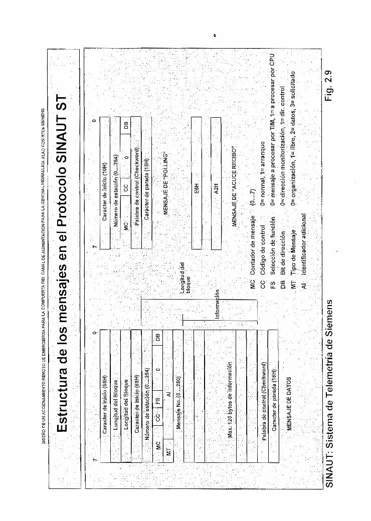
üs S
IEM
EN
S
Est
ruct
ura
de
los
men
saje
s en
el P
roto
colo
SIN
AU
T S
T
Car
ácte
r de
inic
io (
68H
)
Long
itud
del
Blo
que
Long
itud
del B
loqu
e
Car
ácte
r de
inic
io (
68H
)
Núm
ero
de e
stac
ión
(0...
.254
)
MC
CC
FS
O
MT
Al
Men
saje
No.
(0...
.250
)
Max
. 120
byt
es d
e in
form
ació
n
Pal
abra
de
cont
rol
(Che
ckw
ord)
Car
ácte
r de
par
ada
(16H
)
ME
NS
AJE
DE
DA
TOS
DB
Info
rma
Car
ácte
r de
inic
io (
10H
)
Núm
ero
de e
stac
ión
(0...
.254
)
MC
ce0
DB
Pal
abra
de
cont
rol (
Che
ckw
ord)
Car
ácte
r de
par
ada
(16H
)
ME
NS
AJE
DE
"PO
LLIN
O"
Long
itud
del
bloq
ue
E5H
:ion
A2H
ME
NS
AJE
DE
"AG
UC
E R
EC
IBO
"
MC
C
on
tad
or
de m
ensa
je
CC
C
ódig
o d
e c
ontr
ol
FS
Se
lecc
ión
de fu
nci
ón
DB
B
it de
dir
ecc
ión
MT
T
ipo
de
Men
saje
Al
Identífic
ádor
adic
ional
(0...
.7)
0= n
orm
al,
1= a
rra
nq
ue
0= m
ensa
je a
pro
cesa
r p
orT
IM,
1= a
pro
cesa
r por
CP
U
0= d
ire
cció
n m
onito
riza
ción,
1=
dir.
co
ntr
ol
0= o
rganiz
aci
ón,
1= li
bre
, 2=
dato
s, 3
= s
olic
itado
SIN
AU
T: S
iste
ma
de
Tel
emet
ría
de
Sie
men
sFi
g. 2
.9

S1NAUT: Sistemas de Telemetría SIEMENS Pag. 53
2.5 ESTRUCTURAS DE REDES
Existen varias opciones en estructuras de redes que revisaremos a continuación:
2.5.1 CONEXIÓN PUNTO A PUNTO
Esta es la red más simple. Un TIM maestro (TIM M) se comunica únicamente con
una estación remota (TIM E). La comunicación puede ser en 2 o 4 hilos. Para la
transmisión de datos se puede utilizar el modo de "polling" o el cíclico (ver Fig,
2.10). Esta conexión es posible en líneas dedicadas o privadas.
Fig. 2.1
M. a
estro
TIM
M
MODEM
D
MODEM
TIM
E
EscIaV
o
2.5.2 RED MULTIPUNTO
Se caracteriza por tener varias estaciones conectadas a lo largo de la línea de
transmisión. Las estaciones están conectadas a los mismos hilos y únicamente
un maestro maneja el intercambio de datos con todas las estaciones remotas. El
patrón de comunicaciones puede ser en 2 o 4 hilos.
En esta topología de redes los datos pueden ser intercambiados únicamente en
el modo de "polling". Varios tipos de modems se pueden utilizar pero estos deben
tener la posibilidad de conectarse en "derivación" o en paralelo a los hilos de
transmisión (ver Fig. 2.11). Esta conexión es posible en líneas dedicadas o
privadas.
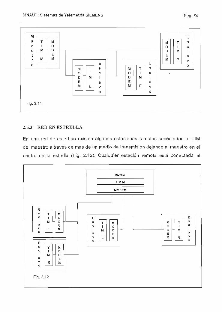
S1NAUT: Sistemas de Telemetría SIEMENS Pa.q. 54
Fig. 2.11
EscIavo
2.5.3 RED EN ESTRELLA
En una red de este tipo existen algunas estaciones remotas conectadas al TIM
del maestro a través de mas de un medio de transmisión dejando al maestro en el
centro de la estrella (Fig, 2.12). Cualquier estación remota está conectada al
Fig. 2.12
Maestro
TIM M
MODEM
EscIaV
o
TIM
E
-
MODEM
EscIaV
o
TiM
E
M0DEM
Es T
c I1 M ~~a
v E
M0DEM
-
T1
M
E
Esc
avo

SINAUT: Sistemas de Telemetría SIEMENS Pag. 55
maestro como una conexión punto a punto o algunas estaciones están
conectadas a lo largo de líneas de transmisión como en el caso de redes
multipunto. El intercambio de datos es posible únicamente en el modo de "polling"
y es posible en líneas dedicadas, en redes de radio y en FO.
2.5.4 REDES TELEFÓNICAS PUBLICAS
Aparte de la comunicación en líneas privadas o dedicadas, se pueden utilizar
líneas telefónicas públicas "Dial up" (Fig. 2.13).
Fig.2.13
REFERENCIAS:SINAUT ST1: The Programmable Síation Control SystemIndustrial and Building System Group - ANL A72 - Gas & Oil, Pípelines, 1994, Siemens AG
Telecontrol Station Control System: SpecíficationsSchmenger, Agosto 1994, Industrial and Building System Group, Siemens AG
Network Configurations and Operation Mode SINAUT ST1Industrial Solutions and Service,http:\www.is.siemens.de/oiLgas/sinautst/htmL76/0130_1NetConfig.htm

CAPITULO 3
PLANTEAMIENTO DEL PROBLEMA
3.1 DESCRIPCIÓN DEL PROBLEMA.
3.1.1 SITUACIÓN GEOGRÁFICA.
El punto geográfico donde se encuentra este proyecto es la Provincia de
Chimborazo, pueblo de Fúngala a cuarenta y cinco minutos de camino desde
Riobamba. Algunos kilómetros antes de llegar a este pueblo y a orillas del Río
Chambo se encuentra la Casa de Máquinas de la Central Hidráulica de Alao de
propiedad de la empresa eléctrica local. Esta mini central construida en el año de
1966 con una potencia inicial de 5.2 MVA, fue luego incrementada en 2.6 MVA en
1976 y 1979 hasta llegar a la potencia actual de 10.4 MVA con 4 generadores de
2.6 MV movidos por turbinas de agua.
La mayoría de su instrumentación es obsoleta y el control de la central es casi
manual y manejado por tres turnos de operadores durante las 24 horas del día. A
pesar de encontrarse junto al Río Chambo, la central toma el nombre del Río Alao
cuyas aguas son conducidas a lo largo de aproximadamente 13 Km hacia la
central para mover las turbinas.
En la Fig. 3.1 se puede mirar la ubicación de la Central Alao (marcada como Casa
de Máquinas) y el Pueblo de Fúngala. Este pueblo tiene una población
aproximada de 1000 personas. Si tomamos en cuenta las líneas de nivel de este
plano se puede observar que la central se encuentra a 2.800 msnm y Fúngala a
2.850 msnm.
La central está rodeada por montañas que flanquean el cauce del Río Chambo.
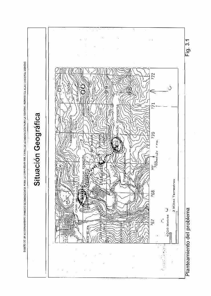
Js S
IEM
EN
S
Situ
ació
n G
eogr
áfic
a
Pla
ntea
mie
nto
del p
robl
ema
Fig
. 3.
1

Planteamiento del Problema Pa.q. 58
3.1.2 DESCRIPCIÓN DEL PROBLEMA.
Como se dijo anteriormente, la Central Hidráulica de Alao recibe alimentación de
agua para mover sus turbinas, del Río Alao. Para esto, el agua es conducida
desde dicho río donde se encuentra la bocatoma a lo largo de un canal de
aproximadamente 13 Km. de longitud (ver línea punteada para seguir la
trayectoria del canal) a una altura de aproximadamente 3050 msnm y a 200 m, de
altura sobre Fúngala. A lo largo de este canal existen algunos puntos importantes
a mencionar: inicio de la tubería de presión, tanque de presión, salida del túnel
18, compuerta de Ishpe y bocatoma.
En la figura 3.2 se puede ver un dibujo- esquemático donde se marca estos
puntos importantes; también se los puede mirar en la figura 3.1 para ubicarlos
geográficamente.
AI final de la tubería de presión se encuentran los generadores que son movidos
por el agua que cae por dicha tubería y por gravedad desde aproximadamente
200m de altura donde se encuentra el tanque de presión. El tanque de presión
almacena un volumen de agua que permite mantener una presión y caudal
estable en la tubería de presión. La salida del túnel 18 (T18) marca el punto del
canal que se encuentra directamente sobre el pueblo de Fúngala. La compuerta
de Ishpe está situada en el punto del canal que pasa por la Quebrada de Ishpe,
su objetivo es impedir el paso del agua por el canal a partir de este punto hacia el
tanque de presión desviándola por un cauce natural como lo es la misma
quebrada (Fig.3.4). La bocatoma es el punto donde el canal toma el agua del Río
Alao.
Como se puede ver en estos gráficos el canal rodea a gran altura las laderas de
la Loma de Cochapamba bajo la cual se encuentra Fúngala. Precisamente este
es el punto de inicio del problema planteado dado que el canal tiene 35 años de
construcción y por lo tanto, en la actualidad, existen tres razones fundamentales
que crean la necesidad de evitar los posibles efectos de un desastre como lo es
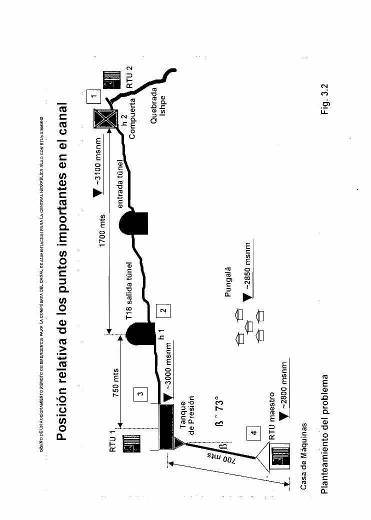
Pos
ició
n re
lativ
a de
los
punt
os i
mpo
rtan
tes
en e
l can
al
RT
U1.
Tan
que
de P
resi
ón
ft~73
<F
únga
la
_ y
-285
0 m
snm
RTU
mae
stro
-280
0 m
snm
Que
brad
aIs
hpe
Co
mp
ue
rta \U
2
Cas
a de
Máq
uina
s
Pla
ntea
mie
nto
del
prob
lem
aF
ig. 3
.2
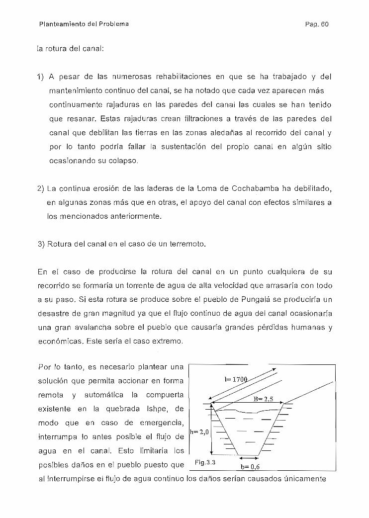
Planteamiento del Problema Pag. 60
la rotura del canal:
1) A pesar de las numerosas rehabilitaciones en que se ha trabajado y del
mantenimiento continuo del canal, se ha notado que cada vez aparecen más
continuamente rajaduras en las paredes del canal las cuales se han tenido
que resanar. Estas rajaduras crean filtraciones a través de las paredes del
canal que debilitan las tierras en las zonas aledañas al recorrido del canal y
por lo tanto podría fallar la sustentación del propio canal en algún sitio
ocasionando su colapso.
2) La continua erosión de las laderas de la Loma de Cochabamba ha debilitado,
en algunas zonas más que en otras, el apoyo del canal con efectos similares a
los mencionados anteriormente.
3) Rotura del canal en el caso de un terremoto.
En el caso de producirse la rotura del canal en un punto cualquiera de su
recorrido se formaría un torrente de agua de alta velocidad que arrasaría con todo
a su paso. Si esta rotura se produce sobre el pueblo de Fúngala se produciría un
desastre de gran magnitud ya que el flujo continuo de agua del canal ocasionaría
una gran avalancha sobre el pueblo que causaría grandes pérdidas humanas y
económicas. Este sería el caso extremo.
Por lo tanto, es necesario plantear una
solución que permita accionar en forma
remota y automática la compuerta
existente en la quebrada Ishpe, de
modo que en caso de emergencia,
interrumpa lo antes posible el flujo de
agua en el canal. Esto limitaría los
posibles daños en el pueblo puesto que
al interrumpirse el flujo de agua continuo los daños serían causados únicamente
Fig.3.3b=Q,6

DIS
EÑ
O D
E U
N A
CC
ION
AM
IEN
TO
RE
MO
TO D
E E
ME
RG
EN
CIA
PA
RA
LA
CO
MP
UE
RT
A D
EL C
AN
AL
DE
ALI
ME
NT
AC
IÓN
PA
RA
LA
CE
NT
RA
L H
IDR
ÁU
LIC
A A
UO
C
ON
RTU
s S
IEM
EN
S
Esq
uem
as d
e la
com
puer
ta e
n la
Que
brad
a Is
hpe
1,80
1,40
Niv
el a
pro
x. a
gua
1,90
Com
puer
ta
Des
fogu
e de
l can
ala
la q
ue
bra
da
Ishp
e(e
)
Que
brad
aIs
hpe
1580
Pla
ntea
mie
nto
del
prob
lem
aF
ig. 3
.4

Planteamiento del Problema Pa.q. 62
por la cantidad de agua contenida en el canal desde este punto hasta la
Quebrada Ishpe (aproximadamente 1700 m.) y que se evacuaría en el caso de
una rotura. Un cálculo simple nos dará el volumen estimado de agua. En la figura
3.3 se puede mirar un corte transversal del canal con su forma y dimensiones
aproximadas.
Para ios cálculos asumimos que existe simetría por lo que la sección tiene la
forma de un trapecio. Así eí volumen contenido por el canal en aproximadamente
los 1700 m. se puede calcular como:
Vcana[= (B + b)*h*l/2
Vcana,= (2,5 + 0I6)*2*1700/2
Vcanal= 5270 ITltS.3
Por su puesto esto significa la peor condición con el canal totalmente lleno. El
volumen calculado es como el equivalente de tres piscinas de 50 m. de longitud
por 12 m. de ancho y 3 m. de profundidad.
Dado que la separación entre el Túnel 18 (T18) y el pueblo de Pungalá es
aproximadamente 3 Km. de ladera (ver Fig. 3.1) se espera que los efectos de
esta descarga de agua sea mínima.
El máximo caudal por el canal es de aproximadamente 4 m.3/seg. y con una
velocidad de 1.2 m/seg. Así el tiempo que se demoraría, en vaciarse el canal al
cerrar la compuerta es de:
V= Uanal/t
donde v= velocidad en mts./seg., t= tiempo en seg. y Icanal= longitud del canal
Entonces:

Planteamiento del Problema Pa.q. 63
t=
t= 1700/1,2
t= 1417 seg. ó 23,62 minutos.
En la Fig. 3.4 se puede ver un dibujo esquemático de la compuerta (d) que
actualmente se encuentra instalada en la Quebrada de Ishpe, como se puede ver
en ese punto el canal se lo ensancha para permitir el descenso de la misma y
cerrar el paso del agua. El cuerpo de la compuerta está hecho de lámina de hierro
de 5/8" de espesor (16 mm.) con un peso aproximado de una tonelada. La
compuerta se mantiene suspendida de unas orejas soldadas al marco de la
misma y sostenida por unos ganchos soldados a un eje (c) que descansa sobre
unos apoyos a y b. Este eje se mantiene trabado para que los ganchos estén en
la posición adecuada para sostener la compuerta. Cuando se desea bajar la
compuerta, el eje es destrabado y girando el volante los ganchos cambian de
posición liberando las orejas de la compuerta y permitiendo que esta caiga por
gravedad. Para controlar la caída de la compuerta, esta es guiada por perfiles tipo
U hasta que llega a la solera del canal cerrando el paso del agua. El agua se
represa en el canal en la parte anterior a la compuerta hasta que dicho nivel
sobrepasa el desfogue (e) y cae a la quebrada Ishpe siguiendo su cauce.
3.1.3 HIPÓTESIS DE TRABAJO.
Si de alguna manera se pudiera determinar el momento en que el canal tuviera
una importante fuga, una rotura o un desbordamiento entonces se podría bajar la
compuerta para interrumpir el paso de agua por el canal y lograr los objetivos
explicados anteriormente.
Esto se cumple si se mide el nivel en dos puntos del canal y luego se compara las
mediciones:
a) en el punto más crítico del canal (sobre el pueblo de Fúngala donde una rotura

Planteamiento del Problema Pa.q. 64
del canal causaría una avalancha)
b) en un sitio donde se pueda tomar una medición de referencia. Cabe indicar
que la sección y dimensiones del canal son uniformes en su recorrido desde la
Quebrada de Ishpe hasta el Tanque de Presión, por lo cualquier punto se podría
tomar como referencia.
Explicación:
Al comparar las dos mediciones de nivel se puede determinar si existe una
diferencia de nivel entre los puntos donde se mide. En condiciones normales y
teniendo en cuenta la uniformidad del canal, idealmente la diferencia de nivel será
0. En la realidad se tiene una pequeña diferencia en exceso por el efecto de
estancamiento que se produce aguas arriba del tanque de presión. En la práctica
y luego de varias mediciones se comprobó que era máximo de 10 cm. (ver Fig.
3.5).
En condiciones de peligro, por ejemplo en el caso de una rotura del canal, el nivel
en el punto de ruptura caería bruscamente en ese punto y hacia atrás, por lo que
una diferencia por defecto mayor a 10 cm. nos alertaría sobre la ruptura y nos
daría la información necesaria para cerrar la compuerta en Ishpe. Otro caso de
peligro se daría por un taponamiento del canal por deslizamientos de tierra o por
basura arrastrada; en este caso el nivel en el punto taponamiento y hacia atrás
subiría por lo que una diferencia por exceso mayor a 10 cm. nos alertaría sobre
un posible desbordamiento del canal, haciéndose necesario cerrar la compuerta
en Ishpe.
Mientras el punto de ruptura o taponamiento del canal esté más cerca al punto de
medición a) entonces la información que indique "problemas" se la tendrá más
rápido y se podrá actuar con mayor prontitud sobre la compuerta de Ishpe para
cerrarla. Esto confirma que el punto de medición a) debe estar en la zona del
canal que está sobre el pueblo de Fúngala.

Planteamiento del Problema Pag. 65
Eí punto de referencia podría ser en la zona del canal cercana a la misma
compuerta de Ishpe.
3.2 REQUERIMIENTOS DEL SISTEMA.
En este apartado y teniendo en cuenta información anteriormente expuesta, se
mencionará algunas de las principales características que debería tener nuestro
sistema automático de control que luego será diseñado. Volviendo a la Fig. 3.4
donde se ven los puntos importantes en el canal, debemos mencionar la siguiente
información adicional tomada de la observación en el sitio:
• La casa de máquinas (4) es el único sitio donde existe vigilancia continua por
los operadores que trabajan en tres turnos durante las 24 horas del día, por lo
tanto cualquier sistema de monitorización y control que se diseñe debe tener la
posibilidad de que toda la información y las posibles acciones de control
manual puedan ser llevadas a cabo desde este sitio.
• En el Tanque de Presión (3) se dispone de una persona que limpia de algas y
basura las rejillas de la tubería de presión, pero no permanece disponible todo
el tiempo. Esta persona también informa cada treinta minutos, por teléfono, a la
Casa de Máquinas el nivel de agua en el Tanque de Presión el cual es
importante para determinar el número de generadores a operar. Este nivel es
hoy medido con un anticuado instrumento de boya. Además, en un futuro se
desea instalar un sistema automático de limpieza de rejillas que sería
controlado desde la Casa de Máquinas. Existe energía eléctrica de 11OV GOHz.
• En la zona del canal a la salida de T18 (2) se observa serios debilitamientos en
las paredes que sostiene y apoyan al canal, esto confirma que este punto es el
punto crítico por su ubicación y por lo anteriormente mencionado.
• La compuerta (1) que cierra el canal debe ser accionada automáticamente, de

Planteamiento del Problema Pap. 66
acuerdo a lo indicado en la hipótesis del trabajo, por una diferencia de nivel
entre los puntos a) y b). Existe alimentación de 11OV. 60Hz. en este sitio. Aquí
también existe una persona que cada 30 minutos informa del nivel del agua en
el canal.
• Experiencias anteriores y referencias de personas del lugar indican que
cualquier tipo de cable que se instale en forma aérea o vista no permanece
mucho tiempo en su lugar, puesto que campesinos del lugar se lo roban. Esto
es algo que se debe tener muy en cuenta a la hora del diseño.
3.2.1 REQUERIMIENTOS TÉCNICOS.
Teniendo en cuenta la información anteriormente expuesta, a continuación se
anotará los requerimientos técnicos básicos del sistema:
1. El sistema debe tener un tablero de control local donde deberá realizarse el
control automático del cierre de la compuerta. Aquí deberá estar el algoritmo
que determinará el momento en que se produzca el accionamiento de la
compuerta y en este sitio se debe disponer de la información de nivel de los
puntos a) h1 y b) h2 (verfig. 3.2). Este debe ser un equipo que funcione por sí
solo sin ninguna dependencia funcional con otro ya que se debe asegurar su
disponibilidad al ser un equipo de seguridad.
2. Se debe tener en Casa de Máquinas la información de nivel del Tanque de
Presión y del nivel del canal en la Quebrada de Ishpe, así como también
monitorear el estado del sistema automático de control de la compuerta para
verificar su correcto funcionamiento. Recordemos que aquí existen operadores
por 24 horas al día.
3. La compuerta también debe poder ser accionada manualmente y en forma
remota desde la Casa de Máquinas en caso de urgencia.

Planteamiento del Problema Pa.q. 67
4. Los ítems 2 y 3 sugieren la ¡mplementación de un sistema de telemando y
telemonitorización que sería el que más se ajuste a las necesidades.
5. Se debe medir nivel por lo menos en el Tanque de Presión, salida del Túnel 18
y Quebrada Ishpe.
6. Si se usa cabíe para la comunicación, este debería ser de características que
le permitan ser enterrado o sumergido en el agua del canal para evitar los
robos.
7. El sistema de accionamiento de la compuerta debe tener alta confiabilidad en
su funcionamiento ya que es parte de un dispositivo de seguridad. El flujo de
agua debe ser interrumpido en un tiempo muy corto.

LJs
SIE
ME
NS
Hip
ótes
is d
e T
raba
jo
Tan
que
de P
resi
ón
dh=
h1 -
h2
Co
nd
icio
ne
s n
orm
ale
s
Ta
nq
ue
de P
resi
ón
Tan
que
de P
resi
ón
dh
=h
1 -
h2
<-0
,1
Co
nd
icio
ne
s de
ro
tura
Co
nd
icio
ne
s d
e o
bst
rucc
ión
Pla
ntea
mie
nto
del
prob
lem
aF
ig. 3
.5

CAPITULO 4
4.1 PRELIMINARES.
4.1.1 DESCRIPCIÓN DEL SISTEMA PROPUESTO.
Basado en los requerimientos técnicos descritos en el capitulo 3, literal 3.2.1 y en
la información obtenida ai estudiar ei sistema de telecontrol de Siemens, SINAUT;
proponemos un sistema de telemetría y telecontrol formado por tres participantes
en una configuración maestro - esclavo (ver Fig. 4.1).
4.1.1.1 Criterios para la configuración básica de las estaciones.
La información de nivel y de funcionamiento de la compuerta podría demorar
algunos segundos en fluir desde su origen al maestro sin ninguna restricción,
puesto que es únicamente informativa o de monitorización. Por otro lado, el nivel
en e! canal tarda varios minutos en producir cualquier variación significativa. Así
mismo, cualquier comando manual para cerrar la compuerta podría demorar
algunos segundos en llegar al esclavo o al destino puesto que un rango menor de
tiempo no influenciará en la velocidad con que la compuerta corte el flujo de
agua, proceso que seguramente está en el rango de varias docenas de
segundos. Por lo tanto, la velocidad de muestreo requerida es baja como es
común en este tipo de sistemas (ver Capítulo 1, apartado 1.2.2) y la elección de
una técnica de.comunicación maestro - esclavo es la más adecuada (ver Capítulo
1, apartado 1.4.1).
La estación maestra será ubicada en la Casa de Máquinas de la Central
Hidráulica de Alao. Será una estación ST115 puesto que se requerirá en este
punto un equipo con mayor capacidad por las funciones que realizará;

I R
TUs
SIE
ME
NS
Arq
uite
ctu
ra d
el S
iste
ma
Pro
pues
to
S5U
115
Par
tele
fóni
co
S5U
100
S5U
100
Mod
em
indi
cado
res
digi
tale
sin
dica
dore
sdi
gita
les
SEÑ
AL
ES
DE
CA
MPO
ED
/SD
/SA
AC
ASA
DE
MA
QU
INA
S
Mod
em
SEÑ
AL
ES
DE
CA
MPO
ED
/SD
/EA
/SA
AT
AN
QU
E D
E P
RE
SIÓ
N
Cas
a de
Máq
uina
s
Dis
eñ
o d
el S
iste
ma
Tanq
ue d
e P
resi
ón
indi
cado
res
digi
tale
s
Mod
em
1SE
ÑA
LE
S D
E C
AM
POE
D/S
D/E
A/S
AA
CO
MPU
ER
TA
ISH
PE
Que
brad
a Is
hpe
Fig
. 4.1

Diseño del Sistema Pa.q. 71
. Coordinar toda la comunicación entre las estaciones.
. Enviar y recibir información desde una interface hombre máquina que podría
ser un panel electrónico o un software.
. En un futuro, este equipo podría tomar tareas de automatización que son
necesarias implementar para modernizar algunos de los procesos de control de
los generadores. Por ejemplo, se podría conectar los generadores en paralelo
de acuerdo a la disponibilidad de agua en el tanque de presión y de las
condiciones de la carga. Por lo tanto, dejaremos disponibles en la
configuración de esta estación; una mínima cantidad de puntos de E/S.
El tablero que contenga la estación se lo ubicará en el cuarto de control de la
Casa de Máquinas para que la información este directamente disponible a los
operadores de la Central Alao.
El primer esclavo estará ubicado en el tanque de presión. Será una estación de
telecontrol ST100 dado que la función principal de esta es transmitir la
información del nivel del tanque de presión hacia el Casa de Máquinas. De esta
forma se logra los siguientes objetivos:
• Cambiar el antiguo medidor de nivel de boya por otro de moderna tecnología,
con lo cual se tendrán mediciones precisas.
• La información de nivel se transmitiría automáticamente hacia la Casa de
Máquinas.
Adicionalmente, en el futuro se tiene pensado instalar un equipo que
automáticamente limpie los desechos y algas detenidos en la rejilla de acceso al
túnel de presión, por lo que en este caso también, dejaremos algunos puntos de
E/S digitales, además de una entrada analógica para el sensor de nivel.
Dado que el trabajo que tiene que realizar este equipo no es complicado, su CPU
podría ser modelo 102U.

Diseño del Sistema Pag. 72
El tablero que contenga esta estación se puede instalar en un cuarto vacío que
existe en la caseta ubicada en el sitio.
El segundo esclavo estará ubicado geográficamente en la Quebrada de Ishpe,
junto a la compuerta que se accionará. Será una estación ST100U. Su función
local principal será accionar la compuerta en caso de emergencia y basado en el
algoritmo que se implementará en él (se explicó en el Capítulo 3 apartado 3.1.3).
Para ello, en esta estación se debe disponer de la información de nivel a la salida
del Túnel 18 (punto crítico) y del punto de referencia. Ahora bien, la distancia del
Túnel 18 al tanque de presión es de 750 mts. y a la Quebrada de Ishpe de 1.700
mts. por lo que la señal de nivel de este punto se debería llevar hacia la primera
estación esclava para evitar, en lo posible, que la señal análoga entregada por el
sensor de -nivel se degrade. Luego transmitirla digitalmente por el medio de
comunicación entre las estaciones al segundo esclavo. Otra solución sería
colocar en este punto un cuarto esclavo que recoja la señal de nivel y la transmita
digitalmente por el medio de comunicación entre estaciones; sin embargo el costo
de esta estación no se justificaría, únicamente para recoger una señal de nivel
sobre todo si existe otro medio para hacerlo: la experiencia indica que es posible
transmitir señales analógicas de corriente a larga distancia siempre y cuando se
tome ciertas precauciones técnicas.
No obstante y por motivos de seguridad, tampoco es buena idea que la primera
estación esclava recoja la señal de nivel de T18 y la envíe al segundo esclavo;
puesto que en caso de un terremoto por ejemplo, la comunicación puede ser
interrumpida y no se tendría la información de nivel del punto crítico en la estación
de Ishpe. Así pues la única alternativa es llevar esta señal directamente a través
de 1.700 mts. hasta la Quebrada de Ishpe. Como ya manifestamos esto es
posible bajo ciertas condiciones que revisaremos posteriormente.
La estación en este punto debe tener por lo menos dos entradas analógicas y
algunos puntos E/S digital para las labores de activar la compuerta. Las funciones

Diseño del Sistema Pag. 73
que tiene que manejar esta estación obliga a que su CPU sea la de mayor
capacidad: CPU 103U.
Para la ubicación del tablero se deberá construir una caseta.
4.1.1.2 Criterios para escoger la tecnología de comunicación.
Para escoger la tecnología a utilizar en el sistema, los criterios mas importantes
son la ubicación del sistema de telemetría (Qué recursos de comunicación se
dispone en sitio?) y si el costo de implementar cualquiera de ellos se justifica para
un proyecto como el aquí analizado.
RADIO:
Mirando la Fig. 3.1 y analizando las líneas de nivel se puede ver claramente que
no existe "línea de vista" entre la estación que se ubicaría en la Quebrada de
Ishpe y la Casa de Máquinas donde se encontraría el maestro de nuestro
sistema. Así cualquier sistema de radio que se ¡mplementase requeriría de una
repetidora la cual debería ubicarse por ejemplo en la Loma de Tianguche. De
hecho se realizaron pruebas con radio en bandas UHF y VHF donde la recepción
de voz era prácticamente nula, por lo que la repetidora es una necesidad. El
sistema de comunicación entonces se vuelve costoso, peor aún si se implementa
radio enlace de datos. El radio troncalizado no está disponible en la zona y tiene
la misma necesidad de repetidora.
Por lo tanto, esta tecnología no es práctica en nuestro caso por el costo.
FIBRA ÓPTICA, SATÉLITE, ETC.
La FO y el satélite son sistemas de comunicación costosos y requieren personal
calificado en esas tecnologías de comunicación para su mantenimiento.
Esto hace que definitivamente no se los considere como una alternativa viable.

Diseño del Sistema Pap. 74
LINEAS TELEFÓNICAS:
En la zona, por ser un sitio rural, no existen líneas telefónicas públicas por lo que
nos queda como la única alternativa viable y relativamente barata una línea
privada dedicada. Sin embargo, como mencionamos en el Capítulo 3 apartado
3.2.1 debemos tener cuidado al elegir las características del cable para la
comunicación ya que debe ser enterrado o sumergido.
Dado que no se requiere velocidad alta de muestreo y que solamente tenemos 3
participantes, una comunicación "half dúplex" a dos hilos es suficiente.
4.1.1.3 Respaldo de energía.
Como se menciona en el Capítulo 3 ítem 3.2, en cada punto donde se colocará
una estación de telecontrol (Fig. 4.1) existe energía eléctrica de 11OV 60Hz
disponible para alimentar las estaciones. Sjn embargo, debemos prever que esta
alimentación se interrumpa por razones predecibles o impredecibles:
• Interrupción de la alimentación por daños en la red
• Interrupción de la alimentación por racionamientos
• Interrupción de la alimentación por movimientos telúricos
. Etc.
Al ser un sistema de seguridad se debe garantizar su funcionamiento aún cuando
se interrumpa la alimentación, principalmente en la estación de la Quebrada de
[shpe que tendrá la responsabilidad de accionar la compuerta. Experiencias
anteriores con los racionamientos en ese sector nos dan un parámetro de
referencia respecto a lo que podría durar una interrupción por ese motivo: 18 h.
En el caso de una interrupción por daños en la red es imposible predecir el tiempo
que se demoraría en reparar una avería puesto que depende de las
circunstancias en que se produjera por lo que 18 h, sigue siendo un tiempo
razonable. Sí la interrupción se produce por un terremoto sería suficiente disponer
de unos minutos (por ejemplo 10 minutos) para ordenar manualmente el cierre de
la compuerta y prevenir cualquier problema; pero para esto las tres estaciones

Diseño del Sistema Pap. 75
deberían estar activas varios minutos después de la interrupción. Pero si el
fenómeno natural además de interrumpir la alimentación de energía, acarrea una
interrupción de las comunicaciones entre las estaciones (por ejemplo rotura del
cable de comunicación) entonces manualmente sería imposible accionar la
compuerta y por lo tanto se debería dar a la estación de la Quebrad Ishpe una
autonomía suficiente para mantener la posibilidad de accionar la compuerta en
caso de peligro; por ejemplo las 18 horas.
Ahora, tenemos que tomar en cuenta que cualquier sistema de respaldo de
energía que adoptemos deberá suministrar la energía necesaria para accionar la
compuerta.
4.1.1.4 Tipo de accionamiento para la compuerta.
Si se utiliza UPS (uninterrumplible power supply) como sistema de respaldo de
energía entonces se tendrá limitaciones al escoger el tipo de accionamiento de la
compuerta puesto que es conocido que la energía que deberá almacenar el
banco de baterías determinará su costo. Si la compuerta es accionada
eléctricamente con un motor, este deberá tener una potencia suficiente para
elevar o bajar la pesada compuerta (a pesar de poder utilizar un motoreductor) y
el banco de baterías debería suministrar la energía necesaria para el arranque del
motor y para mover la compuerta.
El banco de baterías para suministrar esta energía sería muy costoso. Otra
opción es utilizar un sistema de energía alternativo como un motor- generador a
diesel; sin embargo sería un sistema que necesitaría mucho mantenimiento en un
lugar tan apartado y no estaría disponible con la suficiente rapidez en caso de
emergencia y esto sin contar con el costo.
Para mantener bajo el costo dei sistema, se podría mirar la posibilidad que el
sistema de respaldo de energía mediante UPS solo guarde energía para la

Diseno de! Sistema Pag. 76
estación de telecontrol (electrónica de la estación) y que el sistema de
accionamiento de la compuerta no sea eléctrico sino de otro tipo de manera que
también el almacenamiento de energía necesaria para asegurar el cierre de la
compuerta no sea en un medio eléctrico.
Especialistas en ingeniería mecánica sugieren que podría utilizarse un
accionamiento neumático donde la energía necesaria para accionar la compuerta
estuviera almacenada en el tanque de reserva de un compresor en forma de
presión. Esto es posible puesto que en el lugar se dispone de alimentación
eléctrica para el funcionamiento del compresor. En caso de falla de esta
alimentación, el sistema seguiría disponible puesto que el tanque de reserva del
compresor se encargaría de mantener la presión.
Así la solución adecuada para el accionamiento de la compuerta parece ser un
sistema neumático.
4.1.2 REQUERIMIENTOS DE LOS POSIBLES USUARIOS.
Visitando el sitio y conversando con los posibles usuarios del sistema, a
continuación se enumera algunos requerimientos que a su juicio debería
incorporar el sistema;
» La forma más rápida y segura de cerrar la compuerta en caso de emergencia
sería que esta cayera por gravedad desde su posición de suspensión (ver Fig.
3.4) y guiada por los perfiles tipo U alcance la solera del canal. Este es e!
método manual que se utiliza en la actualidad para cerrar el canal (ver Capítulo
3 apartado 3.1.2) y que por lo tanto se ha comprobado que funciona
adecuadamente y sin fallos debido al gran peso de la compuerta.
• Cada tablero de las estaciones de telecontrol deberá tener alarmas luminosas
por medio de LEDs.
• Cada tablero de las estaciones de telecontrol deberá tener tres indicadores

Diseno del Sistema Pap. 77
digitales para exhibir la información de nivel de: túnel 18, referencia en
Quebrada Ishpe y de tanque de presión.
• Cada tablero de las estaciones remotas deberá tener una alarma audible.
• Cuatro relés para conectar o desconectar los generadores en función del Nivel
en el Tanque de Presión
Adicionalmente, se recalca que los operadores de la Central Alao y que por lo
tanto supervisarán el sistema de emergencia son personas con poca instrucción
técnica que realizan sus tareas rutinariamente. Por lo tanto, al diseñar el sistema
se tendrá como condición adicional el que los tableros sean muy fáciles de
operar.
4.2 DISEÑO.
4.2.1 DISEÑO DE LOS TABLEROS DE LAS RTUS.
4.2.1.1 Dimensionamiento de las RTUs.
Para el dimensionamiento de la periferie de las estaciones de telecontrol el
criterio es tener un 30% de puntos de E/S extras para ser utilizadas en el futuro.
RTU DE LA QUEBRADA DE ISHPE
TIPO E/SEntradasdigitales a 24VDC
DESCRIPCIÓN• Fines de carrera para indicación compuerta cerrada o abierta• Pulsante de activación manual de la compuerta (Emergencia). Reconocimiento de alarmas• Reposición de alarmas. Control mantenimiento o normal
SUBTOTAL:30%:
TOTAL:
CANTIDAD21111628

Diseno del Sistema Pa.q. 78
TIPO E/SSalidasdigitales a24 VDC
Entradasanalógicasde 4 ... 20mA.
Salidasanalógicasde 0 .... 10V.
DESCRIPCIÓN. Alarma audible• Alarmas y señalizaciones visuales
para: Estado de sensores de nivelEstado de CompuertaEstado de la ComunicaciónSistema en mantenimiento
• Acionamienío de compuertaSUBTOTAL:
30%:TOTAL:
. Nivel de• Nivel de
referenciaTúnel T1 8
SUBTOTAL:30%:
TOTAL:
. Nivel de
. Nivel de* Nivel de
referencia (indicador digital)Túnel T18 (indicador digital)Tanque de Presión (indicador digital)
SUBTOTAL:30%:
TOTAL:
CANTIDAD16
293
12
11
213
111
314
RTU DE TANQUE DE BALANCE:
TIPO E/SEntradasdigitales a 24VDC
Salidasdigitales a24 VDC
DESCRIPCIÓN. Pulsante de activación manual de la compuerta (Emergencia)• Reconocimiento de alarmas. Reposición de alarmas
SUBTOTAL:30%:
TOTAL:
. Alarma audible
. Alarmas y señalizaciones visualespara: Estado de sensores de nivel
Estado de CompuertaEstado de la ComunicaciónSistema en mantenimiento
SUBTOTAL:30%:
TOTAL:
CANTIDAD111
314
16
729

Diseño del Sistema Pag. 79
TIPO E/SEntradasanalógicasde 4 ... 20mA.
Salidasanalógicasde 0 ... 10V.
DESCRIPCIÓN• Nivel de Tanque de Balance
SUBTOTAL:30%:
TOTAL:
. Nivel de referencia (indicador digital)
. Nivel de Túnel T18 (indicador digital)
. Nivel de Tanque de Presión (indicador diqital)SUBTOTAL:
30%:TOTAL:
CANTIDAD1
101
111314
RTU DE CASA DE MAQUINAS:
TIPO E/SEntradasdigitales a 24VDC
Salidasdigitales a24 VDC
Salidasanalógicasde 0 .... 10 V
DESCRIPCIÓN. Pulsante de activación manual de la compuerta (Emergencia). Reconocimiento de alarmas. Reposición de alarmas
SUBTOTAL:30%:
TOTAL:
• Alarma audible. Alarmas y señalizaciones visuales
para: Estado de sensores de nivelEstado de CompuertaEstado de la ComunicaciónSistema en mantenimientoNivel Max. en Tanque de PresiónNivel Min. en Tanque de Presión
. Cuatro relés para conectar o desconectar los generadores enfunción del Nivel en el Tanque de Presión
SUBTOTAL:30%:
TOTAL:
. Nivel de referencia (indicador digital)* Nivel de Túnel T18 (indicador digital). Nivel de Tanque de Presión (indicador diqital)
SUBTOTAL:30%:
TOTAL:
CANTIDAD111
314
18
4
13417
111314

Diseño del Sistema Pag. 80
Se define como tensión de las E/S Digitales 24VDC porque es un nivel de tensión
seguro para mantenimiento y operación. Además es un voltaje estándar en
cuanto a tarjetas para las estaciones SINAUT ST.
Del mismo modo, se ha escogido tarjetas de corriente de 4 a 20 mA. puesto que
como se describió anteriormente la señal de los medidores de nivel deben viajar
algunos cientos de metros. Con una señal de corriente es posible llevar la
información de nivel a través de esta distancia tomando ciertas precauciones.
A continuación y utilizando tablas de configuración provistas por el fabricante
como ayuda, determinaremos todas las partes que integrarán las estaciones de
telecontrol:
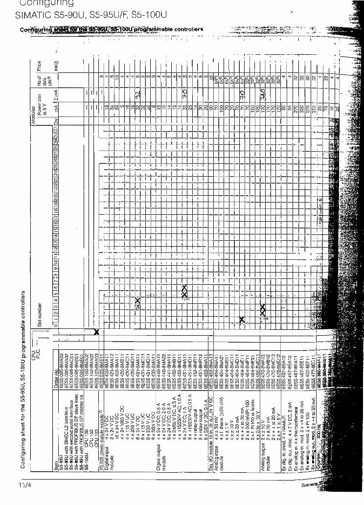
ConfiguringSIMATIC S5-90U, S5-95U/F, S5-100U
i J.J. 1-1—L i- L.Lr¡ M >
11/4

üoníiguringSIMATIC S5-90U, S5-95U/F, S5-100U
n r! '+!
— - 'Bt«- I <iP l
ETcO
ft
E 0
1"
tt
i-K' h:
r^fer--^ t
gg- ^
•f S".
jjl «i
£ r
K •-'K' f:
1'm *m r.
i ^fe' i-
i r-
fi ht t-S i
t ^~fcI*- *-¥ •í&* •
$
fe
t" <
? 13t- rafc ca
t tnCO
í LUá uj
r1sÍJ-
í
"í Oír 3i TD
OE
f 0'"- í
3
¿ CO
T TCO
ID OOJ OJ
—
--
"'
•
rrCD
OPJ
CD
OOJ
-
-
'
TCO
oOJ
T(O
IDf~-
1
TCD
OCJ
1
1
OJco
oin
_
TCO
oSoT
•íTCD
Otr
!
IX
1
co
ooco
-
¡
...
6E
S5
33
0-8
MA
V6
ES
52
62
-BM
A1
Íaanost
ics
module
ised-lnnn
IP
262:
K c
on
tro
ller
¿u
cj n
5 <S Sco caÓJ CÓCD taOJ OJLD inco coLU LUCD CD
OJ 1- T- T- I- T- Or— O i— t— OJ i— O< < < < <í CO <
S S S S S S wCO CO CO CO CQ CO ,J
CD CD ID CD OJ 0] ;?oj oj rj oj 10 uj win in in in in in n(73 CO CO CO CO CO LU LU LU LU LU LU (£CO CO CD CD CD CD CD
cont
rol m
odul
e [P
262
; S
con
trol
ler
IP 2
63 p
osili
onin
g m
odul
eIP
264
ele
ctro
nic
cam
con
trol
ler
IP 2
65 h
igh
spe
ed s
ub c
ontr
olIP
266
pos
ilion
ing
mod
ule
IP 2
67 s
tepp
er m
otor
con
irolle
rC
omm
unic
a-
CP
521
SI
tions
C
P52
1 B
AS
ICor
oces
sor C
P 2
4339
>
1 1
1
XXXX
1
I
1
-
1
1
1
1
1
I
íi
- I
1
1
1
1
]
1
*- _ w ^ i- i-t- E; cj ^_ T- oj< J < < CQ CD2 £ s S s sto co co co co ca
o o o o o or~- r- r- r- r-~ r—in m in tn in inCO CQ CO CO CO COLU LU LU LU LU LUCO CO CD CD CO CD
Bus
unit
(scr
ewco
nnec
tion)
Bus
uni
t (s
crew
conn
ectio
n}8)
Bus
unü
(cr
imp
conn
ecíio
n)8'
Exb
usu
nil
Inte
rrup
t bu
s un
ií (s
crew
conn
ectio
n)11
Inte
rruo
t bu
s un
it fc
rimo
conn
ectio
n)1)
1 1i 1
T- Tj- -T
•^oT'rr
"c^rT
"rPóT
^">c>r'cy~
^'fT'^r
^"c^tvT
í" ST oí
- c-i cj
— "' 'T -T
_
-. — -J
"íT'c'r'
^ ?J CM
< < 52 2iico co to
6ES
5315
6ES
5316
6ES
5316
IM31
5 in
terí
ace
mod
ule
IM 3
16 in
terí
ace
mod
ule
IM 3
16 in
terí
ace
mod
. (e
nh.
EM
C le
vel)
S
A-i
tha
utP
S9
35
/~ 1
Aw
ith P
S 9
35 /~
2.5
Ail
curr
ent
£
"£
i Max
. co
nfíg
urat
ion:
4 t
iers
(on
e IM
316
per
t
co
tnCD
enuCD-Co
1) F
or S
5-1
OO
U w
ith C
PU
103
onl
y; o
péra
les
as n
orm
al b
us u
niti
n a
t
2 Siemens ST 50 -1998
pccoCJ0)JDCCD
n b
e c
onne
cled
in b
e c
onne
cted
3: 2
CP
s ca
n be
con
nect
edad
ditio
nal I
/O m
odul
es:
3 C
Ps
c
u u T- 3tn Q- — ) O
CU U ¿eu -05?! O CJ co¿ o o om *~ *~ *~9Z)D Z)in CL CL 0_COCJOO
67r
each
act
ive
chan
neea
ch a
ctiv
e ch
anne
lC
PU 1
00ed
EM
C le
vel
O !- -1- O— o -> c
4) M
áxim
um p
erm
issi
ble
num
ber
(£.):
S5-
95U
: 70
4 da
ta b
its.
max
. 51
2 o
í whi
ch ír
om a
nalo
g m
odul
es 5
} 1
6 b
iS
5-10
0U w
ith C
PU
100
: 25
6 da
ta b
its,
max
. 12
8 oí
whi
ch t
rom
ana
log
mod
ules
6)
8 bi
tC
PU
102
: 48
0 da
ta b
its,
max
. 25
6 of
whi
ch í
rom
ana
log
mod
ules
7)
Not
\U 1
03:
704
data
bits
, m
ax.
51 2
oí w
hich
íro
m a
nalo
g m
odul
es 8
} En
hE
u c.- o
•^ en iQ. CD
^r 0
Ord
er N
o.ECD
CD
O
CD jr0 U
Q. O
:>.O
Ord
er N
o.
Acc
esso
ries
ítem
T_
6E
S5
49
0-B
MB
1
>íuW
C'o.óT
O
Fron
t co
nnec
6ES
5375
-1LA
15M
emor
vsub
mod
ule
EP
RO
M.
8 K
bvte
1
^_
6ES
5 49
0-8M
B2
CL
OW
C'QóOJ
CO
6ES
5490
-BM
A1
coo
Eu
'Qó• r
o
Fron
t co
nnec
co
6ES
5490
-SM
AC
co
go
ti
5
Ca
$
6ES
5490
-8F
B1
at
c'QóT
6ES
5 75
0-2A
A1
o3Q
C'QoS
Sub
D c
onne
cto
6ES
5750
-2A
B1
0-i:oOff>c"Qen
6E
S5750-2
AA
2
cac
iñ
3
6ES
5 37
5
o
JDXLCO
2OceQ_LU
TI
^T
5
mcoIDir.LUÍO
EP
RO
M,
32 K
bvte
1
Ccir.C"JinV,LUco
co
J3
OJ
SOCED_aiai
OJ
oirrjirjcoLUco
CD
JDX.T
SOa:Q_aiai
coCcirCJmcr.ai(D
o
.c
CO
¿OCE0_aiLU
•Q-Ccir
mcr.u,CD
EE
PR
OM
. 16
Kbv
te
Cl
<
oorn
incr,aID
£a"cJ3C
5urom
6E
S5930-B
MD
12
4V
AC
/DC
, 1
A
Q)
>
5
ü_
">c.o
oo10u\1
<OJ
CJ
u<>TOJ
m<ócoco
LUCO
<T
o"
24
VA
C/Í
6EW
1 38
0-4A
BC
<o
o"
24
VA
CA
<2coo
IDcr.a(D
DIN
rai
l 483
mm
/18.
84 in
lor
19 in
cab
lnet
s
1CQ
o
mo:atD
§c
530
mnV
20.6
7in
for
600m
rrV23
.4
co<2coo
mc/:aCD
@uc
B30
mnV
32.3
7in
for
900m
nV35
.1
-T<
2mo
unc/aCD
c.03
t
EoooOJ
.ir"cca
<LUenr-
mCOLUCD
C_Q
rraQ
L
tí pU
B Z
SU
C
her
see
Sec
ti
O
1coOJ
IDCOaCO
ce
íinoi"oa
cu.ücauo.5LCU£C0CJO
r-
oIDamCO
cvi
IDtoLUco
O.
cr
iro
oou_mCO
01
incoLUCD
T
C£
iOm
oomoCO
0)
tncrLUto
10.0
m/3
2.3í
t I
V\L A,2
i
E3
CO
11/E

.rf f»
*'íw
,gr-'iB
'**M
r'ii .
o
CR
700
-2 s
ubra
ck fo
r S
5-11
5U a
nd S
5-11
5H
Com
pone
nt lis
t G
ener
a! a
cces
sorie
s (N
o., s
ee b
elow
) - —
-A
dapi
er c
asFa
n su
bass
Mod
ule
tvoe
CP
U
CP
U 9
41. C
PU
942
CP
U 9
43, C
PU
944
with
V2 ¡n
lerf
aces
CP
U 9
45D
igita
l 3
2x
24
VD
Cin
put
32 x
24
V D
Cm
odul
e 1
6x2
4 ..
.48
VU
C1
6x
48
...6
0 V
DC
8 x
24 V
DC
16
xl1
5-V
UC
16
x11
5V
UC
8x1
15
VU
C1
6x2
30
VU
C1
6x2
30
VU
C8
x 23
0 V
UC
32
x5
...1
5V
DC
Dig
ital
32 x
24
V D
C; 0
.5 A
outp
ut
32 x
24
V D
C; 0
.5 A
mod
ule
16 x
24
V D
C ..
. 60
V; 0
.5 A
16
x2
4 V
DC
, 2
AB
x 24
V D
C; 2
A1
6x
48
... 1
15V
AC
; 1 A
16
xl!
5V
...2
30
VA
C;1
A8
x1
15
...
23
0V
AC
;2A
32
x5
... 2
4 V
DC
; 0.1
A1
6 x
30
V A
C r
elay
con
tacl
sB
x 30
V D
C/2
50 V
AC
rel
ay c
onta
cls
1 G
x 25
0 V
AC
rel
ay c
onta
cts
16
x2
4V
DC
:2A
Dig
ital
24 V
DC
: 1 6
inpu
ts, 1
6 o
utpu
ts 0
.5 A
inpu
t/ 24
V D
C 1
6 in
puts
. 1 6
out
puts
0.5
Aou
tput
24
V D
C; 1
6 in
puts
. 1 6
out
puts
0.5
Am
odul
e 24
VD
C;
8 in
puts
, B
ou
ipu
ts2
.5A
24 V
DC
: 24
inou
ts. 1
6 o
utou
ls 1
.5 A
Ana
log
8 in
puts
inpu
t 8/
16in
puls
mod
ule
4 in
puts
B/1
6ino
u!s
Ana
log
8 ou
tpul
s, ±
10
V; 0
... 2
0 m
Aou
ipul
B
out
puls
, ± 1
0 V
mod
. B
out
puts
. 1 ..
. 5 V
; 4 ..
. 20
mA
Pow
er o
uput
mod
uleb
)-b)
(m
ax. 1
.25
A}
fmax
. 2.5
A)
Inte
lli-
IP 2
40 fo
r cou
nlin
g, p
os.
dec.
and
pos
.ge
nt
IP 2
41 fo
r cou
ntin
g an
d po
s. d
ec.
5'I/O
IP
242A
for c
ounl
ing5
)-6)
mod
ules
!P
242
B fo
r co
untin
g5)
IP 2
43 to
r an
alog
val
ué p
roce
ssin
gIP
244
tor t
empe
ratu
re c
ontr
olIP
246
l/A
tor
cont
r. p
os.,
incr
emen
lal
| IP
246
1/A
foi c
onlr
pos.
, abs
olut
oIP
247
for co
nir.
pos
.I
IP
252
tor c
íoee
d-lo
op c
ontro
l\P
260
for r<
igh-
8p8B
d el
, -lo
op c
ontro
lA
. , ;
\P
2ev-
tarp
rapo
rtfo
ntng
^^^T
^^
1^^
1^^
1^^
'
'
Sw
É^^
SS
ÍSfe
fting
requ
ired
(•)
ambl
y re
quire
d (•
) -
Ord
er N
o.6E
S5
94.-
7UB
116E
S5
94.-
7UB
.16E
S5
945-
7UA
.36E
S54
20-7
LA11
6ES
5430
-7LA
1Z6E
S54
31-7
LA11
6ES
5432
-7LA
116E
S54
34-7
LA12
6ES
5435
-7LA
116E
S54
35-7
LB11
6ES
5435
-7LC
116E
5543
6-7U
YI1
6ES
5436
-7LB
116E
S54
36-7
LC11
6ES
5434
-4U
A12
6ES
5441
-7LA
126
ES
54
51
-7L
A1
6ES
5 45
3-7L
A1
16E
S54
54-7
LA12
6ES
5454
-7LB
116E
S54
55-7
LA11
6ES
5456
-7LA
116E
S54
56-7
LB11
6ES
5457
-7LA
116E
S54
58-7
LA11
6ES
5458
-7LB
116E
S54
58-7
LC11
6ES
5453
-4U
A12
6ES
5482
-7LA
116E
S54
B2-
7LF1
1G
ES5
4B2-
7LF2
16E
S54
82-7
LF31
6ES
5 4B
5-7L
M 1
6ES
5460
-7LA
136E
S54
65-7
LA13
6ES
5 46
3-4U
.12
6ES
5466
-3LA
116E
S54
70-7
LA12
6ES
5470
-7LB
126E
S54
70-7
LC12
6ES
5776
-7U
M3
6ES
577B
-7LA
136E
S5
240-
1AA
216E
S52
41-1
AA
126E
S52
42-1
AA
326E
S52
42-1
AA
416E
S52
43-1
AA
136E
S52
44-3
AB
316E
S5
246-
4U .
16E
S5
246-
4U 1
6ES
5247
-4U
A31
6ES
5252
-3A
A13
6ES
5260
-4U
A11
6ES
5261
-4U
A11
QE
S52
81 4
U.1
2
iHBi
BB
BglBM
iliBBSiiB
E a
Hjm
^ ja
mar
e^
•tV3B
nH
iHH
BH
HM
MH
MBH
HM
H0lraiB
n$!
-' • • •
~~" 7~
~
•
-
•
-
• •
3 3 3 b 5 5 5 5 5 5 5 5 5 5 G b 5 5 5 5 5 5 5 5 5 5 5 6 b 5 5 5 5 5 5 6 •1 5 5 5 5 5 / 7 7 7 4 7 7
Slo
t N
o.PS Cro
ss
CP
U0
mod
ules
req
u
1
- -
.. . -
. ..
'
i
7 ¡
7 1 '
"1
3/7 7 7
-f~ i pa
-
I
• •
— -
fc'¿
r*d
(ti'»?
"ír.\
áMJÍ
Ü»,
i2
3A
red
. — —
iL
._
._
!
•xr
• * 'r .i • '
•, -.
. .
r^B
. '.
-,.'•
-"
-'ít&
¿-\?
'.
5
. .
.
1 i 1 j 1 1
fiSli
rx*w
u
Ife&
fe^
— •
-• ~
- •
-
- iF¿T~
•*'•'• «
W1
•¿¡¿
¡3'í*
6
' 5
,"
" S
i'51
"-s
r51
""
51
IM
1 M
1
51
111
51
"' 51 5i 5) 5)"
51"
•51 bl f
bl 51 :
""
51 51 '
b)
'
"
Si"
- 5-
.-
- sr
'-
5i sr "51* 51
— '
51 '
"
51"
1 5i w
i i 1
iM!
Mod
ule
Qly.
Cur
rent
con
s.
atS
VA
Sum
A0
16
0.2
/0.4
5
0.2
/0.4
50.5
/1.2
5"
O'.O
OS
0.0
05
0.0
05
0.0
05
0.0
7
0.0
05
0.0
05
0.0
05
0.0
05
0.00
50.
005
0.08
0.01
0.1
0.05
0.05
0.17
50.
070.
035
0.1
0.05
0.05
0.05
'0.1
20.
05
Ói¡
L
10.0
5 !
0 O
5
,
0.05
0.15
0.1
0.15
0.15
0.2
0.7
0.25
0.25
0.25
0.09
0.09
0.8*
)1 .O
í
1.1
1.1
0.6
0.4 1.3^
1 3
2)0
8")
/
•
0.2
.51
?-3
1
*=•«&
1
—
- -i
;¿í4
tá
U 0
5 !
u.e
;O
'S3!
0-75
J! I
Pric
e
each
- ¿¿ikik.i.j'í.
s; JV; I
C/3 eno o D
Pfl
en (Q
C c
5 f
i"~n
CQ

6FM
1 72
1-3A
A20
6FM
1 72
3-3.
A.O
72Í t
or c
onfr.
VVF
72&
ftgr c
gntr.
CP
523
for po
ínl-í
o-po
íní I
rnk
Com
roü-
ocat
/ons
proc
es-
SO
fS
6ES
5523
-3U
A11
6ES
5524
-3U
A15
6ES
5544
-3U
.11
6AV
1 24
2-O
AB
.O6A
V4
OI2
-OA
A10
.0A
BO
6ES
5S30
-7U
126E
S55
30-3
LA12
6GK
1243
-OS
A10
6GK
1 54
3-1A
AO
O6G
K1
143-
OA
A01
6GK
1 14
3-O
AB
016G
K1
147-
3MAO
O
CP
524
for p
oinl
-ío-p
oint
link
CP
544
for p
ojnl
-to-p
o¡nl
link
CP
527
íor
HM
IC
P 5
28 fo
r HM
I dig
ital o
r an
alog
CP
530
íor S
INE
C L
l, b
lock
-type
CP
530
(or S
INE
C L
1. c
ompa
cíC
P 2
430
(I/O
. pag
e op
erat
ion)
f. A
S ¡n
terí
CP
543
1 FM
S/D
P fo
r P
RO
FIB
US
CP
143
0 TF
for In
d. E
ther
net
CP
l43
0F
Tfo
rln
d. E
ther
net
CP
147
3 M
AP
for
Ind.
Eth
erne
t5)
Spe
cial
appl
ica-
tions
IM 3
04 in
terf
ace
mod
ule
IM 3
05 in
terí
ace
mod
ule
IM 3
06 ¡n
terfa
ce m
odul
eIM
307
inle
rface
mod
ule
IM 3
08 in
terfa
ce m
odul
eIM
30B
-C in
terfa
ce m
odul
e
6ES
5304
-3U
B11
6ES
5305
-7U
116E
S5
306-
7LA
116E
S53
07-3
UA
116E
S53
08-3
UA
126E
S53
08-3
UC
11on
lyfo
r C
PU
942H
S5-
115H
IM
304
¡ni.
mod
ule.
CC
¡ni..
2nd
CC
IM 3
24R
ínt.
mod
.. C
C ín
l.. Is
t CC
6ES
5942
-7U
H11
6ES
5304
-3U
B11
6ES
5324
-3U
R11
fota
l cu
rren
! for
cen
tral
con
trol
ler
1) D
epen
dmg
on
the
inte
rface
mod
ule
2)
With
out s
enso
r sup
píy
3) A
llow
ance
mus
í als
o be
mad
e fo
r the
resp
ectiv
e se
nsor
mat
chin
gm
odul
e fo
r eac
h c
hann
el u
sed
4)
Pow
er c
onsu
mpl
ion/
curr
enl s
uppl
y to
EU
5)
Ñor
for S
5-11
5H6)
Nol
¡n c
onju
nctio
n w
ith C
PU
945
7)
For
pow
er s
uppl
y oí
a tr
ansc
elve
r m
ax. 4
,2 A
8)
Not
for
S5-
115F
Tota
l cur
rent
for
the
cent
ral c
ontr
olle
r an
d ce
ntra
l exp
ansi
ón u
nlts
[car
ried
forw
afd
(rom
the
conf
lgur
ing
she
ets
for c
entral
EU
sJIs
tEU
2ndE
U
3rd
EU
C
C
PS 9
5 1
pow
er s
uppl
y m
odul
eup
to 3
A:
6ÉS
5 95
1-7L
B2
1 fu
p to 7
A (P
LC w
ithou
l tan
) or up
tóT
SÁ
lPLC
with
/ají)
: 6E
S5
951-
7Í-0
21A
7ND
S I/
-7N
041 " i
"'
• ~
" .
-
- -
-—
*
—
~r..
Acc
esso
rles
1
Ada
pter
casi
ng2
Long
(an
sub
asse
mbl
y 24
V D
C o
r 23
0 V
AC
3 R
AM
. EE
PH
OM
, EP
RO
M m
emor
y su
bmod
ule
4 Fr
ont c
onne
cíor
K, c
rimp/
scre
w c
onne
ctio
n5
Fr
onl c
onne
ctor
490
,cr
imp/
scre
w/s
prln
g-íy
pe c
onne
ctio
n6
Fro
ntco
nnec
tor 4
97, c
rímp/
scre
w c
onne
ctio
n7
O
iher
6ES
5491
-OL1
16E
S5
9B1-
OH
A.1
6E
S5
37
.-6X
X3
068/
6XX
3 08
16E
S5
490-
7 ..
. 1
6E
S5
49
7-4
U..
.
4 4 a ±
-
Sum
[_
Tota
l pric
e o
f exp
ansi
ón u
nits |
7ota
l pric
e

Diseno del Sistema Paq. 85
ACLARACIONES:
. El TIM011B SL es esencialmente una CP521 con "firmware" especializado
. El TIM011 es esencialmente una CP524 con "firmware" especializado
Basados en las tablas de configuración a continuación presentamos un resumen
de las partes necesarias para formar el PLC de cada estación de telecontrol.
Nótese que se necesita por cada estación un TIM que es manejador de las
comunicaciones de las RTUs (ver Capítulo 2):
Estación Remota Isphe:
CANT. DESCRIPCIÓN
1 Fuente Sitop 24VDC 5A1 CPU 1031 Memoria 32 KB2 Batería Tampón1 Al 4X4....20mA2 A02X0....10V2 DO 8 X 24V DC1 DI 8 X 2 4 V D C1 Módulo de Teleconírol TIM 011B SL4 Módulos de Bus a tornillo
Estación Remota Tanque de Balance
CANT. DESCRIPCIÓN1 Fuente Sitop 24VDC 5 A1 CPU 1031 Memoria 32KB2 Batería Tampón1 AI4X4....20mA2 A02X0.. .10V2 DO 8 X 24V DC1 DI 8 X 24V DC1 Módulo de Telecontrol TIM 011B SL4 Módulos de Bus a tornillo

Diseño del Sistema Pag. 86
Estación Central Alao
CANT. DESCRIPCIÓN1 Bastidor Central CR 700-21 PS 951 AC 115V/230V 7A/15A1 CPU 9422 Batería Tampón1 Memoria 32KB1 DM6 X 24V DC DO 16 X 24V DC1 A08X0...10V3 Conector frontal 24 pol.1 Módulo de Telecontrol TIM 011 SL V.241 Cápsula de adaptación1 Ventilador
4.2.1.2 Diseno de los tableros.
A continuación se describirán las características y especificaciones mínimas de
los dispositivos adicionales que se necesitarán para el diseño de los tableros;
INDICADORES DIGITALES:
Como se indica en el apartado anterior, en el dimensionamiento de las RTUs o
estaciones de telecontrol se dejaron salidas analógicas de voltaje de 0....10V para
entregar la información de nivel recolectada en el tanque de presión, en la salida
del túnel T18 y en la Quebrada de Ishpe a los indicadores digitales. Estos
indicadores digitales reciben la señal de voltaje de las salidas analógicas, la cual
es proporcional a las señales de nivel y las presenta como información en
números. Estos indicadores deberán ser del tipo cuyo "display" tiene números
formados por LEDs de alto brillo, color rojo y tamaño que permiten una alta
visibilidad de lejos. Las características principales recomendadas serían;
Especificaciones de los indicadores:
DISPLAY; 3 1/2 dígitos, números entre 14 y 15 mm de alto y
formados por LED en configuración de 7
segmentos, con signo.
RANGOS DE ENTRADA: O a 10 V.

Diseño de! Sistema
PRECISIÓN:
PROTECCIÓN;
OTRAS CARACTERÍSTICAS:
ALIMENTACIÓN:
Pag. 87
± 0,1 % del rango.
1P65 / NEMA 4 (Norma IEC-34-5: (6) Protección
completa de las partes vivas o en movimiento (5)
Protección contra chorro agua desde cualquier
dirección).
Circuito de encerado, temperatura de operación
entre O y 60°C, tiempo de respuesta a una señal
de paso de 1 seg., rechazo en modo norma] de
50 dB, rechazo en modo común de 110 dB,
carcasa de plástico de alta resistencia a
impactos.
110VAC60Hz. 0,1A
INTERFACE HOMBRE MAQUINA:
Debido a la poca preparación de los operadores de la Central Alao y al costo que
significaría tener una HMI mediante PC y software; se considera que lo adecuado
en este caso es utilizar un Panel de Operador sencillo con mínimos
requerimientos como el OP5 de Siemens. Este panel además es totalmente
compatible con la estación ST115:
Especificaciones del Panel de Operador OP5:
CARCASA: Fuerte y rígida carcasa de aluminio.
GRADO DE PROTECCIÓN: IP65
MEMORIA PARA PROGRAMACIÓN: 128KB
PANTALLA: LCD con retro-iluminación
TECLADO: De membrana con 24 teclas, 6 teclas son
de funciones, de las cuales 4 pueden ser
utilizadas como "softkey".
INTERFACES DE COMUNICACIÓN: 1 x TTY/RS232 (por esta interface se
comunica con PLCs S5U)
1 x RS485/RS422 (para conexión a

Diseño del Sistema Pap. 88
PROF1BUS)
A estas interfaces se puede conectar una
impresora.
FUNCIONES BÁSICAS: Exhibir variables de proceso
Manejo y procesamiento de señales de
proceso y de mensajes de falla.
Mensajes con fecha y hora
Textos de ayuda e información
Ingreso de consignas para variables de
proceso
Protección de configuración y de ingreso
de datos con Password
Varios lenguajes que se pueden escoger
PROGRAMACIÓN: Por medio de un paquete llamado COM
TEXT.
El Panel de Operador OP5 deberá cumplir las siguientes funciones:
• Permitirá observar los siguientes parámetros:
Las mismas alarmas que el panel de LED's
Los tres niveles: Ishpe, Tanque de Balance y Salida de Túnel
• Permitirá el ingreso, bajo clave, de la referencia de "diferencia de nivel" la cual
será transmitida al tablero remoto de Ishpe, para el funcionamiento automático
del mismo.
• Permitirá e! ingreso, bajo clave, del estado del sistema: normal/mantenimiento.
Normal:
Compuerta de Ishpe en funcionamiento automático
(por sensores) y/o por los pulsantes de emergencia.

Diseño del Sistema Paq. 89
Las otras estaciones enviando los datos de nivel y de
estado.
Mantenimiento:
Compuerta de Ishpe en funcionamiento manual, es
decir accionada únicamente por los pulsantes de
emergencia. Las otras estaciones enviando los datos
de nivel y de estado.
• Permitirá el ingreso, bajo clave, de los niveles máximo y mínimo en el tanque
de balance con el cual operarán los relés para conexión de los generadores.
MÓDULOS DE ALARMA Y SEÑALIZACIÓN:
Este módulo servirá para señalizar eventos importantes que se produzcan y
también para indicar algunas alarmas;
• Estado de sensores de nivel: Ishpe, Túnel T18 y Tanque de Presión (funciona
o no)
• Estado de Compuerta (cerrada o abierta)
• Estado de la Comunicación (establecida o no)
• Sistema en mantenimiento (si o no)*
• Nivel Max. en Tanque de Presión
• Nivel Min. en Tanque de Presión
Será del tipo de indicación por LEDs que brillarán a través de una pantalla de
acrílico opaco donde se tendrá leyendas que indican el estado o el tipo de alarma
(ver Fig. 4.2a).
• Este estado es importante puesto que cuando se realiza mantenimiento al canal
este es vaciado. Cuando se reestablece el flujo de agua por el canal, durante un
tiempo el nivel en el túnel T18 tendrá una gran diferencia con el nivel en Ishpe y
el sistema de accionamiento podría ser disparado. Para evitar esto se colocará un

Diseño del Sistema Pag. 90
conmutador de control en el tablero de telecontro! de Ishpe de manera de
seleccionar el estado de "mantenimiento", en el cual el sistema se inhibirá y no
producirá un falso disparo en la condición mencionada anteriormente. Un LED del
módulo de alarmas informará en todos los tableros de telecontrol que el sistema
está en mantenimiento y por lo tanto inhibido de accionar la compuerta.
El circuito interno de cada LED indicador puede ser el que se mira en la Fig. 4.2b.
Así pues, las salidas de la tarjeta que manejen las alarmas y/o señales deberán
ser de colector abierto y de voltaje DC. Entonces:
FIG. 4.2
ALARMA 1
ALARMA 2
ALARMA 3
ALARMA 4
ALARMA 5
ALARMA 6
ALARMA 7
ALARMA 8
••••••••
Vcc
ContactoPrueba VoutLámparas
\* s.
a <f R^^
\
\/ VLED
R= (Vcc - Vout - vLED)/imax.
donde:
Vcc= Voltaje de fuente
Vout= Caída de voltaje a través de la salida electrónica
VLED= Caída de voltaje en el LED
lmax.= Corriente máxima por LED
Entonces:
R= (24VDC - 0.6VDC - 2VDC)/20 1 ,1 Kohm

Diseño del Sistema Pag. 91
P= R*l2
P=1100*(0102)2«1/2W
Para la prueba de LEDs se utilizará un contacto de relé por LED, en paralelo a la
salida de señalización de las tarjetas electrónicas (ver Fig. 4.2.b)
PULSANTES, ALARMA SONORA Y TABLERO METÁLICO:
Necesitaremos cuatro pulsantes:
• P1 — Pulsante para "acuse recibo" de alarmas
• P2 — Pulsante para "reposición" de alarmas
• P3 — Pulsador para accionamiento manual de la compuerta (Emergencia)
• P4 — Pulsante para prueba de LEDs de señalización y alarmas
Los pulsantes P1 y P2 serán de color verde y el pulsante P4 de color negro. Sus
características principales deberán ser:
VOLTAJE DE AISLAMIENTO: 400V
VOLTAJE DE OPERACIÓN: 24 VDC
CORRIENTE DE OPERACIÓN: 10A
GRADO DE PROTECCIÓN: IP20( (2) Protección contra
penetración de objetos solidos de
hasta 12 mm. (0) no protegido
contra agua)
TAMAÑO DE CABLE PARA CONECTAR: 2 x 0,5 a 1,5 mm2
DURABILIDAD MECÁNICA: 10 x 106 operaciones
CONTACTOS: 1 x NA
DIÁMETRO MÍNIMO: 22 mm.
MONTAJE: Panel frontal
El pulsante P3 será de tipo "hongo11 color rojo con las siguientes características:
VOLTAJE DE AISLAMIENTO: 250V
VOLTAJE DE OPERACIÓN: 250 VAC/DC
CORRIENTE DE OPERACIÓN: 4A
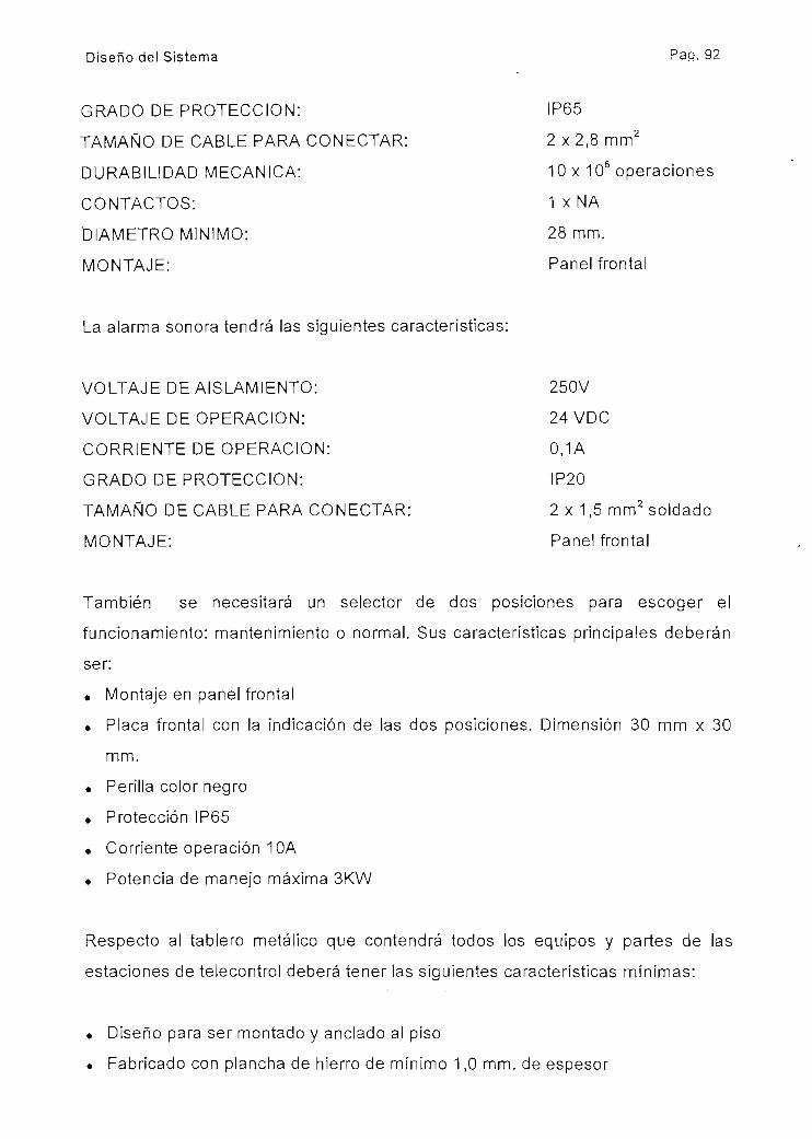
Diseño del Sistema Pap. 92
GRADO DE PROTECCIÓN:
TAMAÑO DE CABLE PARA CONECTAR:
DURABILIDAD MECÁNICA:
CONTACTOS:
DIÁMETRO MÍNIMO:
MONTAJE:
IP65
2 x2 ,8 mm2
10 x 106 operaciones
1 xNA
28 mm.
Panel frontal
La alarma sonora tendrá las siguientes características:
VOLTAJE DE AISLAMIENTO:
VOLTAJE DE OPERACIÓN:
CORRIENTE DE OPERACIÓN:
GRADO DE PROTECCIÓN:
TAMAÑO DE CABLE PARA CONECTAR:
MONTAJE:
250V
24VDC
0.1A
IP20
2 x 1,5 mm2 soldado
Panel frontal
También se necesitará un selector de dos posiciones para escoger el
funcionamiento: mantenimiento o normal. Sus características principales deberán
ser:
• Montaje en panel frontal
• Placa frontal con la indicación de las dos posiciones. Dimensión 30 mm x 30
mm.
• Perilla color negro
• Protección IP65
• Corriente operación 10A
• Potencia de manejo máxima 3KW
Respecto a! tablero metálico que contendrá todos los equipos y partes de las
estaciones de telecontrol deberá tener las siguientes características mínimas:
Diseño para ser montado y anclado al piso
Fabricado con plancha de hierro de mínimo 1,0 mm. de espesor
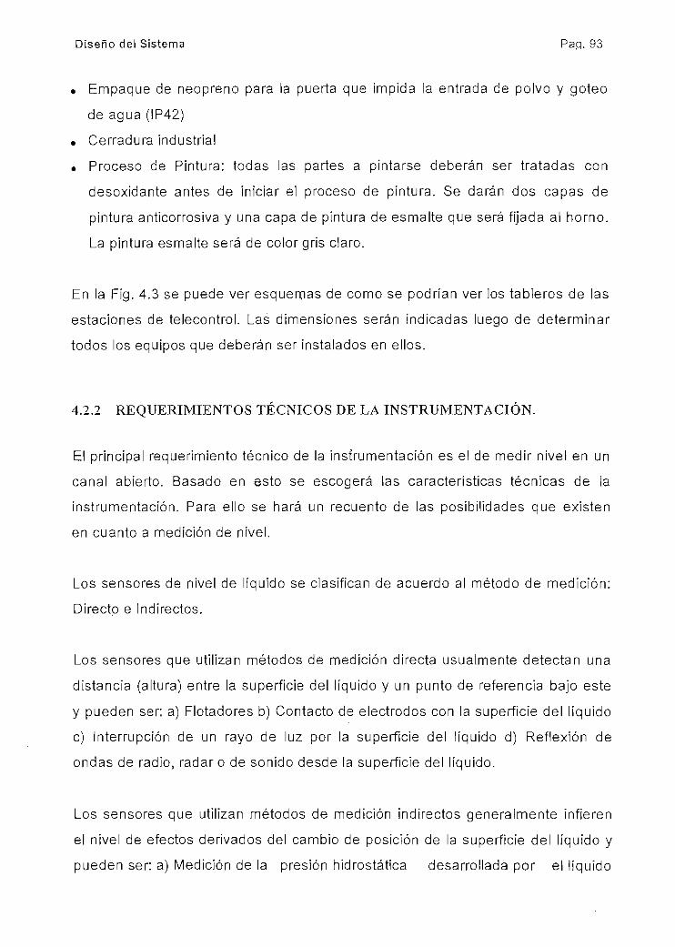
Diseño del Sistema Pap. 93
• Empaque de neopreno para la puerta que impida la entrada de polvo y goteo
de agua (IP42)
. Cerradura industrial
• Proceso de Pintura: todas las partes a pintarse deberán ser tratadas con
desoxidante antes de iniciar el proceso de pintura. Se darán dos capas de
pintura anticorrosiva y una capa de pintura de esmalte que será fijada al horno.
La pintura esmalte será de color gris claro.
En la Fig. 4.3 se puede ver esquemas de como se podrían ver los tableros de las
estaciones de telecontrol. Las dimensiones serán indicadas luego de determinar
todos los equipos que deberán ser instalados en ellos.
4.2.2 REQUERIMIENTOS TÉCNICOS DE LA INSTRUMENTACIÓN.
El principal requerimiento técnico de la instrumentación es el de medir nivel en un
canal abierto. Basado en esto se escogerá las características técnicas de la
instrumentación. Para ello se hará un recuento de las posibilidades que existen
en cuanto a medición de nivel.
Los sensores de nivel de líquido se clasifican de acuerdo al método de medición:
Directo e Indirectos.
Los sensores que utilizan métodos de medición directa usualmente detectan una
distancia (altura) entre la superficie del líquido y un punto de referencia bajo este
y pueden ser; a) Flotadores b) Contacto de electrodos con la superficie del líquido
c) Interrupción de un rayo de luz por la superficie del líquido d) Reflexión de
ondas de radio, radar o de sonido desde ¡a superficie del líquido.
Los sensores que utilizan métodos de medición indirectos generalmente infieren
el nivel de efectos derivados del cambio de posición de la superficie del líquido y
pueden ser: a) Medición de la presión hidrostática desarrollada por el líquido
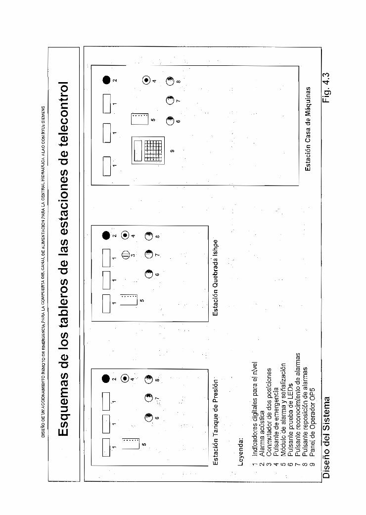
Js S
IEM
EN
S
Esq
uem
as d
e lo
s ta
bler
os d
e la
s es
taci
ones
de
tele
cont
rol
Est
ació
n T
anq
ue
de
Pre
sió
n
Ley
end
a:
1
Indi
cado
res
digi
tale
s pa
ra e
l niv
el2
A
larm
a a
cúst
ica
3 C
onm
utad
or d
e do
s po
sici
ones
4 P
ulsa
nte
de e
mer
genc
ia5
Mód
ulo
de a
larm
a y
seña
lizac
ión
6 P
ulsa
nte
prue
ba d
e LE
Ds
7
Pul
sant
e re
cono
cim
ient
o de
ala
rmas
8 P
ulsa
nte
repo
sici
ón d
e al
arm
as9
Pan
el d
e O
pera
dor
OP
5
3 4
6 7
Est
ació
n Q
ueb
rad
a Is
hpe
6 7
Est
ació
n C
asa
de
Máq
uin
as
Dis
eño
del
Sis
tem
aF
ig.4
.3

Diseño del Sistema Pa.q. 95
b) Sistemas eléctricos basados en los cuales se puede obtener el nivei del líquido
y que involucran propiedades físicas o eléctricas del líquido.
Como la medición del nivel en el canal requiere una medición continua, entonces
de los sensores con métodos directos tenemos a) y d) . De los sensores con
métodos indirectos a) y b).
Comercialmente entonces se tienen los siguientes tipos de sensores continuos de
nivel;
. FLOTADORES:
Este sistema utiliza esencialmente dispositivos mecánicos combinados con
elementos eléctricos-electrónicos. Por esta razón son poco utilizados a pesar
de su bajo costo. En nuestro caso definitivamente los descartaremos ya que
este tipo de sensor es utilizado únicamente donde la superficie del líquido no
tiene turbulencias o de lo contrario introducen muchos errores e imprecisiones
en la medición. Además sus elementos mecánicos requieren mucho
mantenimiento.
. ULTRASONIDO
Estos sensores utilizan el principio de reflexión de pulsos ultrasónicos en la
superficie del líquido. Para que la medición esté libre de errores y estable es
necesario que la superficie del líquido no tenga turbulencias ni variaciones
bruscas (olas). Así mismo falsos ecos, que redundan en errores en la
medición, se producen si entre la superficie del liquido y el emisor de los pulsos
de ultrasonido existe espuma, gran cantidad de polvo o humedad. En nuestro
canal ambas situaciones existen: turbulencias y polvo arrastrado por el viento.
Adicionalmente, el canal muchas veces arrastra ramas y animales muertos que
flotan en el agua o se atascan en la trayectoria del mismo. Esto haría que se
dificulte el tener mediciones de nivel confiables para nuestro sistema o que los
objetos arrastrados puedan arrancar la cabeza del sensor que se debe ubicar
sobre el canal. Para no tener los problemas mencionados se podría construir
un vaso comunicante junto al canal. Sin embargo, una obra de esa naturaleza

Diseño del Sistema " Pag. 96
sería muy difícil implementar en las paredes del canal que como sabemos
bordea las laderas de una loma y aún así, no solucionamos el problema del
polvo. Por lo tanto, este sensor tampoco es el adecuado para nuestra
aplicación.
. HIDROSTATICO
Se determina el nivel midiendo la presión hidrostática causada por el líquido.
Por lo tanto se requiere que el dispositivo sensor se lo instale en contacto con
el líquido a la altura de referencia. Existen de dos tipos; elemento sensor con
diafragma montado en una brida o conector y elemento sensor con diafragma
montado al final de un tubo flexible (llamados de suspensión). El primer tipo
tiene gran dificultad de instalación puesto que su brida o conector debería ser
colocado en la base del canal. El segundo puede ser depositado sobre el fondo
del canal pero el tubo debería ser sujetado al mismo con un anclaje especial.
Debido a las fuertes corrientes de agua y a los materiales arrastrados, el tubo
estaría sometido a grandes esfuerzos que probablemente lo romperían y
tendríamos grandes problemas de mantenimiento. Por este motivo lo
descartamos.
. RADAR
Básicamente este tipo de sensor opera bajo el principio de una antena que
emite microondas dirigidas hacia la superficie del líquido donde son reflejadas
hacia el sensor. Este instrumento es insensible al polvo y a fuertes turbulencias
de la superficie del líquido por lo que podría ser un buen candidato para
nuestra aplicación. Sin embargo los problemas de instalación que tiene, en
nuestro caso, el sensor ultrasónico se mantienen por lo que buscaremos otra
alternativa.
. RF ADMITANCIA/CAPACITANCIA
Este sensor utiliza como principio para medir el nivel, las propiedades eléctricas
de un condensador, donde el líquido hace las veces de dieléctrico, una punta de
prueba es uno de los electrodos y el otro es la pared de un recipiente por
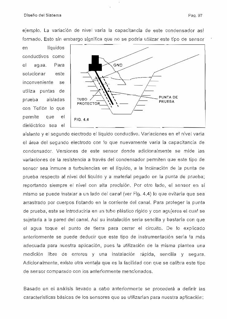
Diseno del Sistema Pag. 97
ejemplo. La variación de nivel varía la capacitancia de este condensador así
formado. Esto sin embargo significa que no se podría utilizar este tipo de sensor
en líquidos
conductivos como
el agua. Para
solucionar este
inconveniente se
utiliza puntas de
prueba aisladas
con Teflón lo que
permite que el
dieléctrico sea el
TUBOPROTECTOR
FIG.4.4
PUNTA DEPRUEBA
aislante y el segundo electrodo el líquido conductivo. Variaciones en el nivel varía
el área del-segundo electrodo con lo que nuevamente varía la capacitancia de
condensador. Versiones de este sensor donde adicionalmente se mide las
variaciones de la resistencia a través del condensador permiten que este tipo de
sensor sea inmune a turbulencias en el líquido, a la inclinación de la punta de
prueba respecto al nivel del líquido y a material pegado en la punta de prueba;
reportando siempre el nivel con alta precisión. Por otro lado, el sensor en si
mismo se puede instalar a un lado del canal (ver Fig. 4.4) lo que evitaría que sea
arrastrado por cuerpos flotando en la corriente del canal. Para proteger la punta
de prueba, esta se introduciría en un tubo plástico rígido y con agujeros el cual se
sujetaría a la pared del canal. Así su instalación sería sencilla y bastaría con que
el agua toque el punto de tierra para cerrar el circuito. De lo explicado
anteriormente se puede deducir que este tipo de instrumentación sería la más
adecuada para nuestra aplicación, pues la utilización de la misma plantea una
medición libre de errores y una instalación rápida, sencilla y segura.
Adicionalmente, existe otra ventaja que es la facilidad con que se calibra este tipo
de sensor comparado con los anteriormente mencionados.
Basado en el análisis llevado a cabo anteriormente se procederá a definir las
características básicas de los sensores que se utilizarían para nuestra aplicación:
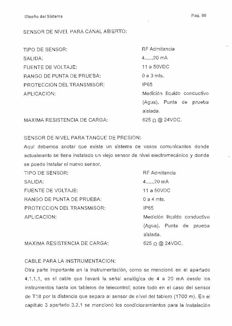
Diseño del Sistema Pap. 98
SENSOR DE NIVEL PARA CANAL ABIERTO:
TIPO DE SENSOR:
SALIDA:
FUENTE DE VOLTAJE:
RANGO DE PUNTA DE PRUEBA:
PROTECCIÓN DEL TRANSMISOR:
APLICACIÓN:
MÁXIMA RESISTENCIA DE CARGA:
RF Admitancia
4 20 mA
11 a 50VDC
O a 3 mts.
IP65
Medición líquido conductivo
(Agua). Punta de prueba
aislada,
625 n 24VDC.
SENSOR DE NIVEL PARA TANQUE DE PRESIÓN:
Aquí debemos anotar que existe un sistema de vasos comunicantes donde
actualmente se tiene instalado un viejo sensor de nivel electromecánico y donde
se puede instalar el nuevo sensor.
TIPO DE SENSOR:
SALIDA:
FUENTE DE VOLTAJE:
RANGO DE PUNTA DE PRUEBA:
PROTECCIÓN DEL TRANSMISOR:
APLICACIÓN:
MÁXIMA RESISTENCIA DE CARGA:
RF Admitancia
4......20 mA
11 a 50VDC
O a 4 mts.
IP65
Medición líquido conductivo
(Agua). Punta de prueba
aislada.
625 n 24VDC.
CABLE PARA LA INSTRUMENTACIÓN:
Otra parte importante en la instrumentación, como se mencionó en el apartado
4.1.1.1, es el cable que llevará la señal analógica de 4 a 20 mA desde los
instrumentos hasta los tableros de telecontrol; sobre todo en el caso del sensor
de T18 por la distancia que separa al sensor de nivel del tablero (1700 m). En el
capítulo 3 apartado 3.2.1 se mencionó los condicionamientos para la instalación

Diseño del Sistema Pag. 99
del cable de comunicación, dichos condicionamientos también se aplican a este
cable por lo debería ser con características para ser sumergido en el agua o
enterrado. En el caso del sensor ubicado en T18, adicionalmente se debe cuidar
la resistencia máxima de carga del transmisor de nivel ya que el cable tendrá
1700 m. como se dijo anteriormente;
La resistividad de un cable de cobre es de 1,7 x 10~8 medido a 20°C, entonces el
área mínima del cable será:
= (p* l)* i /(Vf-Vi n o p)
donde;
R= resistencia del cable, != longitud total del cable, p= resistividad, i= corriente
máxima del lazo, Vf= voltaje de fuente del lazo y Vmop= voltaje mínimo con el que
trabaja el transmisor del sensor de canal abierto.
A= (1,7 x10'ü*2*1700)*20 x10'J/(24- 11)= 8,8923 x 10'am¿ =0,088923 mm"
Por seguridad se tomará:
A= 4*8,8923 x 10'9 m2 = 35,569 x 10'8 m2 = 701,9 circular mils
Esto corresponde a un cable menor a 21 AWG. Nótese que no se tomó en cuenta
la resistencia de entrada de la tarjeta analógica (31,5 Q) porque su valor es
pequeño comparado con el del cable. En la práctica y por segundad se utiliza
para este tipo de aplicaciones, cable multihilo de 18 AWG, por lo que las
características del cable serían:
CARACTERÍSTICAS: Cable multihilos recubiertos con
chaqueta aislante de PVC formando un
par trenzado, es decir 2 x 18 AWG
apantallado con cinta de Al, relleno de
gel y con cubierta protectora resistente

Diseño del Sistema Pa.q. 100
al agua y que garantice la
estanqueidad del cable.
RESISTENCIA DE AISLAMIENTO
ENTRE CABLES: 1,5 Go/Km
AISLAMIENTO ENTRE CABLES: 600 V
AISLAM. ENTRE CABLE Y
CUBIERTA PROTECTORA EXT.: 2000 V
TEMPERATURA DE
OPERACIÓN MÁXIMA: 60°C
PROTECCIÓN CONTRA SOBREVOLTAJES EN LA LINEA DE SEÑALES
ANALÓGICAS:
Las líneas de cable para llevar señales analógicas de medición son altamente
sensibles a sobrevoltajes inducidos o por contacto. El ejemplo más tipo de la
inducción de sobrevoltajes en las líneas son los rayos y de contacto directo por
fallas en e! aislamiento. En nuestro caso, el cable será tendido sumergido en el
agua de canal o enterrado en el borde del mismo y rodeando lomas; por lo que,
es una zona donde los rayos es el denominador común. Esto hace necesario e
imprescindible proteger las líneas contra sobrevoltajes producidos por estos
eventos para evitar daños en los instrumentos y en las tarjetas del PLC. Estos
dispositivos se encuentran ubicados en los cables y ubicados uno junto al
instrumento y y otro junto al PLC (ver Fig. 4.6).
TIPO: Para tecnología de dos hilos
VOLTAJE DE TRABAJO: 12 a 36 VDC
CORRIENTE MAX. DE TRABAJO: 1A
CARCAZA: Aluminio o plástico
PROTECCIÓN: IP65
CARACTERÍSTICAS: Limitación de voltaje a 50V o menos entre
líneas y entre línea y tierra.
Corriente de descarga de 2000A con una

Diseño del Sistema Pa.q. 101
onda de impulso de 20^s de duración.
Debe soportar 400 descargas de las
anteriormente indicadas.
4.2.3 REQUERIMIENTOS TÉCNICOS DEL MEDIO DE COMUNICACIÓN.
En el apartado 4.1.1.2 se determinó el tipo de tecnología de comunicación: Línea
dedicada y "half dúplex".
MODEM:
Para esto, el fabricante recomienda utilizar su modem MD100. Sus principales
características son:
• Módem para líneas dedicadas
• Velocidad de transmisión máxima 1200 bps.
• Comunicación en dos hilos "half dúplex" y "fu 11 dúplex" en cuatro hilos
• Pueden ser colocados en paralelo por seleccionar el modo "alta resistencia"
• Tipo de modulación: desplazamiento de frecuencia binaria (FSK)
• Banda de transmisión: 300Hz. a 3400Hz.
• Modulación: 1700Hz +-400Hz.
• Bajo consumo de corriente: 65 mA. 24VDC.
. LEDs de indicación: TxD, RxD y RTS
• Se comunica con el TIM011B a través de una interface V24 RS232 de 15 polos
• El modem convierte las señales digitales que llegan del TIM en señales
moduladas en frecuencia de voz para transmitir por el medio físico.
Este modem es un módulo separado de las estaciones ST100 o ST115 y se
instala montada en riel DIN de 35 mm. En comunicación de dos hilos esta
diseñado para telecontrol en modo "polling" y en cuatro hilos en modo "polling" y
"continuo". Para mayores datos mirar Apéndice
MEDIO FÍSICO DE TRASMISIÓN:
Como se indica en el apartado 3.2.1, uno de los principales requerimientos
técnicos del cable de dos hilos para la comunicación es que sea apto para

Diseño del Sistema Pag. 102
enterrar o sumergir en agua. Luego de varias consultas a diferentes fabricantes
de cable sobre un tipo de cable que cumpla con este requerimiento y que además
tenga la impedancia adecuada para la banda de transmisión y la distancia de
3000 m., podemos enumerar las características principales del cable a utilizarse
en esta aplicación:
CARACTERÍSTICAS: Cable mínimo de 2 hilos recubiertos
con chaqueta aislante de PVC,
apantallado con cinta de Al, relleno de
gel y con cubierta protectora
resistente al agua y que garantice la
estanqueidad de] cable.
RESISTENCIA MÁXIMA: 130 Q/Km
CAPACITANCIA ENTRE LOS HILOS: 52 nF/Km
RESISTENCIA DE AISLAMIENTO
ENTRE CABLES: 1,5 GQ/Km
AISLAMIENTO ENTRE CABLES: 500 V
AISLAM. ENTRE CABLE Y CUBIERTA
PROTECTORA EXT.: 2000 V
PROTECCIÓN CONTRA SOBREVOLTAJES EN LA LINEA TELEFÓNICA
DEDICADA:
Las líneas telefónicas con medio físico de cable son altamente sensibles a
sobrevoltajes inducidos o por contacto. El ejemplo más típico de la inducción de
sobrevoltajes en las líneas son los rayos y de contacto directo por fallas en el
aislamiento. -En nuestro caso, el cable será tendido sumergido en el agua de
canal o enterrado en el borde del mismo y rodeando lomas; por lo que, es una
zona donde los rayos es el denominador común. Esto hace necesario e
imprescindible proteger las líneas contra sobrevoltajes producidos por estos
eventos. El fabricante ha desarrollado un dispositivo para este efecto cuyo
nombre es LTOP. LTOP limita los sobrevoltajes y los voltajes de interferencia a
niveles no críticos. Adicionalmente dispone de un transformador de aislamiento

Diseno del Sistema Pag. 103
que provee aislamiento eléctrico lo que permite evitar que sobrevoltajes e
interferencias pasen a otras secciones de la línea (ver Fig. 4.5). Las más
importantes características son:
* Suprime los sobrevoltajes a valores aceptables antes de que alcancen la
electrónica que es la parte sensitiva de la comunicación.
• Segmenta eléctricamente la red de estaciones de telecontrol para evitar la
propagación de sobrevoltajes e interferencias.
• Limita los daños causados por sobrevoltajes al segmento afectado
* Todos los elementos de protección están montados sobre un módulo
enchufable de manera de poder reemplazarlo sin interrumpir la comunicación.
El concepto de protección comprende una combinación de componentes cuyas
funciones se complementan unas con otras:
1. Supresores de sobrevoltaje llenados de gas inerte (G1, G2)
2. Inductores para limitar las variaciones bruscas de corriente (L1, L2)
3. Varistores de metal óxido como protección fina (R1)
4. Transformador para aislamiento eléctrico (T1)
5. Diodo supresor (zener) para limitar el voltaje en el secundario del
transformador (V1)
Para mayor información mirar en el apéndice el catálogo.
LíneaTelefónica
G1
G2
L1 T1
R1
Modemo
V1
Fig. 4.5 L2
En la Fig. 4.6 se puede ver un diagrama de la conexión de los módems de las tres
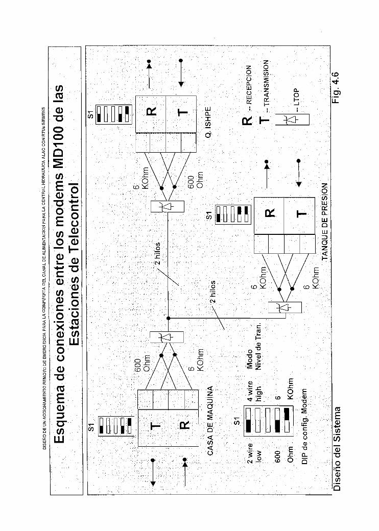
LJs
SIE
ME
NS
Esq
uem
a de
con
exio
nes
entr
e lo
s m
odem
s M
D10
0 de
las
Est
acio
nes
de T
elec
ontr
olS
1 R
600
Ohm
CA
SA
DE
MA
QU
INA
S1
2 w
ire
low
600
Ohm
i ¡
4 w
ire
Mod
ohig
h
Niv
el d
eT
ran
.
6 KO
hm
DIP
de
conf
ig.
Mod
em
2 hilo
s
2 hi
los
S1 R
600
Ohm
TA
NQ
UE
DE
PR
ES
IÓN
Q. I
SH
PE
R
-RE
CE
PC
IÓN
T
-TR
AN
SM
ISIÓ
N
« L
TOP
Dis
eño
del S
iste
ma
Fig
. 4.6

Diseño del Sistema Paq. 105
estaciones de telecontrol a la red telefónica de líneas dedicadas. Dado que la
estación de telecontrol de la Casa de Máquinas y la Ishpe se encuentran al final
de la red, su módem debe estar configurado en modo de baja resistencia (600 Q)
para la salida del transmisor (T) lo que determinará los extremos de la red y las
salidas del receptor (R) en alta impedancia (6 KQ). La estación de telecontrol del
Tanque de Presión se seleccionará en alta impedancia tanto para el transmisor
como para el receptor ya que se encuentra entre los extremos de la red,
4.2.4 DISEÑO DEL ACCIONAMIENTO MECÁNICO DE LA COMPUERTA.
El diseño del accionamiento de la compuerta se lo dejará a un ingeniero
mecánico, sin embargo se planteará los condicionamientos bajo los cuales
deberá realizar el diseño:
• De lo manifestado en el apartado 4.1.2, el sistema de accionamiento deberá
ser diseñado de manera que la compuerta sea liberada de sus orejas y caiga
empujada por la gravedad y guiada por los perfiles hasta cerrar el canal.
• Si bien el agua en el canal amortiguará la caída de la compuerta, el
accionamiento deberá tener un sistema adicional de amortiguamiento.
• De acuerdo a lo expresado en el apartado 4.1.1.4, el accionamiento será
neumático y la energía necesaria para su funcionamiento estará almacenada
en un compresor cuya capacidad será calculada adecuadamente. El
compresor dispondrá de alimentación alterna de 120VAC.
. El dispositivo de interface entre el sistema de telecontrol de Ishpe y el
accionamiento serán válvulas solenoides redundantes (2) conectadas en
paralelo.
• Una válvula de bola permitirá aislar el sistema
• Para elevar la compuerta se utilizará un dispositivo manual con el objetivo de
que el accionamiento no sea muy costoso. El mecanismo deberá tener
suficiente espacio para permitir el paso de un gancho estándar de tecle para la
elevación de la compuerta.

Diseño del Sistema Pag. 106
• El sistema de accionamiento deberá incluir además: carcasa protectora para
prevenir accidentes, cauchos para amortiguamiento de golpe de los sistemas
movibles y letreros de advertencia de peligro pintados en color amarillo con
fondo negro.
• Dos limitadores de carrera para detectar la posición de la compuerta: arriba o
abajo.
4.2.5 DISEÑO SISTEMA DE RESPALDO DE ENERGÍA PARA TABLEROS.
Para el diseño de la fuente de respaldo se tomará en cuenta las siguientes
consideraciones:
• La fuente de 24VDC, de cada unidad de telecontrol, alimenta la CPU de la
estación y la electrónica interna de las tarjetas periféricas (ver tablas de
configuración en apartado 4.2.1.1) con un consumo < 1,0 A. A propósito se ha
escogido una fuente de 5A. para que adicionalmente suministre corriente a la
restante circuitería de 24VDC como son: sensores, pulsantes, relés,
electroválvulas, alarma sonora, Panel Operador, módulo de alarmas y módem.
• Se dejará en bornes una toma de 110VAC 1A como toma auxiliar.
Estaciones Remotas Ishpe y Tanque de Balance:
ÍTEM DESCRIPCIÓN
1 Fuente de 24VDC 5A SITOP
2 Indicadores digitales x 3
3 Salida de 110VDC
TOTAL:
Factor de Seguridad de 50%
CONSUMO EN
AMPERIOS
1
0,3
1
2,3
3,5
Potencia Aparente ~ 3,5A x 110 V
S -385 VA.

Diseno del Sistema Pag. 107
El dispositivo de respaldo para la estación de ishpe, sea una UPS o una APS,
debe suministrar por lo menos 400VA y tener un banco de baterías que
suministre energía a carga nominal por 18 h.
Para la estación de Tanque de Balance debe ser de mínimo 400VA y 10 minutos
de respaldo.
Estacione Remota de Alao:
ÍTEM DESCRIPCIÓN
1 Fuente de 24VDC 5A SITOP
2 Indicadores digitales x 3
3 Salida de 110VDC
4 Fuente PS951
TOTAL;
Factor de Seguridad de 50%
CONSUMO EN
AMPERIOS
1
0,3
1
0,6
2,9
4,5
Potencia Aparente ~ 4,5A x 110 V
S ~ 495 VA.
El dispositivo de respaldo para la estación de Alao, sea una UPS o una APS,
debe suministrar por lo menos 500VA y tener un banco de baterías que
suministre energía a carga nominal por 10 minutos.
4.2.6 DIMENSIONES DE LOS TABLEROS.
TABLERO ESTACIÓN QUEBRADA ISHPE Y TANQUE DE PRESIÓN:
800 x 1.100x300 mm.

Diseño del Sistema Pap. 108
TABLERO ESTACIÓN CASA DE MAQUINAS:
800 x 2.200 x600 mm.**
* Las dimensiones han sido escogidas tomando en cuenta el tamaño de los
equipos SINAUT ST, dispositivos de protección, relés necesarios según diseño,
elementos a instalar en la puerta frontal y accesorios. Mirar catálogos de Siemens
y de otros equipos que podrían utilizarse en anexo.
** Este tablero tiene dimensiones sobredimensionada en alto y profundidad. El
motivo es que el tablero debe acoplarse a las dimensiones de los tableros
existentes en el cuarto de control de la casa de máquinas de la Central Alao.
4.2.7 FLUJOGRAMAS BÁSICOS DE LA PROGRAMACIÓN DE LAS RTUS.
Basándose en la información específica y de programación de las estaciones de
telecontrol, a continuación propondremos unos flujogramas muy básicos de las
partes principies que deberán contener los programas de los equipos de manera
que en un futuro se tenga una referencia.

Diseno del Sistema Pag. 109
4.2.7.1 Flujogramas de la Estación Maestra.

Diseño del Sistema Pag. 110
4.2.7.2 Flujogramas de la Estación de Tanque de Balance.

Diseño del Sistema Pag.111
4.2.7.3 Flujogramas de la Estación de Ishpe.

Diseno del Sistema Pag. 112
4.3 PLANOS.
En las páginas-siguientes se encuentra un conjunto de planos básicos con el
diseño de losJableros y sistemas.

CAPITULO V
CONCLUSIONES Y RECOMENDACIONES
Este capítulo no pretende ser un sumario de esta tesis sino más bien un
compendio de ideas inferidas a partir de este trabajo:
• Del análisis realizado en el Capítulo III se puede deducir que el problema
planteado es real y que necesita una solución urgente, puesto que es un
peligro latente para la población de Fúngala,
• En el mismo Capítulo 111, se plantea una solución que a lo largo de este
documento se ha demostrado que es técnicamente viable: Un sistema de
Telemetría y Telecontrol. Así mismo se plantean los requerimientos generales
y técnicos que deberían cumplir el sistema que surgiría de la implementación
de esta solución.
• En el Capítulo IV apartado 4.1 se plantea los criterios fundamentales que
sirvieron como directrices para el diseño del sistema de control y
monitorización: a) La técnica de comunicación maestro-esclavo b) Cuantas
estaciones se requieren y cuales son sus características c) Donde se colocará
la instrumentación y cual es su alcance d) La tecnología de' comunicación,
línea telefónica privada (dedicada) e) Criterios de seguridad, respaldo de
energía y tipo de accionamiento de la compuerta; y f) Requerimientos de los
usuarios.
. El diseño realizado en el Capítulo IV apartado 4.2 comprende tres puntos
importantes: a) Los tableros de las estaciones de telecontrol y telemetría b) El
medio de comunicación del sistema de telecontrol c) El accionamiento

Conclusiones y Recomendaciones Pa.q. 127
mecánico de la compuerta de Ishpe y d) El respaldo de energía.
• El sistema diseñado cumple con ser un sistema fundamentalmente de fácil
manejo tanto para personal de mantenimiento como para operadores, no
requiere de tareas complicadas de mantenimiento y el algoritmo que se
propone se ¡triplemente en el sistema de control de la compuerta (estación de
telecontrol de Ishpe) es simple lo que anticipa que será efectivo en la situación
de emergencia. El complemento para su efectividad será sin duda un
dispositivo para liberar la compuerta por gravedad que también sea simple,
efectivo y seguro. En el apéndice se adjunta esquemas de lo que podría ser el
sistema de accionamiento, el mismo que fue diseñado por un experto en
ingeniería mecánica.
• Todos los elementos del sistema que podría implementarse, con excepción del
accionamiento de la compuerta, quedan perfectamente definidos de manera
que basándose en la información contenida en este trabajo se pueda construir
el sistema. En cuanto al accionamiento de la compuerta, si bien se deja una
referencia en el Apéndice, se dejan establecidos los condicionamientos y
características que este debería cumplir con lo que será fácil para un experto
en estos temas diseñar el accionamiento requerido.
• Para completar la información del sistema diseñado se incluye como parte de
este trabajo los diagramas de flujo que plasman la filosofía de control a
implementarse en cada una de las estaciones de telecontrol del sistema con lo
que será fácil desarrollar los programas.
Las contribuciones que este trabajo hace se pueden enumerar a continuación:
• Poner de manifiesto la importancia que los sistemas de telemetría han
alcanzado en los diferentes sectores de la industria y en el mundo del control
de procesos.

Conclusiones y Recomendaciones Pag. 128
. Resaltar y demostrar que el diseño moderno de sistemas de control y
monitorización debe valerse de herramientas tales como los sistemas y
conocimientos que la tecnología y la ciencia moderna han puesto a nuestro
alcance. Estos sistemas han sido desarrollados con la contribución de muchos
recursos financieros y humanos y han sido probados suficientemente antes de
llegar a los usuarios.
» Se plantea una solución que se ha demostrado es técnicamente viable: Un
sistema de Telemetría y Telecontrol. Se definen los requerimientos generales y
técnicos que deberían cumplir el sistema.
• Todos los elementos del sistema quedan perfectamente definidos de manera
que basándose en la información contenida en este trabajo se pueda construir
el sistema.
• Se plantea un algoritmo de control para el accionamiento de la compuerta que
es una posible solución al problema planteado. Basado en ese algoritmo se
desarrolla el diseño de todo el sistema.
Finalmente se deja una ventana abierta a futuros investigadores para que hagan
sus contribuciones adicionales a este trabajo:
• Diseñar el accionamiento mecánico de la compuerta.
• Incorporar al diseño de la estación de telecontrol del Tanque de Presión el
sistema automático de limpieza de las rejillas de este tanque.
• Incorporar al diseño del sistema algunas de las tareas de control que requieren
ser automatizadas en la Central Alao con el objetivo de modernizar los
sistemas.

Conclusiones y Recomendaciones Pap. 129
Como recomendación se enumera la siguiente:
• Tener un gran cuidado al encargar el diseño del accionamiento de la
compuerta para que se acople al sistema diseñado en este trabajo, lo que
permitiría mantener una solución técnica viable.
El trabajo desarrollado en este documento está basado en un diseño realizado
por mi persona (ver certificado en Anexo F) para la construcción de un sistema
similar, el cual fue instalado y funciona satisfactoriamente. Sin embargo, se ha
incorporado mejoras en el diseño para perfeccionarlo, basándose en los
problemas y soluciones que se adoptaron en la implementación práctica del
proyecto. Estas mejoras principalmente se orientaron a incluir indicadores
digitales para lo tres niveles medidos en el Tablero de la Quebrada de Ishpe y
mejorar los dispositivos de protección contra sobretensiones en las líneas de
señal analógica de 4 a 20 mA.

BIBLIOGRAFÍA
1.- THE PRINCIPIES OF LEVEL MEASUREMENTGabor Vass, Octubre 2000, Princo Instruments Inc.,http:\www. princoinstruments.com
2.- SELECTING A LEVEL DEVICE BASED ON APPLICATION NEEDSParker S, 1999, Chemical Processing 1999 Fluid Flow Manual
3.- PROCESS INSTRUMENTS AND CONTROLS HANDBOOKConsidine Douglas, 1974, McGraw-Hill.
4.- LEVEL CONTROL CATALOG 1997-98Drexelbrook Engineering Company, 1997, Drexelbrook EngineeringCompany, http:\www.drexelbrook.com.
5.- VEGA LEVEL AND PRESSUREVega Grieshaber KG, 1999, Vega Grieshaber KG, http:\www.vega-g.de
6.- FUJI INSTRUMENTATION DATA SHEET BOOK 'Fuji Electric Instruments Co.Ltd., 1999, Fuji Electric Instruments Co.Ltd.,http:\www.fujielectric.co.jp
7.- OLFLEX HANDBOOKOlflex Cable, 1999, Olflex Cable.
8.- SINAUTLTOP: Line Transformer with Overvoltage ProtectionATD OG S, Noviembre 1998, Siemens AG.
9.- SIMATIC S5/PC/TI505 AUTOMATION SYSTEMS Catalog ST50AUT 97 Nbg M, 1997, Siemens AG, http:\www.aut.siemens.de
10.- SINAUTST1 MANUALANLA214F, Emisión A03 Octubre 1993, Siemens AG.
11.- CONFIGURARON AIDSATD OG2, Agosto 1998, Siemens AG.
12.- KONFIG1ATD OG2, Abril 1997, Siemens AG.
13.- SINAUT ST: Radio SystemsANLA72, Enero 1997, Siemens AG.

Bibliografía Pag. 131
14.- VERSATILE FSK-MODEM MD100 FOR STATION CONTROL ANDTELECONTROL UNITSANLA72, Enero 1997, Siemens AG.
15.- SINAUT ST1 Station Control System: System Overview.ANLA72, Enero 1997, Siemens AG.

ANEXOS

Anexo
A.- Presupuesto Referencial

Anexo Pag. 134
ÍTEM
1
2
3
4
5
CANT.
1
1
1
1
1
1
1
2
1
2000
3200
1
1
DESCRIPCIÓN
Estación Maestra Central AlaoTablero de Control completoincluyendo: PLC, protecciones,cableado, fuentes, etc.UPS 500 VA
Estación Remota Tanque dePresiónTablero de Control completoincluyendo: PLC, protecciones,cableado, fuentes, etc.UPS 500VA
Estación Remota QuebradaIshpeTablero de Control completoincluyendo: PLC, protecciones,cableado, fuentes, etc.UPS 500 VA con baterías derespaldo para 18 h. A carqa totalSistema de accionamientomecánico de la compuertaincluyendo el accionamiento propiode la compuerta y el compresor
InstrumentaciónSensor nivel canal abiertoSensor nivel Tanque de PresiónMetros de cable apantallado2xAWG18Metros de cable telefónicoapantallado de 6 conductores
ServiciosProgramación, supervisión deinstalación v puesta en marchaInstalación
TOTAL:
VAL. UNIT.USD.
17.145,10
1.100,00
7.983,52
1.100,00
6.138,64
3.000,00
6.757,70
3.000,002.000,00
2,53
0,93
3.000,00
5.000,00
VAL. TOTALUSD.
17.145,10
1.100,00
7.983,52
1.100,00
6.138,64
3.000,00
6.757,70
6.000.002.000.005.060,00
2.990,72
3.000,00
5.000,00
67.275.68
FUENTE: Presupuesto de construcción del sistema

Anexo Pag. 135
B.- Esquema de solución mecánica de la compuerta

1.
2 I
3 I
VIS
TA
S
UP
RIO
R
PIS
TÓ
N
NE
UM
ÁT
ICO
RIE
L
GU
IAB
AS
TID
OR
VIS
TA
LA
TE
RA
L
RIE
L
GU
IA
BR
AZ
OS
AB
AT
1B
LE
S
PA
SA
DO
R
DE
S
EG
UR
IDA
D
L
\E
D
E G
IRO
EJE
D
E
GIR
O —
BR
AZ
O
AB
AT
IBL
E
BA
ST
IDO
R
MU
ES
CA
VA
RIL
LA
S
DE
SU
JEC
IÓN
x-
HA
PC
O
DE
CO
MP
UE
RTA
ME
CA
NIS
MO
D
E L1
BR
ER
AC
IGN
. C
OM
PU
ER
TA
PLA
NA
D
ES
LIZ
AN
TE
Hodifo
clon |
ficha
|H
onbri|
*pro
bd
tubo
jo
ttiíf
to
05.0
7.01
RA
WO
CW
D»
T IÜ
DU
MO
COI
IRAL
AUU
)
AOXN
AUCN
IO C
OftJE
RTA
OCIA
UI5
KU
MC
OAU
TOC
AD
j!.
/a.
1KKo
ja
1
filJ_

7 I
3 I
_L
-VÁ
LV
UL
A
SO
BR
E
PR
ES
IÓN
MA
NÓ
ME
TRO
FIL
TR
O-R
EG
ULA
DO
R-L
UB
RIC
AD
OR
F K
I
EL
EC
TR
O-V
AL
VU
LA
PIS
TÓ
N
SIM
PLE
E
FE
CT
O
ACUMULADOR
Haí
ficíc
lon
[T
rtho
JKo
nbrf|
Apro
bó)
Dib
ujo
Oi.0
7.0l
RAM
ftOC
WD
ÚN
T Itl
flWO
Ü O
NIRA
L AU
O
COW
CRIA
•MJI
OCAO
19
/2Q
Hop

Anexo Pag. 138
C.- Tareas a Programar en los PLCs y definición de bits en elTráfico de Datos

Anexo Pag.
ACTIVIDADES A PROGRAMAR EN LOS PLCs PROYECTO EERSA
1.- TANQUE DE BALANCE:
. Medir nivel de tanque• Enviar nivel de tanque al maestro. Exhibir niveles en voltímetros• Chequear alarmas• Activar alarma sonora• Activar alarma sonora
2.- COMPUERTA ISHPE:
• Igual que ítem 1 con excepción de medir nivel de tanque y exhibir envoltímetros
. Medir niveles en Salida de Túnel e Ishpe.• Enviar niveles al maestro• Comparar niveles y comandar compuerta• Activar alarma sonora
3.- CENTRAL ALAO:
• Exhibir niveles enviados por RTUs en voltímetros• Chequear alarmas• Activar alarma sonora• Enviar niveles medidos en Ishpe a T. Balance. Exhibir datos en OP5• Activar relés en función del nivel (control de central)
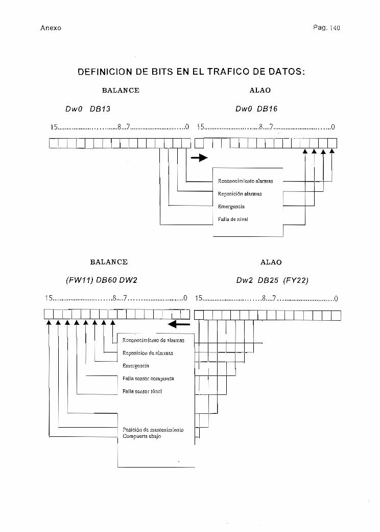
Anexo Pag. 140
DEFINICIÓN DE BITS EN EL TRAFICO DE DATOS:
BALANCE
DwO DB13
15, ...S...7
ALAO
DwO DB16
Reconocimiento alarmas
Reposición alarmas
Emergencia
Falla de nivel
BALANCE
(FW11) DB60 DW2
15 S....7
A Jk. Ai A Ai.
ALAO
Dw2 DB25 (FY22)
.0 15 S....7
Reconocimiento de alarmas
Reposición de alarmas
Emergencia
Falla sensor compuerta
Falla sensor túnel
Posición de mantenimientoCompuerta abajo

Anexo Pag.141
15.
ISHPE
DwO DB13
8...?.... .0 15.
ALAO
DwO DB11
S....7.....
A A A
ISHPE
(FW12) DB61 DW1
15.. S....7
Reconocimiento dealarmasReposición de alarmasEmergencia
Normal/MantenimientoOP5Falla sensor balance
Normal/Man-tenimientoReconocimien-to alarmaReposiciónalarma
Emergencia
CompuertaarribaCompuertaabajoFalla sensorcompuertaFalla sensortúnelPosiciónmantenimiento
ALAO
Dw1 DB26 (FY18)
.0 15 S...7

Anexo Pag. 142
BALANCE
DwO DB60
15.
Dw1 DB60
15 S...7.
ALAO
DwO DB25 (Nivel Túnel)
.0 15 .....S...7 O
Dw1 DB25 (Nivel Ishpel)
O 15....... ...S...7 ........................O
Fw40 (Nivel T.Balance) DwO DB15 (Nivel Ishpel)
15 S...7 O 15 S...7..... ........O

Anexo Pag. 143
ISHPE
DwO DB61
15............... ,...8...7.
ALAO
DwO DB26 (Valor Inicial dN)
.0 15 8..7 O
Fw42 (Nivel Salida Túnel)
15 S...7 .....O 15
DwO DB10
Fw44 (Nivel Ishpe)
15 S...7 O 15
Dw1 DB10

Anexo Pag. 144
DEFINICIÓN DE BITS FLAGS
15
Fw65 (FY66)
S...7 ..O
Simpor.
Rotura hilo S.N.l
Desborde margen S.N.l
Rotura hilo S.N.2
Desborde margen S.N.2
Bloqueo alarma sonora yLEDs titilandoIndicas! hay alguna falla
Marca de acuse recibo
Marca reseteo fallas
Marca de emergenciaMarcanormal/mantenimientoCompuerta arriba
Compuerta abajo
15
Fw67 (FY68)
S...7
A A A A A A

Anexo Pag. 145
N.Mínimo
N.Máximo
Estado mantenimiento
Falla comunicación
Compuerta abajo
Falla sensor nivel BalanceFalla sensor nivel Ishpe
Falla sensor nivel Túnel
15.
Fw63 (FY64)
,. S...7
VA A A

Anexo Pag. 146
D.- Hojas de Datos del Sistema Sinaut

SIEMENS
Your PartnerforTelemetry and SCADA Systems
SINAUT LSXUNIX-based SCADA System

SINAUT LSXUNIX-basedSCADA System
i Reliable supply of prívateand industrial consumerswiíh drinking v/ater,disíricí heating, gas andelectriciíy via branchednetworks
i Sewage disposal viapipeline networks
i Sewage purification ¡níreatment plañís
i Remóte monitoring ofsewage equipment
i Economical transport ofoil and oil producís viapipelines
i Remote monitoring ofwind and solar powerpiants
• Control and supervisiónof telecommunicationand traffic control ¡nstalla-tions
- (hese íasks require re-liable systems and com-ponents to enable fault-freeoperaíion, for boíh the localárea and remote regions.
SINAUT* (Siemens networkajjtomaíion) is suited forthe auíomation of small,médium and large net-works and plañís. Seam-less iníegration of standardcomponents - SIMATIC*S5 programmable logiccontrollers, SINAUT ST1síaíion control systems,SINAUT LSX supervisor/system over U\N's andWAN's (local and wide áreanetworks) - provides com-plete solutions for networkautomation.
For médium to large net-works, SINAUT LSX fulfillsnot only the highest de-mands placed on a SCADA(supervisen/ control anddata acquisition) sysíem,but includes also íhe in-dustry specific functionsrequired for water/wastewater, pipeline and supplynetwork applications.
Front page pictura:
TTie SINAUT LSX network controlsystem of the Marchfeld canal inAustria simultaneously processes¿OGO measured valúes.
Automaíion of v/ater plants, waste v/ater plants, pipelines and supply networks
2

SÍNAUT LSXCharacterist ics and Standards
SINAUT LSX is futuraoriented due to its staíe oííhe art sysíem archítectureand full compliance with in-ternaíiona! Standards.
SINAUT LSX ¡scharacter-ized by features such as:
• Adaptable ío market andcustomer requirements
• Can be used on work-stations; PCs and X-terminals
• Distribuíed concept with.respect to hardware,functions and datastorage
i System availability can beimplemented according tocustorner requiremenis,with hoí-standby systemavailable as standard.
i Compiles with iníerna-tional síandards
- Hardware:RISC processors
- Operating system:UNIX system V, reléase 4
- Programminglanguage: ANSÍ C
- Data storage:Relaíional daíabankRDBMS with SQLinter-face
- Communication:Ethernet IEEE 802.3(ISO/OSI standard,TCP/IP)
- User interíace:X-Windows and OSF-Motif
i Uniform man-machineinteríace
i Consistent configuring ofall data and parameters
i Rationalizaíion of engin-eering by object orienta-tion
l Full-graphic visualizationwith window techniques,zooming and declutíering
• Online parameterizationpossible
• Protection against un-authorized access
• Open interíaces for usersoftware
Due ío the distributedarchítecture and use ofstandardized hardware andsoftware platíorms, thesysíem can be extended ortransported ío meet fuíurerequirements. The usersinvestment is protecíedand the lifespan of thesystems extended.
Full-graphic visualization with window techniques

SINAUT LSXWith Distributed System Architecture
Modern SCADA systemsemploy powerful process-ing and data storage sys-tems, user interfaces withwíndow techniques andfull-graphic visualizationsystems. Hardv/are per-formance ¡s required whichcan no íonger be providedby centralizad sysíems.Distribution of functionsand data over severa! hard-ware components is ne-cessar^. Paralle! processingresults in an almost un-Ümrted performance andalso increases the avail-ability.
All functions are divided iníhe SINAUT LSX into threelevéis:
• The automation leve!
This incorporates severalprogrammable logic con-trollers and síation controlunits. Standard functionblocks (ASX) handle localmoniíoring and controltasks in real-time mode.Data, process síates andprocessing parameters areassigned a time síampwhen changes take place,and are applied acycllcallyto the respective área iníhe control room.
• The área level
Objecí orientad data areacquired, collaíed depend-ing on type, time stampedand are then available forfurther processing accord-ing to área. These funct-ions can be executed local-ly ¡n the área computer or
distributed arnongst furthercomputer systems. Forexample, filing and para-meterizatíon data are trans-ferred to a storage com-puíer, and programs withcomplex arithmetic ío anoptimízaíion computer.
• The dialog level
Dialog computers are usedto opérate and monitor theprocess. The man-machíneiníerface can be a worksta-tion, PC or X~terminalbased allowing single ormufti user configuraíions.
Powerful bus systems linkthe automation level to theárea level and íhe árealevel ío the dialog level. It ispossible ío link the processand dialog buses sincecommunicaíion ai all levéisis according to the Ethernetprincipie CSMA/CD, ISO/OSI standard 802.3.
Data base and functionalitycan be freely disiribuíedand extended across sev-eral áreas and computersaccording to application re-quirements. The LSX entrylevel comprises a singleárea cornpuíer coupled viabus to a programmablelogic controller.
Modular phased expansiónup to a mulíi-area systemwith redundancy of systemcomponents is a funda-mental part of the systemdesign philosophy.
Dísíributed sysíem strucíure
Dialog levet
Area leve!
Process bus
Automaíionlevel Ptogrammable
logre controllersPfograrnmable¡ogíc controllers
Local síations Teleconírol stations

SINAUT LSXThe Software Layer Model
SINAUT LSX ¡s designedso that ií can be opiimallymatched to dífferent re-quíremenís. This is achivedon the one hand by iís dis-íribuied architecture andselecíable availability, andon the other by implemen-ting íhe software accordingto a (ayer model.
The firsí layer, comprisingoperaíing system, datahandling system, graphicprocessor interface andcommunication sen/ices,shíelds higher layers fromíhe detalls of the hardwareplatform. As this layer ¡sbased entirely on Interna-tional standards, hardwareplatform independence ¡sachieved - allowing com-monly available PC's orworkstations ío be used.
The second layer com-prises software tools used
-to design, configure, para-meterize, test and diagnosethe run time system. Stand-ard industrial producís arealso used here and tailoredfor SCADA applicaíions.
Layer three provides LSXcore functions, this is inde-pendent of industry, butcontains the SCADA basefunctionality for;
• Process coupllng, objectprocessing and archiving
• Full-graphical operating,monitoring and eventsignalling sysíem
• Redundancy, communi-cation and parameteriza-tion
The core functionality canbe extended:
i Sequential control forautomatic output of com-mands and setpoints
i Data import/export inter-face for íhe transfer ofdata to/from further par-ticipants in the network
• Full-graphic processvisualization in the formof displays, curves, busi-ness graphics
Industry specific funcíional-¡ty is provided in the fourthlayer connecíed to the thirdlayer via a standardizedopen iníerface.
SIMAUT LSX software layer model
SINAUT LSX
Corrí municationa ISO/OSt a NFSDTCP/1P 0X11.3
€'"cí•acu•ocO)Ic(Ua_O
GJ
en
- X-terminals
Mainiéfianc training,--• ";*'¿ ^ '~v>-:&Cif n«í -i,f" " - ' 51'., ; • * . r^--J---f *i- , ; ¡C^?•!•>**.• •*,- ..^í- % * * • • • "^-i1* ".••..-í-v****^ -E»-«*?-*•• »• • - -M

SINAUT LSXIndustry-specific Characterist ics
Process informaiion (e.g.pumps, sude and butlerflyvalves) is collated accord-ing to type and processedas so called "objects". Inorder to monitor and con-trol the plañís, all objectsare soríed according toideníical types and pro-cessed object-oriented.
The amount of signáis(nurnber of messages,measured valúes, countedvalúes, commands andsetpoints) and the asso-ciated processing íunctionsare defined once for every
type of object. The pro-cessing funcíions includeboth the automation level(ASX-íyp¡cal) as well asthe área and dialog levéis(LSX-íypical). The result isa Typicai" with a modelcharacter for all automationfunctions of this type ofobjecí.
The-typicai also defineshow this object is to be ac-cessed, monitored, visual-ized and parameterized.The individual parametersof a typical can be modifiedboth locally in the pro-
grammable logic controllerand cenírally in the controlcenter. A communicationsystem integrated in theLSX/ASX distributes íheseparameters to the correctprocessing point (data con-sistency).
The fourth layer of the soft-ware module comprises ¡n-dustry specific standard so-lutions for waíer/wastewater applications, pipe-lines and supply networks:
• Process coupling to thestandard function blocksASXof the automation level.
The standard functions canbe execuíed locaily in thecontrol center (LAN área)buí also in node stationsand substations (WANárea). The integrated com-munication system trans-ports data, statuses andparameters.
• Process simulation
Data telegrams can besimulated vía an import in-terface of the processcoupling, and the LSXfunctions can be íestedaccording ío áreas.
SINAUT LSX software modules
w
"J
LSX optíons
LSX basíc system
*PKícesG simulation¿-•7-2 - *
Evení-slgnalling/Information system
PrccesscouD-mg
Communicationsystem
•íf'í3*3y'• *•-•**• N-
--''i:'^ ASX coupling
1SO/OSI processcommunication
User interfaceOSF/Motif. X-Windows SQL relational databank
UNIX 5.4 operating system
CommunicationTCP/IP distribution

Demonstrations,Trainmg, Service
• Opíimizaíion of purchas-ing
Preveniion of purchasingpeaks by incorporation ofmeans ío cover máximumrequirements. Extrapolaronof purchasing and/or con-sumpíion valúes by diffe-rent methods (a messageis ouíput to warn of anapproaching limit violaíion).Constant determinaron ofpeak valué, demand ratecalculatíon and calculationof opíimum purchasing li-mit. Planning of means tocover máximum require-ments taking into accountvarious restricíions andwith selectable assignmentof prioriíies to the measu-res used to cover máxi-mum requirements (e.g.switching-off oí loads orswitching over to othersources of energy).
• Predíction
Calculation of expectedquantiíies by means of ad-aptiveprocedure ("learning"systems) on ihe basis of aspecific model predicíion.Various daily characteristicsand weather influences aretaken inío account.
• Coníract optimization
Purchasing coníracts withvarious suppliers are usedoptirnally by the división ofpurchased quantities be-íween the contracts. Thecalculaíion proceduresmoothens the parchasestaking into account contrac-tural and technical restric-tions.
• Network control
The control of the networkin normal mode is simpli-fied by a íhree-stage auto-maíic system:
• Specification of quantitiesfor purchasing staíions
• Pressure inputsforceríainpoints of the network
• Pressure synchronization/equilibrium at selectedpoinís of the network
• Maintenance and repair
Monitoring of íhe operatingand síandsíill times of equip-ment, checking of switchingfrequencies. Output of re-ports for required mainíen-ance and forcompletedmaintenance.
• Fault analysis and gene-ration of reporís wiíh stor-ing, logging and display ofload curves. This sewageplant specific function ful-filis all requirements of ATVH260 (ATV = Germán Sew-age Treatmení Associaíion).
• Leak checks
Balancing of input and out-put quantiíies, and moniíor-ing of pressure responses.
Further índustry specificfunctions can be integratedvia the standardizad, open-ended interfaces. Thesefunctions can be installedlocally on an área computeror parallel on a sepárateoptimization computer de-pending on the free capac-ity available. A telegraminteríace of the LSX com-munication system enabíesthe access of all currentrr':asured valúes in theprocess image and históri-ca! valúes in the long-terrnfile. Newly calculated val-úes can again be stored inthe process image andlonc >rm file.
Project specific functionsare thus integrated into thesystem environment of íheLSX such that ths LSX fea-tures also apply to thesefunctions, e.g. the faciliíiesfor distributed implementa-tion, the uniform operatingfacilities and the consist-ency throughout the sys-íem;
On our demonstrationsysíem we can show youthe range of functions ofSINAUT LSX with al! hard-ware and software com-ponenis.
Two different networks canbe moniíored and con-trolled from two dialogstations using this system.Process simulaíion enablesthe dynamitwesponse tobe demonstrated andexamined via public corn-munication networks(Datex, telephone network)as well.
In addition to cusiomerdemonstrations, this systemalso serves for íhe trainingof our cusíomers wííhrespect to configuring andmaintenance tasks.
Customer configurationscan also be simulaíed onthe sysíem in order to ana-lyse adapíations or for fur-ther developments.
Our training ser/ices guar-anlee comprehensiva train-ing of customer personnel.The services provided byour distributed service cen-ters guarantee the highavailability of the ínsíalledsysíems.
SINAUT demonstraíion sysíem

SIEMENS
Compeíent Station and Network Control Technology
Telecontrol and Message Servicevia Trunk Radio

Telecontrol and Message Service via trunk radiowith the SINAUT ST1 station control system
The SINAUT1 STl station control systembased on SiMATIC5 55 now permita dataUansmission vía trunk radio m additionto WAN communication vía prívate andleased Unes or diailmg networks.
The trunk radio is a mobile radio serviceoffered by public and prívate companies.It combines the convenient performan-ce features similar to a mobile tele-phone wuh the tow charges of a com-pany radiotelephone. Voice and datacan be transmitted simultaneously inthe trunk radio necwork.
A sepárale radio channel is providedfor íhe voice transmission. The assign-ment of this channel is handled by theorganizational channel. The data trans-mission is always via the organizationalchannel. The transmission procedureis similar to packet switchmg. Thevanous subscribers are sequentiallyassigned a time slot for data trans-mission in the organizational channel.Depending on ihe network loading,the typical transmission time for ashon message is 2 to 4 seconds. Thetrunk radio network is mainly suitablefor the sporadic transmission of smallto médium data quantities.
A special type of data transmission isthe "Message Service". This permitsíhe transmission of messages with upto 100 atphanumeric characters to calisiandby or maintenance personnel.The source of íhe message can be anytelecontrol siation or masíer station(SINAUT STl 15, ST135, ST155) in thetrunk radio network. The output is onthe display of a handy or a handsetwhich can optionally be connected tothe trunk radio terminal equipment. Themessage can be acknowledged fromthe handy or handset.
Blockdiagram{examplej
Higrer-level control syslem
In addiíion to the publi^ suppíierDeTeMobil in Germany with iís net-work named "Chekker" there are alsonumerous prívate suppliers of trunkingsystems, some of which have combinadinto larger associations. The publicChekker network is oneníed accordíngto economic regions and thus coversspecific geographíc regions. The cover-age of the prívate networks is basedon entena defined by the respectivesuppíier. Trunk radio networks are alsoavailable m other European countnes.
. _ . _ _ . .
SINAUT STl master station
TIM 11C
*•
•.' ••«..,: •, - ^át^-,:-~--"~í>vi:-i;V'
1 Trunk radio unit^
- 'STí&CTT '••,- J% : *V*
TiMOllC
SIWAUTSTl 00
^
'"-Ti
-'"i
•:' •¿a.'jit$Sí
ST
Trunk radio unit ; j
Ípyp^H
TIM 1 1 C
§¿ l
SINAUT115/ST135/ST155
.'-.- . "•-„ Process. *Pfv:. r"'«lt¿>-
The most important features
• Use in transpon and supply networksfor drinking water, district heating, gasand electric energy, in disposal net-works for wasíe water and in otherwidely-branched processes andsystems
• Radio link for simultaneous transmis-sion of data and voice in the completetrunk radio región with the possibilityqf transmission to adjacent regions
• In addition to telecontrol functionsand Message Service, a SINAUT STlstation control unit can also carry outopen-Ioop control, c!osed-loopcontrol and processmg functions
• Data communicaüon on the organi-zational channel with the MAP27protocol envelope (Mooile AccessProtocol} into which the SINAUT STprotocol element >s enclosed
• Protection of asynchronousSINAUT ST protocol with Hammingdistance of d=4 using CRC (cyclicredundancy check) with FT2 messageformal according to IEC 870-5
.•4•-'•vi
- 1•J• Design of complete control systems
also in conjunction with other dedt-cated and dialling networks us.ngthe SINAUT STlOO to ST155 sta'.cncontrol units
• Use in redundant and fault-toie^antsystems
• Up to 250 SINAUT STl stations canbe connected to one SINAUT Silmaster siation
• A TIM telecontrol interface rnodüe nthe master station should process amáximum of 10 trunk radio stattons íoguarantee good reachability; up to15 TIMs can be used in the mastersiation
• Transmission speed up io 9600bits/s, dúplex
• A telecontrol station can communi-cate with up to 8 master stetions ¡nthe trunk radio network.

The SINAUT ST1 units fortrunk radio
See Cataiog SIMATIC ST50 for input/output modules
SINAUT STIOOstation controf unltwjth-CPU 103 •/ *v' ^# ; V ,.]v;ith TIM 011C telecontrol mterface module for trunk radio, MAP 27/SINAUT 5T protocol, mcluding EPROM submodule 375-A2 06kByieL-,Hwith connecting cable (2.5 m) oetween TIM 011C and trunk radio unit, wuh message/call number memory (52 kByte), mounting railsIMS 710 (530 mm). for cannection to 24 V DC or to 115/230 V AC. 50/60 Hz vía PS 931 oower supply or vía PE buf fer unit. 4) 11)
24VDC
115/230 VAC with
PS931 (2A)
11 5/230 VAC withP£3buHeruni| (6 5 Ah)
without nstallat'on 1 for ,vail mount.ng enclosure/cabinetwith .nstallation/standard function test
without .nstallationwuh ¡nstallation/standard function test
wuh instailation/standard function test
for wall mounting erclosure/cabinetinstal'ed m v/all enclosure WG 01 1)mstai ed m wall enclosure WG 02 1)3}for wall mo'jnt.nq enclosure/cabinetfor .valí mounting enclosure/cabinetir-stai'ed m //all enclosure WG 01 1)mstalied .n wall enclosure WG 02 1) 3)mstaüed m wall enclosure WG 01P 1) 2)«rstal'ed m wail enclosure WG 02P 1) 2) 3]
33337777
ABEFABcF
7 |G7 H
with mterrupt bus unit ABM 700 C Icrimp cannection) for any module (TIM. 70 r 5} _p_with bus unit BM 700 C (cnmp connection) for any module (TIM, I/O) _1_with mterrupt bus unil ABM 700 S (screw connecnan) for any module (TIM. I/O) 5) dwith bus unit 3M 700 S (screw connection) for any module |TIM. I/O) 5withoui SIMATIC S5-100U system manualwuh SIMATIC S5-100U system manual, Germán versiónwith SIMATIC S5-100U svstem manual. English versión
rol
with TIM 1 1C Telecontrol mterface me132 kByte), with casmg, wuh conreen¡ncluding assembly/mstallation and SK
Power supoly modulePS 3 with bufferbauery for RAM(notforTIM)wtthouiexpansión unit
wuh expansiónunit ER 701-1
• .>ayj;u;*i&j r?fe.i5íi£!
dule for trunk radio. MAP 27/SINAUÍ 5I~ protocol. wuh message/call number memory 6NH1152- *ng caoie c¿ b mj oetween nM i IL ana trunn radio unit, witn mounung racK CM /uu-¿,ndard function test
24VDC (-t-20 ..+30 VI, output 5 V/7 A. witrout fan 6) Yj24VOC(-t-20...~30V), output 5 V/15 A. wth fan _3j115V/230 VAC. output 5 V/7 A, wilhout fan 6) jj115V/230VAC. output 5 V/15 A. with fan 7for wall moumed enclosure or caomet | Ainsialled in wall enclosure WG 1 1 (HxWxD = 760x600x350 mm) 1)7) _B_mstalied in wall enclosure WG 1 2 (HxWxQ = 1 200x600x400 mm) 1)8) Cwith mterface module IM 305, for wall/cabinet mstallation 9) f_with interface module IM 305. instaHed r .valí enclosure WG 12 1) 9) .Gwith 2 IM 306, SL 705-0. for wall/caoiret -ns:a lation 1 0) iZIwilh2IM306. SL 705-0, installea n wa I enclosure WG 12 1) 10) JL
• wuh CPU 941 incl. EPROMmemory module 375-A2 (16 Kbytes). with. rMe'-a- RAM (2 Kbytes] 11) ~^~]• with CPU 942 incl. EPROM memon/ module 375-A4 (32 Kbytes), with .«10." & RAM (10 Kbytes) 11) ~^~• with CPU 943/1 incl. EPROM memory module 375-A6 (64 Kbyles). with m'e-dl RAM (48 Kbyles) 11) 12) [Y• wuh CPU 943/2 incl. EPROM memory module 375-A6 (64 Kbytes], witn mie-nal RAM (48 Kbytes] 11)12) PJ• with CPU 944/1 mcl. EPROM memory module 375-A6 (64 Kbytes). witr n!e'-di R¿M (96 Kbytes) 11) 12) | <t
• wuh CPU 944/1 ,ncl. EPROM memory module 375-A7 (128 Kbytes). wu* -e»rai RAM (96 Kbytes) 1 1) 12) [£• wuh CPU 9<i4/2 -ncl. EPROM memory module 375-A6 [64 Kbytes). with n-'vaí 3AM (96 Kbytes) 11)12) [f~• wilh CPU 944/2 mcl EPROM memory module 375-A7 (128 Kbytes). w.i" • ---a' ^AM 196 Kbyles) 11)12) pTwithout SIMATIC S5-1 15U system manual 0with SIMATIC S5-115U system manual, Germán versión j twith SIMATIC S5-1 15U system manual, English versión \2~
Options for wall mounted enclosures
LAMP
SIFl BST-DOSE
Instailaiion of cabmet lamp mcl. fault signallmg Un the pianm.must be reserved to actívate ibe cabmet 'ampllns:ailatpon of a radio-mierference suporession filter Ireou reo;nsiaiiation of a socket mcl circutt breaker
g stage. a digital output
*o' ti^-t class B)
6NH1740-OAA01
6NH174O-OABOO6NH1740-OAA10
PUFF.BAT. Buffer Battery for CPU 103 Absolutely required when uSirg the CPU wuhoutEPROM 375-A2 memor1/ module, optional for use witn memory -r-cduie.
6ES5980-OMA11

-ÍV
v/'th f!M 11C teíecontrol -nterface module for trunk radio, MAP 27/SiNAUT ST protocol. wuh message/cail nurrbermemory '32 '<Byte), wuh connecung caols (2.5 m) ce'.ween T!M i 'C 3nd ;runk 'adío unu, «nclutimg assernbly/installation andstandard fundían test '3)
6NH1352-
Power supplyDC 24 V.
ba::ery 'or RAM!not 'or TIM)
Power suoolyAC 11 5/230 V,rrcl back-upbatiery for RAM
ínot 'or TiM)
output5V/18A
5 W4Q A
output5 V/i 8 A
cuíput5 V/40 A
without expansión unu ["y[A"wuh exparsion unU cG 183U DC. IM 300-3. IM 312-31. STL 760 14) 3 j ewuh exoansion unu EG 184U DC. ÍM 30Q-5C. IM 312-51 14) 3(0wuh exoansion unu EG 187U. IM 300-5C. ¡M 312-51 14) 3 Fwuhout exoansion unu 4 | Awuh expansión unit EG 183U DC, ¡M 300-3. IM 312-31. STL 760 14) [Jwuh expansión unu EG 134U DC. IM 300-5C. IM 312-51 14] J 4wun expansión jnit EG 187U. !M 300-5C, IM 312-51 Id] dwuhoul expans.on unu 7wuh expansión unU EG 133U AC, IM 300-3, IM 312-31, STL 760 14) 7wuh expansión unit EG 184U AC. IM 300-5C, .M 312-51 Id) 7wuh expansión unit EG 187U. 'M 300-5C. !M 312-51 14) | 7without expansión unit ¡ 8with expansión LJPII EG 183U AC. IM 300-3. IM 312-31. STL 760 14) QjFwuh expansión unit EG 1S4U AC. IM 300-5C. IM 312-51 Id] |_S_
CDFACOFAr
o"with exoansion unit EG 187U. !M 300-5C, IM 312-51 14] ' 8 ] F
• wun CPU 922. wuh memory cartí EPR 376-64 (64 Kbytes) wuh manual 135U/922 Germán151 wuh manual 135U/922 English
• w tn CPU 928, w th memory card EPR 376-64 (64 Kbytes) '.vitn manual 135U/928 Germán15) A-uh manual 135U/928 English
• w;thCPU 9288, wuh memory card EPR 376-64 (64 Kbytesl wuh manual 135U/928B Germán15) wuh "ianu3l 135U/928B English
• wun CPU 948-1 (640 Kbyies .ntern. RAM) wuh manual I55U/948 Germánand memorv card CL-EPR 374-51 2 (5 i 2 Kbytes) 1 5) 1 6) wnh manual 1 55U/948 English
i
• i
t
• 1
"bTFii22
Id• wun CPU 948-' ;640 Kbytes ntern. RAM) wuh manual 155U/948 Germán j_5_
and memon/card FL-EPR 374-1024 (1 Mbyte) 15) 16) wuh manual 155U/948 English "T• wuh CPU 948-2 (1664 Kbyies mtern. RAM] wuh manual 155U/948 Germán
ano memory card FL-EPR 374-5 12(512 Kbytes] 15) 16) wuh manual 1 55U/948 English• wuh CPU 948-2 (1664 Kbyr.es mtern. RAM) with manual 155U/948 Germán
and men-ory card FL-EPR 374-1024(1 Mbyte) 15) 16) with manual 155U/948 English
7
>2
1
2
1
2
1
21
7 ¡ 2
aa
1
*
The-
•TIM 011C
- -j.«^^y>^^5CLWwrír*vC..--,>'':' , *ífc:#.V33- ?; '<^*i
mS^^ff^^m^f^^^,^^Telecontrol interiace module for trunk radio for use m SINAUT STIOO 6NH1SCW-2BB01-3FBZ
• SL 701-5 BN Connectmg cable between TIM 01 IC and trunk radio unu. 2.5 m• TiM T1C Telecontrol imerface module for Irunk radio for use in SINAUT STl 15 ... ST155
6NH1701-5SN6NH1B02-OFA
- KAPSEL Casmg for T1.M1 IC (only required for SINAUT ST115) 6£S5491-OLB11• SL 701-5 AN Cannecnna cable between TIM 11C and trunk radio unit. 2.5 m 6NHT701-5AN• C-KIT *) Mouming ku fully assembled and wired on a mounting píate íor a master stationAelecontrol . 6NH984O-3CAOO
stauon for mstallation in a wall housíng door or standard cabinet, comprising:- Bosch KF Chip TD trunk radio unit without HA8 handy- Mounting set and holder for KF Chip TD- magnetic aerial with foot and cable (5 m)- extensión cable for aerial (4 m); aerial rod. 24- V olug and BNC plug- DC/DC converter 24 VDC/12 VDC, 2.1 A- Mounting píate (h x w x d = 250 x 400 x 60 mm)*) Other units and versions on request.
' C-KíT HA8 Mounting ku HAS as mouming kit above. but including HAS handy 6NH984O-3CA01
- PARA C Parametecization and commissioning support (on requeai)
•HF12T Bosch HF 1 2 T handy for Messaqe Service 6NH98AO-OCA02•TD1 SINAUT TD1 telecr-trol software
Contains the telec' ' 'oí sohware to genérate tre teiecortrol programs for the STIOO, STl 15, ST135and ST155 station control units as well as - from 'elease versión A07 onwards - the extensión forincorporation of the trunk radio (users of reléase versión A06 can receive an updatmg disketts on request)
Germán versiónEnglish versión
6NH1998-OAA166NH1998-OAA26
Key:Instailation >n wall mounted enclosures (re . -i forlimn ciass B, Qegree of piotecnon IP55I Tie .-.all-Tiounred enclost-res are delivered wnh buili-m STlstation control units and can oe equtoped opuonally^/ith a cabmet lamo, a fadio mieríerence suppfes-s.on f-Uei SlFI 3 and a mains sacket All cables afesnteided and gfcunced ai or.s point. GroundingaccofOing 10 VOE regs. Irec. 'ar 24 V d c. neg.g'oonaed networi:. pos grounded network requires3 c convencí!Cables are 'ed .n from belawThe .vail-enclasufes WG CIP'02P are connectedQ'-einally to i' 5/230 V AC. Techmcal data af thebuf*er wmi on 'equest'"el 2ro MS 710 siartíard secnonal ra-l and IM 315•nteraceUse ••? masier or outstat-on (noi as node station)-v churrea cuise acquismon aosoluielv 'equired as
6} When fetfohtti^g v/im a 'an. load up to 15 A. A fanis necessary ^r-en us.ng a CP Isee SIMATIC 551 orwhen mstail'ng <o a wail-rrounted enclosufe orcabmei.
7) Instailancn of expansión jmt oot passible later!SI Expansión ^nit can Ce addea 'ate/1
9) Fixed adíess-ng. AIS and AOs (max. •!] only mCR7QO-2
101 rfee adressif.g: ail /O modules can be pluged many slol
111 Tecnnical speC''ica:icr.s of CPU see page 5.121 The EPRCM -eniaces oari of :'"•& mtarnal RAM.
The secnon sf rre PAM ^/n>cn ts r-.o longeravaiiabie 'S tr.e SJme ¡engín as ir>e prograrn presenlen tre EPROM
131 Tecnr.!cai soec . quar.i.iy frarT-ewcrtí, equipmenlsee page 5 ^amer^Deí 'aoio soooression'eguladons wren .,mn c;ass 3 is 'equirgdOn rsauesi Síanuard caD.neis STS-1 ana ST53
l-i) For tecn. specs. for excans-on jn.rí jri .r-e''acemodules see ST50 catalog The cas^c j<* t '"e'facemodule 312-3/-5 conlams a O 5 ™ •;wn-.fr"j -aoiefor stacfced racks.
15) Tecnnical soecificanons of CP'J see oaqe 5 AnCPUs except CPU922 'eauíre 2 siots Tfe o-ant,almcludes Ihe systern man v ard :h» Ofogrammingguide of ihe CPU soeodea
16) The EPHOM replaces nart of 're "ife-M- =^AMThe seciton of ¡he RAiM wnicn 5 ~o cr-'T-' jva-'ícüs me same lengm as the prcgra^ C'-üc?-' -,n ¡"eEPROW
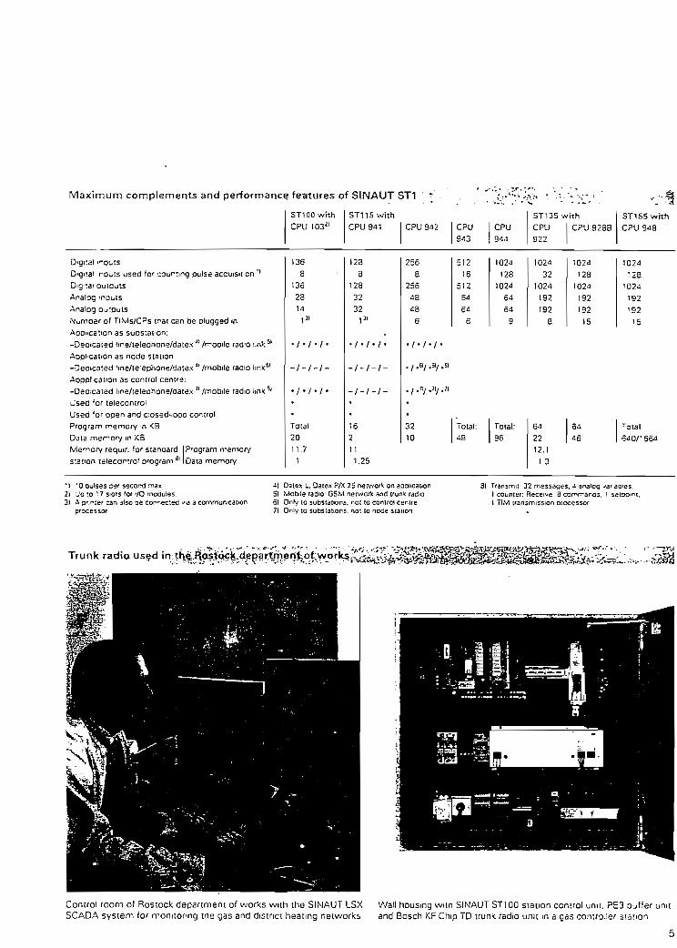
Máximum complements and performance features of SINAUT ST1
Digital «"oi-tsDigital routs used for cournng pulse accuisn.cn ''D-g'tai outputsAnalog ToutsAnalog Ou'putsNumrjer of TIMs/CPs ir-at can be plugged mAppncation as suDs:aE'on;
_ , . . , , •11 i i j i i SI— LJeoicated iire/teieonone/aa KX /fuune lauíu Mir,Aopt'Cation as ncde station-Decicated 'me/te'ephone/datex 4I /mobile radio 1mk=1
Apppl'catton as control cen^e
-Deacated Itne/teieorione/tíatex í] /mobile radio íink5'u'sed 'or telecontrolUsed 'or open and c:osed-íooo controlProgram r^emory 'H <B
Data merrory m <3
Memory requir. for stanoard
station ieiecon:rol o^ogram31
P'ogram rpemoryData memory
ST100 with
CPU 103¿l
136
3
136
23
14
I31
i i i
- / - / - / -
. / . / . / .
•
•
Total2011.7
1
ST115 with
CPU 941
1233
128
32
32
I31
.
/ / /
- / - / - / -
- / - / - / -
•
•
16
2
CPU 942
256
8
256
48
48
6
CPU
943
512
16512
64
6¿
6
CPU944
1024
128
1024
64
64
9
ST135 *
CPU
922
1024
32
1024
192
192
8
ith
CPU 928B
1024
1281024
192192
15
ST155 wHh
CPU 948
1024
:2S•024
192
1S2
15
/ / /
. i ,S1/ ,5lí .61
./.n/.«/.n•
32
10
Tptal:43
Total:96
11
1.25
64
22
64
46
rctal64 O/ '664
12.1
1 3
M 'O oulses ser seccmd ^ax21 Jo to ! 7 siois for i/O moaules.31 A 3';r*:er can a!so ae conceded vía a communicalion
processor
J) Dates L. Oatex P/X 25 nerv/orlc on aponcation5) Mabile radio: GSM ner^orfc and trun^ radio6) Only to substations. nat to control ceniie71 Only 10 subsiations. not lo node station
3) Tfansmif 32 messages, -í analog jar ames.1 counier: Receive 3 comrr'anos. ' 5etaoi"1 Ti.M iransmission processar
Trunk radia used
'.tissvít-ir1..
th£.E&^
Control room of Roslock depariment of works with the SINAUT LSXSCADA sysíem for rronitor-ng me gas and district heating neiworks
Wall housmg witn SINAUT ST100 station control umi. PE3 Djffer umtand Bosch KF Chip TD trunií radio unit m a gas cónico.;er síation

SIEMENS
Competent Station and Network Control Technology
Telecontrolviathe GSM Network

Station control system SINAUT ST1and the GSM network
The GSM network (Global System forMobife communication), known inGermany as the DI and D2 networkswas ¡ntroduced for digital, mobilevoice communication in 1993. and hasbeen rapidly developed since then.It has also been possible to use theGSM network for daia communicationsince the middle of 1994.
All European countries are obliged toesíablish GSM networks. Followingcomplete establishment, the GSMnetworks will be available everywhere,apart trom a few thinly-poputaíedregions. The chances are also verygood that the GSM standard will beimroduced to all parts of íhe world,apart from the USA and Japan whichuse other transmission standards.
There is more than one networkoperator in alrnost all (West} Europeancountries, and íhe strong competitionwill cerraíníy result in decreasingprices and fees.
Transmission on the GSM network issimilar to that on the telephonenetwork. Following estabüshrnení ofthe connection, a GSM telecontrolstation can exchange data with a GSMmasier station (mobile-to-mobile).
Systern exarfi"Mobile-tCh-T
Since there is a network transition tothe analog telephone network, a GSMtelecontrol station can also establish adata connection to a master stationconnected to the telephone network,e.g. via the MD125 dialling modem'1ímobile-to-fixed).
') MD125 approved so far in Germany,Switzerland and Austria.
The most important features
• Use in transport and supply net-works for drinking water, disíricíheating, gas and electric energy,in disposal networks for wastewater and in other widely-branchedprocesses and systems
• Design of complete control systemsvia GSM also in conjuncíion withoíher dedicated and dialling neí-works using the SINAUT ST100 toST155 station control uniís
• Use in redundaní and fault-tolerantsystems
• Up to 250 SINAUT STl stations canbe conrected to one SINAUT ST1maste :ation
' • v •. . ff??t ~'~'*yt^5' '."" ' - . • "• 'fí'*»¿' ?.r
••">, -¿r"1 '_«S ' i ^ • _^ ' -TSfiáí-L^A-r-c,;'^-"- Lf^c^r' - . • - - - .
Higher-Level control sysiem I
SINAUT ST'OO ST155
a /í£*_
Process
CP Communications processor
DSA Data service adapter
GSM Global system formobile commumcarion
TIM Telecontrol mterfacs modul
• A TIM telecontrol interface modulem the master station should processa máximum of 10 to 15 GSM tele-control stations to guarantee goodreachability; up to 15 TIMs can beused in the master station
• A telecontrol station can communí-cate with up to 8 master stations inthe GSM network
• The TIM 011 TEL (reléase versión6 and later) and TIM 11 TEL (reléase
. versión 14 and later) telecontrolinterface modules can be used forboth the telephone networx and theGSM network
• In addition to the telecontrol func-tions, a SINAUT* STl station controlunit can also carry out open-toopcontrol, closed-loop control andprocessing functions
• It is possible to build up "iñteü-ger-.t'outstations with charge-savingoperation
• Protection of asynchronousSINAUT ST protocol with Harnn->.rgdistance of d=4 using CRC (cyci.credundance check) with FT2 n~esssqeformaí according to IEC 870-5
• The S3 handy from Siemens canalso be used for data transmiss-on naddiíion to voice transmission icutnot simultaneously)
• Transmission rate currently uo ^o2400 bits/s (approval for up 10 3600bits/s expected shortly)
• Standby and maintenance perscnrelcan be called from any GSM teie-conírol station or master staucn(SINAUT ST115 toST155) us¡ngCITYRUF (¡n Germany only) The"Short Message Service" (SMS) «sprovided in the GSM network forthe transmission of alphanumencmessages and their output on thehandy display (SMS in prepararonfor SINAUT ST1J.
Front page picture:System example "Fixed-to-mobile" .v tiSINAUT ST115 telecontrol master stat.onand MD125 dialling modem as welt asSINAUT STlOO substation connectea :othe GSM network vía S3 handy artí DSAdata service adaptar

The SINAUT ST1 unitsforthe GSM network
See Catalog SIMATIC ST50 for mput/output modules
SINAUT ST100 station control unit with CPU 103.
mcl. EPROM memory module 375-A2 (16f<Bvie). mountmg raí! NS 710 1530 mm),for connection to 24 V DC or to 115/230 V AC. 50/60 Hz vía PS 931 power Supplyor va PE buffer jnt
Order Nos
6NH10O6-
4) 11)
24VDC
1 1 5/230 VAC withPS931 I2A)
11 5/230 VAC withPE3 buf'erunit
without mstallationwith irstallation/standard function tesi
wit^out installationwith mstallation/standard function test
with mstallation/standard function test
'or wall mountmq enclosure/cabinetfo' '.valí mountinq enclosure/cabmetirstaüed m wall enclosure WG 01 1).^staüetí m wall enclosure WG 02 1)3)for wall Toiinting enclosure/cabinet'or wail -^ountmq enclosure/cabinetmsta led m wall enclosure WG 01 1)ms:a:led m wall enclosure WG 02 1)3)ns-ailea n wall enciosure WG 01P 1)2)ns:alled .n wall enclosure WG 02P 1) 2) 3)
333377
ABEFA3
7 | E7 F
7 |G7|H
wth TIM 01 IB íor telephone or GSM network. SINAUT ST protocol. with n-.essage/cal! number memorv (52 !<Byte)* without modem for external V 25bis modem or connection to data ser/ice adapter• with GSM KITÍsee GSM network components)wnh mierrjpt bus unit ABM 700 C Icrtmp connection) for any module (T.M, I/O)with bus unn 3M 700 C (cnmp connection) for any module (TIM. I/O1v/ith ;nierrupt bus unn ABM 700 S (screw connection) for any module (T!M. i/O)with bus uru BM 700 S (screw connection) for any module (TIM. I/O)wthout SIMATIC' S5-100U system manualwith SIMATIC S5-100U system manual, Germán versiónwith SIMATIC S5-1QOU system manual. Enqlish versión
SINAUT 3X1-1 5 statiorí' p/itfój^o^^^^rv*^-.- •
for transmission. on telephone or GSM networks,with mountmg ráele CR 700-2. mcl. assembly/mstallationand standaro function test
~—~l
1.m
6NH1152-
Power suoply modulePS 3 with oufferbattery for RAMInotforTIM)withoutexpansión unit
with expansiónunilER 701-1
24 V DC <-t-20...-r30 V), output 5 V/7 A, without fan24 V DC [-20. . . f 30 V}, output 5 V/i 5 A, with fan1 15 V/230 V AC. output 5 V/7 A. wühout ían115V/230VAC, ouEput5V/15A. with fanfor wall mounted enclosure orcaometmsialled in wall enclosure WG 1 1 (HxWxD = 760x600x350 mm)¡nstalled ¡n v/all enclosure WG 12 iHxWxD = 1200x600x400 mm]with interface module IM 305, for waii/cac.net installattonwith interface module IM 305. msraHed n wall enclosure WG 12with 2 IM 306, SL 705-0, for wall/caomet mstallationwith 2 IM 306. SL 705-0. mstailed -o .-,ai' enclosure WG 1 2
61 pOAj
6) 5 .7 i
' A
1)7)
1)8)
9)1)9)
10)1) 10)
B
CF
•jJ
J<Jwith casing and telecontrol interface module• TIM 11 TEL (ST protocol) for telephone or GSM network. without mode-n 'or external V.25bis rnodem or connection to data service adapter• TIM 11 TEL (ST protocol) for GSM network with GSM-KIT (see GSM r^tworv components)• with CPU 9¿1 mcl. EPROM memory module 375-A2 (16 Kbytes). w *h• with CPU 942 mcl. EPROM memory module 375-A4 (32 Küyíes). w ti• with CPU 943/1 mcl. EPROM memory module 375-A6 (64 Kbytes). fi m• with CPU 943/2 mcl. EPROM memorv module 375-A6 (64 Kbvtesl. '.v:n• witn CPU 944/1 mcl. EPROM memory module 375-A6 (64 Kbytesl. A •>'• with CPU 944/1 mcl. EPROM memory module 375-A7 [123 Kbyiesl. A-• with CPU 944/2 incl. EPROM memory module 375-A6 (64 Kbytes). .v--• with CPU 944/2 mcl. EPROM memorv module 375-A7 (128 Kbvtesl .-.-'without SIMATIC S5-l 15U system manualwith SIMATIC S5-1 15U system manual. Germán versiónwilh SIMATIC S5-1 15U svstem manual. Enolish versión
•-terral RAM (2 Kbytes)r.-e^ai RAM [10 Kbytes)r-e-nal RAM [48 Kbytes)*-..?r^i RAM (48Kbvtes)• -^"-ai RAM (96 Kbytes)
- rvi-ai RAM (96 Kbytes)-<;.nd) RAM (96 Kbyies)
" r--e--ai RAM 196 Kbvtesl
11)11)11)12)11) 12)11) 12)11) 12)11) 12)11) 12)
H¡_2_
Ir[^f¥Li17
!1I1
1
1012
Options for Wall mounted Enclosures
LAMP Installatson of cabinet lamp mcl. fauit signalling (In the o'ar"irig stage, a digital outputTUSt be reserved to acnvate the cabmet 'amp)
6NH1740-OAA01
SIF1 B instailation of a radio-mierference suppression í-iter (feq-ireü 'or iimit ciass B)insta'lation oi a socket mcl. circun breaker
6NHT740-OABOOST-DOSEPUFF.BAT, Buffer Batter/ for CPU 103 Absoiuieiy required wnen uSirg the CPU without
EPROM 375-A2 rnemor/ module, opi-onai íor use wtih memory module.
6NH1740-OAA106ES5980-OMA11

Station control unH SINAÜT S.T135/ST15&. -
for transmission on teiepnone or GSM retwortcsircl assemaly/irstallatton and standard function test
6NH1352-13)
Power sucolyDC 2-1 Vncl back-'jDcatte1"1/ (c' ^AM
Power supplyAC 1 1 5/230 V.inct back-uoDatier/ for RAM(roí *or ~IM)
autput5V/18A
ouiput5 V/dO A
OuTpUt
5V/18A
outpui5 V/40 A
w¡thout expans.cn nitwth expansión uml EG 183U DC. IM 300-3. IM 312-31. STL 760 14)w.tn expansión unn EG 184U DC. IM 300-5C. M 312-51 14)with exoarsion urit EG 187U. IM 300-5C. IM 312-51 M)withojt expansión umtw.th exoansion unit SG 183U OC, IM 300-3. IM 312-31. STL 760 H]with expansión umt EG 184U DC. IM 3QQ-5C. IM 312-51 Id)wuh expansión uml EG 1B7U, 'M 300-SC. IM 312-51 14)withoui expansión umtwith expansión unit EG 1B3U AC. IM 300-3. IM 312-31. STL 760 14)with exoansion umt EG 184UAC. IM 300-5 C. IM 312-51 14)with expansión umt EG 187U. IM 300-5C, IM 312-51 14)without expansión umtwith expansión umt EG 183UAC. IM 300-3. IM 312-31. STL 760 14)with expansión unit EG 184UAC, IM 300-5C. IM 312-51 14)with exoansion umt EG 187U, IM 300-5C, IM 312-51 14)
3E3|C3 D3|r
4|A
a|Cd4
7
c
A
7 |C
7|D
7
3
F
A
1
1
. ' 11
8 |C | , 1
n-wi:i :e eccntrol .nterface module• TiM 1 1 TEL ¡ST protocci) for teiephone or GSM network. without mooem, for external V.25bis modem or connection to data service adapter• TiM 1 1 TEL (ST oratocoi) for GSM network with GSM-KIT (see GSM network components)• wjth CP'J 922. /vi?" memory cafd EPR 376-6¿ 154 .<byt.es)
15)• w.th CPU 928, with rremory card EPR 376-64 |64 Kbytes)
15)• wuh CPU 928B. wuh memory card EPR 376-64 164 Kbytes)
15)• wun CPU 948-1 1640 Kbyies mtern. RAM)
and memorv card FL-EPR 37^-51 2 15 12 Kbvtes) 15) 16)• with CPU 948-1 1640 Kbytes mtern. RAM)
a"d memory card FL-EPR 374-1 024 ( 1 Mbyte) 1 5) 1 6)• wuh CPU 948-2 11664 Kbytes mtern. RAM)
and memory card FL-EPR 374-5 12 (5 12 Kbytes) 15) 16)• with CPU 948-2 (1664 <bytes intern. RAM)
and memorv cara FL-EPR 374-1024 (1 Mbvte) 15) 16)
with manual 135U/922 Germánwuh manual 135U/922 Englishwitn manual 135U/928 Germánwith manual 135U/928 Englishwith manual 135U/928B Germánwuh manual 135U/928B English
- wilh manual 155U/943 Germánwith manual 155U/943 Enqlishwith manual 155U/948 Germánwith manual 155U/948 Enqlishwith manual 155U/948 Germánwith manual 155U/948 Englishv/ith manual 155U/948 Germánwuh manual 155U/948 Enqlish
DF 1
E-m1
0
0
hi2
1
2
1
21
| 2 | 2
£5
5
7
7
88
t
2
1
2
1
2
1
2
The
• T1M 011 TEL^•^f-W;:-:íí ^^¿H^^^ | ; .-
Telecontrol inierface module for teiephone and GSM networks. for use m S1NAUT ST100 6NH18W-28B01-3CB2• SL 70T-5 BN 2.5 m cable connectot between TIM 011 TEL and DSA• TIM 11 TEL Telecontrol interface module for teiephone and GSM netwgrks.fgr use in SIMAUT STll 5/135/155
6NH1701-SBN
•KAPSEL CasmgforTIM 11 lonly requiied for SINAUT STi 15)6NHia02-0£A__6ES5491^)LB11
• SL701-5 AN 2.5 m conneclmg cable betv^een TIM 11 TEL and DSA 6NH1701-5AN• GSM-KIT *) Mountmg ktt fully-assembled and wtred on a mounting píate for a master station/telecontrol station íor 6NH984O-3OAOO
installation m a wall housmg door or standard cabinet, comprising:- Vehicle mounting sel "Comfort" prepared for Siemens S3 handy- Dat sen/ice adapter- Cable- DC-/DC converter 24 V DC/12 V DC, 2.1 A- GSM network aerial (long), 3 dB gain- SAP plug íor connection of aerial to handy- Mountmg píate (h x w x d =240 x 350 x 65 mm)') Other uniEs and /ersions on application
• GSM-KIT 53 Mounting kil S3 5 - ISM kn above. but ¡ncluding Siemens S3 handy 6NH9a4O-3DA01•TD1 SINAUT TD1 telecontrol soíiv/are
Contains Ehe telecontrol software to genérate the telecontrol programs for the ST100. STI 15, ST135and ST155 stalion control umts as well as - frorn reléase versión A07 onwards - the extensión forincorporaiion of the GSM network (users of reiease versión A06 can receive an updating disketts on request)
Germán versiónEnglish versión
5NH1998-0 AA166NH1998-OAA26
Key:1) insiallation in wall mountea enclasures {reguired for
limit c'ass 3, degrae of protección íPSS)- The walt-mouniea enclosures are tíeliveted wuh built-in STIwi(n a cabinet lamp, 3 radio mieríerence suoores-sion fmer SlFI B and a mams soc.ket. All cacles aresnielded and grounced al one rjoinl Groundmgaccorditig to VDE regs irec fo r24Vd.c ieg.g'Ourcea -.ePMCft. pos grcurded networ5í fequiresd c ccnver(er)Cacles are led .n fíom ne'ow
2) Tr-g vvali-encosures \\G J1P/02P are connectedexie'nai'y 'o 115/230 v AC Tecnmcal data of meoiJ'ef ^fit on 'eauest
3i 'ncl 2ra MS JIOsiaraafa secncnai'ailana ¡M 315.nierface
^) Use as ffasíer or o^tstation ¡not as nade stadon)
5) For coufitea ou-se acrjoismon aüsoluiery required asIst bus rroCule1
61 Wíien feifofitt;ng wnn a 'an. load jp lo 15 A A fanis necessary wren ^S'.rq a CP (see SiMATlC 55] orwhen insiaiimg .n a wail-oiountea encíosure orcabinet.
7) insta:lation of e<oans.on unit not cossible later'81 Expars.on umt can ce aaded laier1
91 Fixed aaressifg. A.s ara AOs Imax -1) oMy mCH700-2
101 Pfee adressirg, ail vO mcduies can oe pluged many sloi
i'l i"echmcal specifcat'ons of CPU see aage 512) The rPROW reqtaces pan of tre nternal RAM
Tne section o* :he ^AW wf'icti .s "o ongerdvailaole "= tfe same 'ergih as ¡he program pfesenion ihe EPROM
13) Technical spec., quaniir/'tamevíC": «';-'cmem.see page 5. Rememoer radio sucs'esvcn(egulationa when limit cass B >s 'equi'»dOn fequesr. Standard caceéis STS-i ard STS8
U) For tech. speca. for expa-sion jr -s are «terfacemodules see ST50 caialog The tase'j">[ nretfacemodule 312-3/-5 conlains a O 5 n- :cTeci r-g cacle(or stacV:ea racks.
15) Techmcal speciíicanoos o* CDU c,-íe caá? 5 ¿.lCPUs except CPU922 'equ.fe 2 o^'s '"- -narval.nciudes tne system manual n~o "-e z< ~ jrarrmmgguida oí ihe CPU sqec.ítea
151 The EPROM reolaces oan 3'-e -•&-, fAMThe secnon of the RAM w- c" s ";: '.•' i&t ¡ *a afi e.<s tne same length as the o'-yjr- -j'esc-' o"1 '"eEPROM

Máximum complements and performance features of SINAUT ST1
Digital irputs
ST100 wíthCPU 103a'
1 136D gital 'Pputs aseo 'nt ccLnting pulse acausmon 'Dg'tal outDuts¿naíog irouts¿naicg ou'pjtsML.mbsr of TiMs/CPs that can be plugged mAcpiicat-on as suostatic-n.-Ded caled life/'sleohore/dalex" /rrcoile radio ¡inkApo-ication as node siat-on.-Cecicated 'me/te ephone/datex J1 /mooite raaio hnk bl
AppLcátion as cortroi centre:-Dedicated line/:e!eahone/datexJI/mQbiíe radio !in!< 51
Used for telecontrolJsed for open closed-loop controlP'ogfam memory in ^3Data memory n KBV/'emory reauT. for standardstat on teleccntrcl program 3|
Program mernoryDa'a memory
3
'36
28'4
I31
- / - / - / -
. / . / . / .
•
•
Total:20
11.7
1
ST115 whCPU 941
128
8
128
32
32
I31
- / - / - / -
- / _ / - / _
•
•
16
2
hCPU 942
256
8
256
48
48
6
CP'J
943
512
16
512
64
64
6
CPU
1024
123
1024
64
64
3
ST135wCPU922
1024
321024
192
1928
rthCPU 928B
1024
'231024
132'92
15
ST1S5 whhCP'J 343
'024
'231024
192
'32
15
, i ,&i ,Sli .51
./.*/.*/.*
•
•
32
10
Total:48 '
Total-36
11
1 25
64
2254 . ' *•> '46 •-.:.;, --5Ó4
12 11 3
f) 'O oufses per secord T«a.x2) Jo to 17 s:ots (or /O modules.3) A cnmer can a¡so Ce canrecisO vía a commumcaiion
-II Daie\. Oatex P/X 25 ner^vorV: an aoolicatio51 Mooile 'adío' GSM net'A'Of': and trun* 'adío6) Only to scbstations. not to control centre71 Ofily to subsiations. fot :o noae station
31 íransmit: 32 messages. J i" nx¡ ,' COunier; Receive 3corn"~J"-5l TIM transmisston processo»
' • ' ' • . ' • " - ' ' ' - . . . •'--,•. . — _ . - . . • . .- ^ _4 , , - -f -,— _-( - - ;s - " - , . - (
GSM network in use for rnpprtpring navigatíonalaids at Wisrnar/Bartic-Se^t^O ;P^'^':
Control room n the p-lct's master stalion >n Travernunde íor moni-:cr rg "avigar.oral 3ids on the Balt¡c'Sea
Switcr.gear cebmet wnh SINAUT STI 15 st3:ion cort-.; ¿r.: 3-1S3 nanay wiíh date servce adaoter ibelow. Dictare -;^;r :r -=r.3'ieJI(or rncn¡tonng the l'Qnthouse "Greifswalder O e '

SIEMENS
Competent Station and Network Control Technology
SINAUT ST1 Station Control SystemSystem Overview

System Overview
Higher-levelcontrol systemse.g. SINAUTLSX
Metwork control sysíem
Process
Prívate or publicCommunicationsnetwork
Dedicsted Kne • Telephone nar-vork • EURO-ISDN • Radio línic
lelecontrol masterNode station
Process
SINAUTST135/ST155
Process
Prívate or publicCommunicationsnetwork
Dsdicated lino • Telechona networfc • EURO-1SDN • Radío 1'tnJc
Outstation
SINAUTST135/ST155
FieldinstrumentsActuators

SINAUTST1-the versati le PLC systemfor al l tasks ¡n wide área networks
• Reiieble supply of prívate and indu-strial consumers with drinking water,district heating, gas or electricity víabranched networks
• Economical transport of gas, oil oroí! products vía pipelines
• Remote monitormg of unií heaíingpower stations as well as of windand solar power plants
• Sewage disoosal vía pipeline net-works
• Sewage purificaron m treatmentplants
• Remote monitormg of sewageequipment
• Control and supervisión of irafficcontrol and telecommunicationinstallations
All íhese require reliable automatton andtransmission equipment which ensurestroubfe-free functioning of the transpon,dtstnbuiion and punfication processes.The process stations are monitoredand controlled decentrally by theSíNAUT3 STV station control systemand can be connected to a control centerfor supenmposed process control.
The SINAUT STl station control system isbased on the SIMATIC® S5n programma-ble controller system. Special hardwareand software components extend thissystem ¡nto the SINAUT STl station con-trol system. It is possible to process bothtelecontrol and automation tasks in onlyone. device.
The universal desígn of the systemmeans that complete hierarchical controlnetworks can be produced consisting ofoutstations, node stations and masterstations. Dedicated lines [cables, opticatfibers), radio links as well as prívate orpublic telecommunication networks canbe used for inforrnation exchangebetween the indivic^al devices, e.g.the telephone network, EURO-ISDN
network, GSM network. trunk 'adió,PTT leased lines or direct data connec-tions. See page 11 for "Strucíure of aVVAN" as well as for "Examples of WANíopologies".
Where possible. the standby and mainte-nance services v/ith telephon and GSMnetworks can be cafled using CITYRUF21
and with the trunk radio using the Mes-sage Service. Remote acknowledgementfor CITYRUF can be made vía thetelephone network, and directly from thehandy on which the message wasdisplayed in the case of the MessageService.
In addition to these-couplmg faciüties víathe WAN - by rneans of which theSINAUT ST1 system is especially distin-guished - the LAN buses SIMATIC NET(Profibus and Industrial Ethernet) knownfrorn SIMATIC applications can still beused for local links.
The COROS® systems can be used forcentral and distributed operation andmonitoring. Standard interfaces exist tothe superimposed SINAUT LSX andSAMSY® X control systems. Conventio-nal operation and monitoring in themaste' *ation or aiso locally in the sta-tion ca • oe carned out for all devicetypes from a desk or panel.
SINAUT ST1
• a sysíem for distribuíed automa-tion and centralizad monitoringand control of pipelines and supplynetworks
• a system consisting of the follow-ing types of device with gradeaperformances.
O SINAUT ST100 with CPU102, thesmallest telecontrol system withan autornatic updatmg program
O SINAUT ST100 with CPU103 forsmall open-loop and closed-loopcontrol tasks m an outstation andin a master station
O SINAUT STl 15 configurare withCPU941 to 944 for medium-sizedprocess stations. For use tn anoutstation, submaster station andmaster station depending on theCPU
O SINAUT STl35/155 configurablewith CPU922, 928, 9288 and 943for comprehensive open-loop con-trol, closed-loop control and tele-control tasks. For use in an outsta-tion, submaster station and masterstation
The following masier stations a^e ava I-able for common redundan! configura-tions or for object-oriented dataexchange with the SINAUT L.SX andSAMSY X SCADA systems;
O TheredundantSlNAUTST135/RXand ST155/RX units (can ^-so rpused as single units) witn s e orredundant Industrial Etrc^o1 n-scommunication to the'corvolcenter system
O The fault-tolerant SiNAUT ST' ==,HXunit with single or redundareIndustrial Ethernet bus con-r- ..m-cation to the control cenie'system
The interfaces to the transrniss c- ¡^--sare ihe TIM 011B and TI M 11 :• s .•-,- s.sion processors, as well as t"e ~3 ".A^ rmodems MD100, MD124 and Vi: V5
A DCF77 clock module is avaiiac'6 "irsychronizing the time in the LAN -.• •:WAN networks.
There are wall housings and s' jr.;.¡' !cabineís for the standardizea ;rs'3 r onof station control units.
The SINAUT TDl teleconuo. sorv. enables íhe compilation of the :-3^:r-vt.ted messages and the evaluar.cr .í ""ereceived messages as well ss :re "C-jito and ouíput from the -rprocessors.
COROS = Operaior Control and P'ocess Monitonpg SystemGSM = Qlobai S.vstem for fvlobile communication5INAUT = Sjemens Nletvvork AüiomEiionPLC = Programmable 'ogic controllerLAN = Local Área NetworkWAN = Wide Área Networíc" Quai.ty assurance according to DIN ISO 9001'' For Germán PTT orily
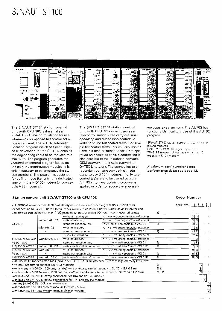
The S1NAUT ST100 station controlunít with CPU 102 is ihe smallestSINAUT ST1 telecontrol staíion for usewherever a low-priced íelecontrol solu-tion is required. The AU102 automaticupdsting program which has been espe-cially developed for the CPU102 enablesíhe engineering costs to be reduced ío amínimum. The program generales therequired telecontrol program based onthe mserted input/output modules, it ison!y necessao/ to parametenze the sta-tion numbers. The program is designedfor polling mode (i.e. only for a dedicatedIme) with the MD100 modem (or compa-tible V.23 modems).
The SINAUT ST100 station controlunit with CPU103 - when used as atelecontrol station - can carry out smallopen-loop and closed-loop controls ¡naddition to the telecontrol tasks. For sim-ple telecontrol tasks, this unit can also beused m a master station. Apan from ope-ration on dedicated Imes, a connection isalso possible to the telephone network,GSM network. trunk radio network orDATEX L network. The connection to aredundant transmission oath is madeusing two MD 124 modems. If only tele-control íasks are to be carned out/theAU103 automatic updanng program isapplied in order to 'educe the engineer-
ing costs to a mínimum. The AU103 hasfunctions identical to those of the AU102program.
SINAUT ST1Q2 stsi.cr ccrfo j« : .-. -. --e ••:•>•towing modü'BSCPUlu2;or2d VDC. a-gi:ai -p- j - - .;.TltVlOf IB telecontrol internes r»v;j , o O
, MD124 Tooem
Máximum configurations andperformance data: see page 12.
Station controí unít SINAUT STTOO wfth CPU 102
reí. EPROM memory module 375-Al [8 kByte). with standard moüntirg -3 's MS 710 (530 mm),for connection to 24 V DC or to 115/230 VAC, 50/60 Hz vía PS 931 pcwer s^coiy orvta PE buffer unit.Use only as outstaíion with max. 7 I/O modules [thereof 3 analog 70 T»OC¡ "-áx 4 counted valúes
Order Numb«r
6NH1021- !
24 VDC
11 5/230 VACwithPS 931 (2A)11 5/230 VAC/PE11 5/230 VAC withPS 931 (2A)115/230 VAC/PE
without AU102
with AU 1024)
without AU102
withoutAU102with AU 102
4)with AU102 i)
without installaíionwnh insiailation/standard function testwuh installation/Standard function testwiihout installationwuh installation/standard function testwuh mstallacon/síana. fn tes'v/ith installation/standard function testwuh instailation/stand. fn tes:
•j- .va'1 n-g^nt^g enclosure/cabmet'.r .-. ; —ourting encfosure/cabinet- ,• í -:o r wali enclosure WG 01 2)'.< .-.a "iojn:,ng enclosure/cabinet-•• . i "<j r .vail enclosure WG 01 2)
• ' .-. j -"c^nt.ng enclosure/cabinet• .- ••- 1 1 -ncurimg enclosure/cabinec- - ; -j i .valí enclosure WG 01 2)• •- -; - jva-.\e WG01P 2)
• ' .-. )•' —o^nt^g enclosure/cabmet• •. ••'. - .va'' endosure WG 01 2)
-.' i .-ii »- '.van enciosure WG 01 P 2)
3M33J.a.77
77
3
H3
E«3c
'~j
8¡B33
cG
wtth TIM 01 IB for dedicaied lines (prívate or PTT). SIMAUT ST protocci .-. •- "-essage memory (52 kByte]• withoui Modem to connect ext. V.23 Modems 8)• with modem MDIOO 11200 bos. half dx/2-wire or 4-v/ire. can be taoqec ¡r». SL 7Ql-¿BJ (0.8 m) 5) oí• with modem MD12¿ Irnax. 1200 bos, *alf dx/2-wire or d-wre, car ce "rc-íO i» 5L 70'-4BJ (08 m| 6) 12)
i
3 ' 'E"Di ' :
.vi tn bus uní BM 700 C icnmp connect-on) for ÍIM ana any I/O mod.iie '•,v th bus Lmt 3M 700 S (screw conrectian) 'or TIM and anv I/O moauíe 5 •wirnout SiMAflC S5-100U system manualwth S.MATIC S5-100U svstem manual, Germán versiónwitn SIMATIC S5-100U system manual. £rglisn versión 2

Station control unit SINAUT ST100 wíth CPU 103 Order Number
ircl EPROM memory module 375-A2 II6 kByte), mounting rail NS 710 (530 mm),for connection lo 2¿ V DC or ;o 115/230 V AC. 50/60 Hz vía PS 931 power supply
or va PE buffer unit.
6NH100&-
I i
24VDC
11 5/230 VAC withPS 931 (2A)
11 5/230 VAC withbuffer unit115/230 VAC withPS 931 (2A)
11 5/230 VACwitnbuffer unit
withoutAUlOS
with AU 10311)
without AU103
without AU103
without AU103
11)
with AU 10311)
withou installationwuh :nstallation/standard function test
with installation/standara function test
without installationwuh installation/standard function test
with instalfaiion/standard function testwith installation/standard function test
with mstallation/standard function test
for wail mounting enclosure/cabmetfor v/all mounting enclosure/cabmetmstalled m wall enclosure WG 01 2)insteiled in v/all enclosure WG 02 2) 3)for wall mounting enclosure/cabmetmstalled in wall enclosure WG 01 2)insialied m wall enclosure WG 02 2) 3)for v/all mounting enclosure/cabmetfor wall mounting enclosure/cabmetinstalled m wall enclosure WG 01 2)mstalled in wall enclosure WG 02 2) 3)mstalled m wall enclosure WG 01P 2)mstalled in wall enclosure WG 02P 2) 3)for wall mounting enclosure/cabinetinstalled m wall enclosure WG 01 2)installed in v/all enclosure WG 02 2) 3)instailed m wall enclosure WG 01P 2)mstalled m wall enclosure WG 02P 2) 3)
with TÍM 0 1 1 B for dedícated unes (prívate or P ¡ i ). biNAU 1 S 1 protocol, witn message memory (t¡'¿ :<byte)• wnhout modem to connect ext. V.23 Modems [e.g. for data network DIR) 8)• with modem MD100 (1200 bps, half dx/2-wire or dx/4-wire, can be lapped in). SL701-4BJ (0.8 m) 5) 6)• with modem MD124 (max. 9600 bps. half dx/2-wire or dx/4-wire, can be tapped in), SL 701-4BJ (0.8 m) 5) 6) 121
3333
4
d
•*
7
7
A
BEF
BE
PAB
7 |E
7 FMG7
tí
S
H
BE
B | F
3 , J
wuh TIM 01 1 8 for Telepnone and GSM Networxs, SINAUT ST protocol, wuh message/call number memory (52 kByte)• without modem or GSM-KIT• with MD125dialling modem incl. cable connector for TAE6N, with SL70MBJ (0.8 m) 6) 9)• with GSM-KIT MI, with SL 701-5BN (2.5 m) 13)wun TiM 011C for trun* radío SINAUT ST/MAP 27 protocol. wiih message/call number memory (52 kByte)xv.tn ;nterrupt bus una ABM 700 C (crimp connection) for any module (TIM. I/O)with bus unit BM 700 C (crimp connectíon) for any module (TIM, 1/OJwith mterrupt bus unit ABM 700 S (screw connection) for any module {TIM. I/O)with bus unit BM 700 S (screw connection) for any module (TIM, 1/0)
10)
10) Mwithout S1MATIC S5-100U system manualwith SIMATIC 55-1OOU system manual, Germán versiónwuh SIMATIC S5-100U system manual, English versión
Options for Waíl mounted Enclosures WG 01, WG 01 P, WG 02 and WG 02P
LAMP Installaíion oí cabinet IÜ--Q incl. fault signalling (In ¡he piannmg stage. a digital outputmusí be reserved to £• ate the cabmet lamo; noc for 5T1QQ-Q21)
6NH1740-OAA01
ST-DOSE Installaíion of a socket incl. circuit breaker 6NH1740-OAA1Q
PUFF.BAT. Bufíer Battery for CPU 102/103. Absolutely required when usmg ths CPU withoutEPROM 375-A2 memorv module, ootional fof use wuh rremory module.
6ES5980-OMA11
Key:
1} ST100-Q2 can onh/ opérate wuh the selí-aflaming pro-grarn AU102. which 'S mcluded m the TD1 software-pacfcage edílion A07.
2) ¡nsia.laiion in wall mounied enclosures me!. CE cenifi-cation (fequtred for iimit class 3. degree of proiectionIP55V The wail-mounted enclosures are deliveteo witnhuillín STIOO station control units ana can be equip-oed optionally wiin a cabmet lamo and a mains socketA¿l caoies are snietded ana grounded at one comí.Grcunding acccrcng to VOS regs. (nec. 'or 24 V d cneg grounaeo reiwor<. pos. grouraed network•eauíres a c convenen Caoies a.e feo ¡n trnrn nelowThe wall-endosures WG 0)P/Q2P a*e connected axter-naüy to 115/230 V AC- ^or tectimcal cata of Ihe Dulferunit ar.3 dir-engiors oí cas.ng see page 11
3) Incl. 2noNS 710stancara 5ec:<onal rail and IM315interface.
•l) ñequired delanes Sta:ion no ar.ü baud ratel AU1D2 isoníysuiEable for a SF:00-02 station with CPU 102 on adedicatea Nne and wm co'iing mode The program rsdesignad for max 7 -O modules itfereof max. 3 ana-log l/O modules! The aigitai i/O moaule DEDA 482-Acan not be used
51 PTT apofovaí For PTT eased linas of tne DBP Telekom.6) Peírnissible i 1
amoieni temoerati,res ¡VD100 I.MDI2J ÍWD125for wall mounnng !0 55'C O SO'CtQ 50°C
Q -*0°C .0 -15'C ¡O 4QBC7| Use as master or outsration >noc as node stauon).
max. 1 TIM Ot IB. eQu'pmtínt sea page 12. lechndata/max. amount of orccess «alues see pages 12. 13
8) DIR = Dala network 1300 or 1200 bes as.rxirrc'-oosiV24/V.2e/X.2rjbis«.21b.s mterfactí-
9) PTT approvals for Telephone netwof< a' O^'-T-JOVAustria and Swiizerland exrst.
10) For courtied pulse acquisition aDsoiutety regLiíed jsIst bus module!
1II Reouired detalles' Station no. ana oaud rate1 AU'03 -sonry suiíable for a ST1CO station nviin CPU 103 on adea/caled line and wuh polling mooe The p'ogfam >soesigr.ed for max. 17 l/O moduies iirereol "-3x ' ana-cq f/0 modules! The digital l/O moawe DE2A ití2 Acan not De usad.
12) VID 124 up 10 19 200 bps oulside cf SlNAU r •; n '131 Tecnmcal data oí GSM-XlT MI see cage uI-) TrunV radio components see oage '-i

SINAUTST115
modj'es.wm'/O r
lí very highdemands should beplaced on the avail-ability and faulí tole-rance, the redundantstation controlsystem SINAUTSTl15/RXcanbeused.
Au" 3Ti '5 s:at.cr coercífcrcwipg r-cdi. esPower SuCOiy *er 2d V DC. C 5 /O
' ' ÍEL :e eccr-
The SINAUT ST115 síation control unithas been developed for medium-sizedprocess station. Additionally the SINAUTSTl 15 station control unu can be used asa :e¡econtrol master or as a node station.Cornprehensive input/output peripheralsare available for data acouismon, open-loop control tasks and operation andmonitoring íunctions vía monitor/key-board, desk and panel. 1024 digitalirpuís/outputs and 64 analog inputs/out-puts can be connected.
In addition to connection to prívate linesor to the telephone network, the unit canalso be connected to the EURO-ISDNand to GSM or the trunk radio. Thecorresponding moderns can either bemtegraíed direcíly in ihe unit usingmodem adapters or connecíed externally.Daca transfer <s vía the intelligent TIM 11transmission processor with matchedinterface.
It canonlybeused as an outsíation and consists of oneCPU and two TIMs íor data transmissionon an redundant link.
The station control sysíem SINAUTSTl 15 can be used data point onented orfor object onented data exchange.
Further features of the SINAUT ST115staíion control unit:
All components - power SLopiies,central processing unas, transmis-sion and communication processors.modem adapters/modems. signa!conveaers and penpheral modules -are accommodated in plástic safetyhousings and are particularly rugged.
One of four central processors withdifieren! performances can beselected dependmg on the require-ments.
O The mecnanical modulecoding means :hat >t -simpossible to ccnfusemodules.
O Modules and signal- cables can be assem-
bled and screwedtogether rapidty.
O Simple reolacesbilitywith snap-on block-type moauíes
O Adapiabiíity throughthe use of difieren!input and ouiput volt-ages as weil as ihefineley graduatedmodular expansióncapabilityof the mputs.outputs and -nemory
O Standby and maintenance personnelcan be called using C1TYRUF and tr>eMessage Service.
Máximum configuratíons andperformance data: see page 12.

Station control unit SINAUT ST115 Order Number
for transmssion on dedicated tines (prívate or PTT),on aiallirg networxs or direct tmks. with mountir.g rack CR 700-2, mcl. assembly/installationana standard function test
6NH11S2- [_ ! I
Power sjpp'V modulePS 3 with bufferbatte'v íor RAM(not fcr TIM)
withoutexpansión unit
witn expansiónunitER 701-1
24VDC 1-20. . t-30 V). OUEDUE5V/7 A. witnout fan24VDCI+20.. .+30 V).outpui5V/l5 A. wuhían115 V/230 V AC, ouTput 5 V/7 A. v/nhoui fan1 1 5 V/230 V AC. output 5 V/l 5 A, with faníor wall mounred encíosure or caoinetinstalletí in wall encíosure WG 1 1 ÍHxWxD - 760x600x350 mm)mstalled m wail encíosure WG 12 IHxWxO = 1200x600x400 mm)with mterface module IM 305, lor wall/cabmet ínstallationwith mterface module IM 305. irs:ailed -n wall encíosure WG 12with 2 IM 306, SL 705-0, for wac/cabmet installaiionwnh 2 IM 306, SL 705-0. mstallea m wail encíosure WG 12
2)
2)
3M)4)5)
6)4)6)
7)4)7)
wnh casing and teiecontrol nterface module 8)• TIM 11 SL V.24 (ST protocoi) without modem to connect ext. V.2^ modems (e.g. for data network DIR) 9)• TIM 11 SLV24 (ST protocoi) with modem MDlOOand SL701-4AL (1.5 m) 10) 11)• TIM 11 SLV 24 (ST protocoi) with modem MD124 and SL701-4ALÍ1.5 m) 10) 11) 19)• TIM 11 SL V.24 (STpfotocol) with modem MD125 and SL701-4AL U 5 m) 10)• TIM 11 SLV 24 1ST protocoi) with modem adapter MOA-F2 mcl. modem KS 2000, SL 701-4AL(1.5 m) 10) 11)• TIM 11 SL TTY (ST orotocol) for direct link vía TTY interface 12)• TIM 11 SL RS422-A iST protocoi) for direct 'mk vía RS 422-A/485 interface 13)• TIM ]4 (4-FW oroiocoi)• T M 15 ¡FW 535 orotocol)
14)14)
• TIM 11 C (ST-/MAP 27-protocol) for uunk radio• TIM 11 C (ST-/MAP 27-protocol) forirunk radio, with C-KIT, wiih SL 701-5AM (2.5 m)• with CPU 941 mcl. EPROM memory module 375-A2• with CPU 942 incl. EPROM memory module 375-A4• wuh CPU 943/1 incl. EPROM m • -.ry module 375-A6• with CPU 943/2 mcl. EPROM r- •• v module 375-A6• with CPU 944/1 mcl. EPROM rr . .^/module 375-A6• with CPU 944/1 inc!. EPROM mernory module 375-A7• w¡th CPU 94d/2 mcl. EPROM memory module 375-A6• with CPU 944/2 incl. EPROM memory module 375-A7
21)21)
(16 Kbytes). witn mternal RAM (2 Kbytes)(32 Kbyies), w.th .nternai RAM (10 Kbytes)(64 Kbytes), wiih tn:ernal RAM (48 Kbytes)(64 Kbytes}. wi:h miernal RAM (¿8 Kbytes)
17)17)17) 18)17) 13)
(64 Kbytes), w:in mternal RAM (96 Kbytes) 17)18)1128 Kbytesl. w tn mternal RAM (96 Kbytes) 17)18)!64 Kbytes), wr.~ .r:emal RAM (96 Kbytes) 17) 18)[128 Kbytest. .vin n-ernal RAM (96 Kbytes) 17) 18)
• TIM ' 1 TEL (ST protocoi) for teiephone and GSM networks, without modem or GSiM-KIT• TIM 11 TEL (STprotocol) for telephone network, with dialling modern MD125 incl. cable connector (6 m) to 10) 15)
TAE6N, with SL 701-4AL (1.5 m)• TIM 11 TEL (ST protocoi) for GSM network, v/ith GSM-KIT Mi, wnh SL 701-5AN (2.5 m) 20)• TIM 11 TEUST protocoi) for EURO-ISDN, with MOA-MDM, with LGM 64K, with SL701-4ALI1 5 m) 16)
v/ithout SIMATIC S5-115U system manualwith SIMATIC S5-115U system manual, Germán versiónwnn SIMATIC S5-115U system manual, English versión
Options for Wall mounted Enclosures WG 11 and WG 12
LAMP Installation of cabinet lamp incl. fault signalling |m iré _ ¿r-»v«g stage.a digital oulput should be reserved to actívate ihecac r#\i
6NH1740-OAA01
SIFl B Installation of a radio-mterference suooression futer 'or iimit class B) 6NH1740-OABOOST-OOSE tnstallai=on of a socket mcl. circuit breaker 6NH1740-OAA10
Key:
II Eouipment: see page 122) VVhen retrofining wilh a fan. load up !o 15 A. A ían is
recessary when using a CP (see SIMAT1C 551 or wnen¡nstalling in a wall-mounied enclosure cr cacinet.
3) Instaiiauon o( exoansion umi noi oossible latend) .nstaila*.on in wa¡]-moun;ea e^tíosufe ir.cl CE certifi-
cation Idegree of pfoíection .P55) The wall-mountederclosures a(e suopued v/iín 5T' 15 jnits mstaltea andcan oe eauopea ootianally w«n cacmet lamp ana wnna socxet A.l iré canles are sr¡eideo and gíounoed alOne pOini GrounCing acc '.O VDE 'egüations,for 2A v d c "egative grouraed retwonc a oosiiiveg'OundeC neiv/ofk recuifes a d c convenen. Carnesare 'ed >n fíom beicw
51 Expansión unt i" -.••> .--Jeo aief1
6] r-xed adress^ng - . t . ' j¿ í ;s rra* -l) onty m CR7CO-27) Fres adress<ng. ¡ '. ••'•:t,.es ;an ce pluged ;n any slot31 For 'urttier TiMs <>*# L.i^e 9} Dlfl = Daranetwc-V JGC/1200/2dCOMaOO/9600 bpsl
Interface V2-A/23A :OE s/X 21ois10)Perrr.issinie MD'OO/ ¡ |
arrpient lemperai^es <S2000 ¡MD12A 'wD12555'C .0 60°C 10 50°C
O -IQ'C :0 ¿5 ;0lor /jal* mooni fsm sasmgAvaii e^c '.sThe modems MD'OO* VCi;4 índ MD125are m- 'stailea exiernaily en a staiüa'a .-nounting rail (snao-anl 'n siandaroueo waii-"-oi.nied enc¡osures orcandéis 't is msia.lea on r"e PS rail For versions with115/230 V AC supoiy ^citage a sepárate 2¿ V pcwerSupply oni[ m^st oe planned íof :re MDIOO.ard M0125. a g PS 930
Longer cacle connector SL 701 -lAN 12 5 mj s paga u11} PTT approval for PTT circuns exists121 Paml-topoini Imk. max. distance '000 m 3600 nos131 Poini-to-ooini lirVs and multi-po-nt imKs lean be lapcea
ni. max aisiance 1200 m. 5500 bos• -i Use only aíter consuiíatian witn ANL A72X15i PTT approval for Telephone netwoik of Germany.
Aus;na and SwuieMand16) Tecnmcaí data ISDN components see qage 20171 Techmcal soeCíficanrans oí CPU see sage '21SI The EPROM reo'aces pan af the mternai ^AM 71-a
seciion of me RAM wnicíi :s 10 lorger a-.a >ac e s tresame lengtn as the arogram presen! an t"e íP^CM
191 MD124 can. oe jsed up to 5600 Sos nnax20) Técnica! dala GSM-KIT .MI seesagel- i21) Tr^fk faaio compcnenls' see cage M

SINAUTST135andST155
The SIMAUT STl 35 and STl 55 stationcontrol units are sukable for processstations wilh extensive open-loop andclosed-loop control tasks, up to centralcontrol stations with color monitor/key-board, primer, desk or panel. Branchednetworks with high-performance nodesiations with a high data íhroughpuí canbe constructed if required. 1024 digitaltnputs/outputs and 192 analog ¡nputs/out-puts can be connected.
The units nave the same transmissionand communication propemes asSINAUT ST115. Multi-processor mode ispossible ¡n addition, ¡.e. up to four centralprocessors with th^r own programmemories and mam memories handledifferent functions in parallel in one unit.Data transfer via the interna! bus systemis optimized vía a coordinator.
The SINAUT ST155 exceptional featuresmclude comprehensive memon/ configu-ranons, very high processing speed andvery short cycle times.
The redundant. fault-tolerant versionscan be used if ven/ high demands are plac-ed on the availability and fault tolerance:
O The redundant SINAUT STl 35/RXand ST155/RX uniís can be used as atelecontrol síation or master síation.The telecontrol station contains aCPU and two TIMs for data íransmís-sion on a redundant link. The rnasterstation always contains two CPUs aswell as two TIMs per transmissionlink (single or redundant)
O The fault-tolerant SINAUT ST155/HXcan be used as a telecontrol station,master station or submaster station.A single or redundant transmissionlink can be used. The H versión isprimanly used if open-loop andclosed-loop control tasks are to beprocessed redundantly by two CPUs
StNAUT ST135 siai'on con'roi ur t wtth thefcüowirg rrotJules:Ccordirator module. 3 CPUs. cor^-n^r canoprocessor. 2 TlMl 1SL V24 teiecortroi '^:<jrfmodules, 2 MOA-F2 rnodefn anao'ers forXS2QQO r^oae-rs. 7 '/O -retímos, "•taracemoduie io extensión 'acs
Both versions are available for simple aswe!l as for object orieníed dataexchange. In the master síation is singleor redundant Industrial Ethernet buscommunication possible to theLSX SCADA system.
Funher features of íhe SINAUT ST135and ST155 station control uniís:
O The compact 19-inch subrack of thestation control unit provides 21 slotsfor central processors. transmissionand communication processors.,modem adapters/modems. s.qralconveners and penpherai modules
O Signal converters are addres:>ea v.aswitches and can be msened r-*oother slots without changiry 'hesoftware
O The power supply with 2 nre^meafan subassemblies and a hdc'"- ,obatíery is of space-savir.g -'¡es jnunderneath the subrack
O The coordinator enables Trocí nro-gramming (on-line and o': -rw ¿f .3!!central and communicancf cf<es-sors
O Standby and mamtenance Cfr'-.-nnelcan be called using CiTYP^- i- i theiVlessage Service
Máximum confígurations andperformance data: see page 12.
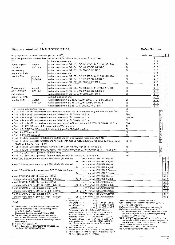
Station control unit SINAUT ST135/ST155 Orde/ Nümber
for trarsmission on dedicated unes [prívate or PTT),on dalling network_5 or direct :inks, mcl. asserrbly/installation and standardjunciion r
61MH1352- I
Power supplyDC 24 V.mci. bac'<-upbattery 'or RAMírot for TIM)
Power supplyAC 11 5/230 V.mcl. oack-uDbattery for RAM(not for TIM)
output5 V/1 8 A
output5 V/40 A
output5 V/1 8 A
output5 V/40 A
without expansión unitwith expansión unit EG 183U DC, IM 300-3. IM 312-31. STL 760 2)with expansión unit EG 184U DC. IM 300-5C, IM 312-51 2)with expansión unit EG 1S7U. !M 300-5C. !M 312-51 2)without expansión unitwith expansión unit EG 183U DC. (M 300-3, IM 312-31. STL 760 2)with expansión unit EG 184(J DC. IM 300-5C. IM 312-51 2)with expansión unit EG 187U. IM 300-5C. IM 312-51 2)without expansión unitwith expansión unit EG 183U AC. IM 300-3. IM 312-31. STL 760 2)with expansión unit EG 184U AC. IM 300-5C, IM 312-51 2)w.th expansión unit EG 187U. IM 300-5C. IM 312-51 2)without expansión unitwith expansión uní EG 183U AC, IM 300-3, IM 312-31, STL 760 2)with expansión uní EG 184U AC. 'M 300-5C, IM 312-51 2)with expansión uní EG 187U, IM 300-5C. IM 312-51 2)
3333
A
cDF
LfJA
4
4
CD
4 | F
7 | A
7
7
7
8
88
8
CDF
A
CD
F
with relecontrol mterface module 3)• TIM 11 SL V.24 (ST proiocol) wuhout modem to connect ext. V.24 modems (e g. for data network OÍR) 4)• TlM 11 SL V24IST protocol) with modem MD100 and SL 701-4ALH 5 m) 5)6)• TlM 11 SL V.24 (STproíocol) with modem MD124 and SL701-¿ALM 5 m| 5)6) 14)• TlM 11 SL V.24 iSTproiocon with modem MD125and SL 70MAL (1.5 mi 5]• TÍM 11 SLV.24 (STprotocol) with modem adapter MOA-F2 mcl. modem KS 2000. SL 701-4AL (1.5 m) 5) 6)• Tlívl 11 SL TTY (ST protocol) for tíireci Imk vía TTY interface 7)• TlM 11 SL RS422-A (ST protocol) for direct link vía RS422-A/485 inierface 8)
TlM 14 14-FW protocol)TlM 15 (FW 535 protocol)
9)9)
• TlM 11 TEL (ST protocol) for telephone and GSM networks, wuhout modem or GSM-KIT• TlM 11 TEL (STprotocol) for telephone network, with dialling modem MD125 ¡ncl. cable connector 16 m) 5) 10)TAE6N, with SL 701-4AL 11.5 m!
• TlM 11 TEL (ST protocol) for GSM network, wiíh GSM-KITM1. with SL 701-AN (2.5 m) 15)• TlM 11 TEL (ST protocol) for EURO-ISDN. with MOA-MDM. with LGM 64K. with SL 701-4AL (1 5 m) 11)• TlM 1 1 C (ST-/MAP 27-protocol) for trunk radio 16)• TlM 11 C(ST-/MAP27-proíocol) for trunk radio, wiíh C-KIT. with SL 70 ! -SAN (2.5 m) 16)• with CPU 922. with memory card EPR 376-64 (64 Kbytes)
12)• with CPU 928, with memory card EPR 376-64 164 Kbytes)
12)• wiíh CPU 9288, with mernorv card EPR 375-64 [64 Kbytes)
12)• with CPU 948-1 1640 Kbytes intern. RAM)
and memory card FL-EPR 374-512 (512 Kbyies) 12) 13)• w-th CPU 948-1 1640 Kbytes intern. RAM)
and memorY card FL-EPR 374-1 024 (1 Mbyteí 12) 13¡• with CPU 948-2 Í1664 Kbytes mtern. RAM)
and memory card FL-EPR 374-512 1512 Kbytes) 12) 13'• with CPU 948-2 11664 Kbytes mtern. RAM)
and memory card FL-EPR 37d-1024[l Mbyte) 12) i?.
ruX
y-.viin manual 135U/922 Germánw:h manual 135U/922 Englishv, th rr anual 135U/928 Germán•,vn TiaiLal I35U/928 English,v- -ar-jai 135U/928B Germán.-, -n T-anual 135U/928B English,-, — "•j'n.al 155U/948 Germán,.,,-r. f^a^uai 155U/948 Englishí. •*• ~ 4r -jai 155U/948 Germán.-, - - ínual 1 55U/948 English.-. -n -j-xal 155U/948 Germán,., .* — jrjai 155U/948 English.-. - "-jnuai 155U/948 Germán.... a-xai 155U/948 English
i
i ;
ohQ
1
1
224.
¿1
5
21
2121
21
5|2/7
12
3 18¡ 2
Key:
t) Technical scec . quanlity f'amewori;. equipment: seepage 12 Remeiroef radio suopression regulanons-.vren limn c'ass B -s reauredOn reauesi Standard cabirets STS-l and STS3
2i =cr Tech soecs *or expansión umis ana 'fiierface•T-cau es see S"50 catalog The basic unit intsrfaceTiodbie 3'2 3/-5 contams a O 5 m ccnnecfcng caole fofstac-:ed •ac-.s
3) f .i'her "IM? see page '-&\l = Cara ¡-ev/or* ¡300/1200/2^00/^600^600 bpsl
•nrerface V 2¿N 2S/X 2üEis/X 21 nis
51 Pefinissible
fof wall mom' -.¿ _ ; a C ;0_ SO'C 10. 50"Cm capmet ,• JQ'C JOT ¿5'C |0 4Q'C
The rnodems MD' •'.<) *.'C ; i- aro WD125 are in-stalted exiema:iy :n 3 ifa^uara n*ounting ^ail Isnap-on| In wdll-moij'"rO •>"• '', iw"is Qf caomets i! ismsiaHed on'-e PS , - • .*-s 0^5'.v'h 115/230 VAC suoply voi'agtt i •*•!. j' •:« U -' oower supply unnmust De plannes '.-? '.!2'"0 MD124and MD125.eg PS 930 Largar :.ic rí ..-nec'Of St. 701— AN(2 5 mi see page u
61 PTTapoiovaí'T 3r~ ; f-v e-.s*s71 Poinfto-pomt n^s - J- -''í'ance 'OCC r^. 3600 EOS31 Poini-ro-pomt l.r-r s ^ —^.-i pcirt -ir-<s (can De tacped
m). mat distance iZCOm íc>~"} Ccs
9) Use only afier consullation ^/ith AiSL ¿?2101 PTTapprovaí fof 'elepnor.e neiv/crfc of G^'^an
Austria and Sv^itzerlana11) Techmcal cata iSDM coniDonents see cags 2012) Tecfimcal soeoficaiions ot CPU ses oage '2
All CPUs except CPU922 feoi^ire 2 s^ois Tre -^includes the svstem manual and megi^ide oí me CPU specrf-ea
'31 The EPPOM replacespan of *ne ".ef^sectiQn of ine RAM wmch. is no onge' 3same lergtn as ine pr-gram aíesdnt y
1-i) MD12¿ can ce -sed up ro 3600 ops151 recnmcal data GSM-iClT MI see naqe '!6) rfunt raaio comoonenis see page '-i

S NAUTTelecontrol
Neíwork confíguraEions and operating modes
SINAUT 3T1 síaíton control and protection systemTIM 011 and T1M 11 íransmission processors
CfíyrufSINAUTSTUtesíunit
DCF 77 reaJ-time clock moduleWa!l enclosures and battery backup units
Modems MO100, MD124, MQ125Connection ío EURO-ISDN
Connection to fiber-optjc cabteswith RS 435 transmissíon nxxíulesLTOP Une transformar with overvoltage protectionFour-way transíormer
SINAUT TD1 standard software
1 2M
15
151 6i "
18
10

lelecontrol Componenís SINAUTNetvvork Configuration and Operating Modes
Network conf iguratiom'arKf óperating modea^dedicaterfUnes:."••'• " • •: '• :,V;*:*í;!-"S^Us-:. ::Hr-íá'^^-^-""-^vrV ¿?: 5
o -o Poiní-to-poiní Polling modeCycüc mode
999o Y Y Y o
o-o
Star
Multipoint Lina
Combination ofpoint-topoint. starand Multipoint Une
Combination ofpoint-to-poínt,node, star andMuliípoint Une
Polling mode
Generat radio netwbrfcs::rJ::í;í:::*HÍÍ:r.UVíuS'.^irliííS
Radial field:star configuratíorv
Polling ands pon t aneóosmode
Radio relay:Line (wiíh/without frameregeneration)
PolÜng mode
r
Redundan
Swítched networks- Telephone- EURO-ISDN
Mobile radío networks- GSM (D network}- Trunk radio
Radío cali services- Cityruí (telephone or
GSM network}- Message service
(trunk Unes)
Dedicated line wiíh redun-dant íransmission line viadedicated line
Spontaneousmode
Polling mode
Fiber-optic cable/copper cable comblned network.
FO
FO
Dedicaíed line with redur>dant íransmission íine viaswitched network
Various Combinationnet\vorks:for example, fiber-opticcable and copper cable
Polling andSpontaneousmode
Polling mode

lelecontrol CornponentsSINAUT
SINAUT 'STTsUrBoft control and proteetion system
Application SINAUT ST1 is a station con-trol and protecíion system de-signed formonitoring andcontrolling process plañís indistributed configuralions.SINAUTST1 is basedonSIMATIC S5 programmablecontrollers and additionallyfeatures specific hardwareand software components.Telecontrol and auíomaiioníasks can therefore be pro-cessed by a single system.SINAUT ST1 is used with theSIMATIC S5-100U/115U/135U/155UPICS.SINAUT ST1 also permits the
implementation of compre-hensive hierarchically struc-tured control networks con-sisting of outstations. nodesand telecontrol centers linkedvía VVANs.Prívate lines. radio links. GSMand trunk radio networks,post office and public chan-nels such as telephone lines,EURO-ISDN or direct dataconnections (DDC), can all beused for data Communicationsbeíween the individual sys-tems of the network. In addi-tion, a radio-paging service(Ciíyruf) can be used for call-
ing standby personnel. Withdedicated lines, communica-iion can be vía copper cableor fiber-optic cable.Links in the local range canbe established using theSIMATIC NET (Profíbus, In-dustrial Ethernet) LANs.COROS MMI systems enablecentralized and distnbutedoperator-process cornmu-nication. Standard interíacesto the SINAUT LSX andSAMSY X higher-level net-work control systems areavailable.
Deslgn A TIM transmission processorand a modem are required aieach poiní where S5 PLCs areconnecíed. At least two TIMsand two modems are neededat each node station. Redun-dant or fault-tolerant trans-mission paths, síations andcontrol centers can also beimplernented.Examples of WAN topologies:• Point-to-point• Star• multípoint line• Combination of point-to-point, node, star and multi-point line
• Switched network• Radio network• Mobile radio network
Localprocess
Higher-level
"Í ""
Conlral cenler
"I"
V/AN
Loca! iprocess Í
Node stalion
T "
í"" J~^ „ ~~*- Slation ;— — Stalion ! - Slalion '—
"rrr1 ~"rrr "irrPrccass/pccduciicn pfant
Fíg. 8/1 Síructure oí a WAN control networK
— Slalion t — -iMu.il dis-S'ay .
1 Máximum complements and perform
1i1 Digital mputsi used for counting pulse acquisition9). Digital ouiputs, Analog mputsi Analog outputs, Numberof TIMs/CPs that can be plugged inj Applicaíion as substatíon:i - Dedicated line/telephone/mobííe radio link5'i Application as ncde siation:, - Deaicated line/'telephone/mobíle1 radio iink3'i Application as control cenier:i - Dedicatetííine/íelephone/mobile1 radio Jink5'1 Use for telecontrol: Use for open and closed-loop control, Program memory ¡n KB1 Data memory in KB! Memory requirements (or Program memory¡ standard staíion tele- _ .1 . . ,,, Data memory( conirol programé
anee íeatu
S5-100UW
CPU102')56
4
56
12
6
1
res of SINAUT ST1
Ith I ss-nsuwCPU ; CPU 941
136 1288 . 8
136 12828 3214 32
;J1 ,31
i• / - / -
- / - / -
./ . . . ' . / .
-/ - ' •/ -
IthCPU 942
256
8
256
48
48
6
CPU CPU
943 944
512 1024
16 128
512 1024
64 64
64 64
6 9
S5-13SUwlth | S5-1S5Uwftfi
CPU CPU928BJ CPU 948
922 ;
1024 1024 ! 1024
32 128 , 128
1024 1024 i 1024
192 | 192 - 192
192 | 192 192
8 1 1 5 . 1 5
• / • / •
. / .6J/ .6)
. / - / . ./. . -/. ; ./.?>/ .n
.-Total:4
Total:
•
•
Total 1620 2
•
.
32 Total [ Total: ¡64 ' 6 4 ! Total.10 «18 96
117 !1
4 i : 25
22 ¡ ¿6 ,' 640/1664
12.1
I 3
!) Up to 7 slots for I/O modules; no addilionaluser program
21 Up to 17 slots for I/O modules.-' A primer can also be connecied vía a
communication processor
51 Mobile radio O networK and irunk radio6í Only !o substations. not to control center7' Only to substations. not lo node station
9' Transmií; 32 messages. 4 analog var!Sbles.1 counter; Receive' 8 commands. i setpoini.1 TIM transmission processor
9) Max. IQHz
12

Telecontrol ComponentsSINAUT
TIM
Application One TIM 011 transmissionprocessor can be installedper síation and control ceníer.It can be used in the SIMATICS5-100U and is available inthree versions for data trans-mission:
on dedicated lines (prívateor post-office)over the public telephonenetwork, the ISDN netv/orkor GSM mobile radio neí-vvorkover trunk radio netv/orks
Design The TIM 011 processor
• plugs into slot O, 1 or 2 of abusunitof theS5~100UPLC;
• has a RAM/EPROM memorysubmodule with EPROM forTIM íirmware and RAM forstoring message frames andnumbers;
has a V.24 (RS 232 C) mo-dem interíace (25-pin sub-miniature D connector)
has 4 LEDs:TxD = send dataRxD = receive data,RTS = request to send,BATT = backup batterymonitoring.
Functions TIM 011 can send and receivedata simultaneously in the fol-lowing modes: POLLING,SPONTANEOUS WITH/WITH-OUT DIAL-UP PROCEDURE,CYCLIC WITH/WITHOUT AC-KNOWLEDGMENT. The POL-LING and CYCLIC modes areused for data transmissionson prívate dedica^J lines
and post-office channels. Ondirect data communicationlines of the Post Office, datatransmission is cyclic. TheSPONTANEOUS WITHDIAL-UP PROCEDURE modeis used for all dial-up connec-tions over the public tele-phone network.
Technical specrflcations
Transmission protocol
Interíaces
Curren! consumption
Connector
SINAUT ST
V.24 (RS232C)
0.1 8 A
25-pin submíníature D
Heat losses
Space required
Weight
1.2W
1 slot on bus unit (¿5 mrr/ 1mountlng wkjth)
0.5kg/1.1 Ib
Ordering data
TIM 011 transmission proces-sors:• T1M 011 B SL
Dedicated linas (prívate or P.O.)
• T1M011BTEL
Public telephone ner.vork. ISDNnetwork or GSM mobile radio
• T1M011CTrunk radio network with BOSCHtrunk radio unit KF Chip TD
Order No.
6NH1 804-2BB01-3BB2
6NH1 804-2BB01-3CB2
6NH1 304-2BB01-3FB2
Connectíng cables:• SL701-4BJ (0.8 nV2.62 ft)
between TIM 011 and MD1007MD124/MD125
• SL701-5BN (2.5 m/3.2ft) betweenTIM 011 and GSM moa'em ortrunk radio unit
Order No.
6NH1 7Q1-4BJ
6NH1 7Q1-5BN
.J
13

leíeconirol ComponenísSINAUT
TIM
Application The TIM 11 transmission pro-cessor can be installed in sta-tions, nodes and control cen-ters The máximum TIM 11complement is listad on page12. U can be used in theSIMATICS5-115U/135U/155UPLCs and is available in fourversions for data transmis-sion:
on dedicated lines (prívateor Post Office)over direct link (without mo-dem)over the public telephonenetwork or GSM mobile ra-dio network as well as overthe pubhc EURO-ISDN net-work
• over the trunk radio neo-vork
Design and functions The TIM i 1 plugs into a CPslot. The four TIM 11 versionshaveaV,24(RS232C),RS422-A/485 interface cardand a RAM/EPROM memory
submodule with TIM firmwareand a RAM for storing mes-sage frames and numbers.There are 2 LEDs on the front-plate:
TxD = send data,RxD = receive data.The principie of operation ofthe TIM 11 is the same as forthe TIM 011.
Technical speciflcaíions
TIM 11 Transmission
proceasors
Transmission protocol
Interfaces
Currenl consumptionConnectorHeatlossesWeight (T!M 11)GSM network componenta• W1 module (contains ful!
S4-Handy functionality; can beattachea with terminal holder orVelero íastener)Dimensions (incl. termina!holder W x H x D)WeightOperatmg voltageTransmission powerSerial inlerface
• SAP connectorforconnectingthe Mi module to the antenna
• GSM network antenna (long)
SINAUT ST; for trunk radio wíthovsriayed MAP27
V.24 (RS232C) wiíh dedicatedline. telephone, EURO ISDN.GSM and trunk radío networkRS422-A/4S6 wrth LAN !¡nk
1.5 A25-pin subminiature D1.7W0.6hg/1,32tb
37xS5xl20mnV1.44 x 3.32 x 4.68 in
I50g/5.25oz3 - 32 V DC2W9-poJ. D SUB; V.24A/.28
3 dB anlenna gsln
Orderíng data OrderNo.
TIM 11 transmlsaíon proceasora;• TIM 11 SL 6NH1 802-5BA
Dedicated line (privaíe/Post Office)and for direct calling network (PostOffice provides modem)
• TIM 11 SL (K) 6NH1 802-OBANode TIM (dedicated line)
• TIM 11 SL RS422-A 6NH1 802-5BDDirect links wnhout modem
• TIM 11 TEL 6NH1 802-5EATelephone ret-//ork. SURO-ISDN orGSM mooile radio network
• TIM 11 C 6NH1 802-OFATr-jnk radio nehvor'< with BOSCH-trunk radio unit KF Chip TD
Trunk radio components• Trunk radio unit
H x W x D
MAP27 socketFrequency range
Power supplyWeight
• Optional hand unit
• Magnet-mounted antenna
• Hand radio unitH :< W x D
Frequency rangePower supply
Operating periodsWeight
• DC/DC converter
Bosch KF Chip TD29x150x 166 mnV1.13x5.85x6.47^1
RS232
Transmitter -110 to 430 MHzBecervef 420 to 430 MHz12VDC800g/28oz
Boscn HAS, fí speech ana datato be transmitted símultaneousiy
Besen
BOSCHHF12T172 x 66 x 33 mm/6.71 x2.57x 1.29in410 ío 430 MHzBaítery 7.5 V/700 mAhor 1000 mAhSor 8h530 g/18.55 oz wrthbanery 700 mAh
Inpuí voltage 24 VOutpuí «/ohage 12 VCurren consumption 2.1 A
Adapter casing(requirea íorS5-115Uonly)
Connectfng cablesbetweenTIM 11 andmodem/modem adapter• SL701-4AL
I 5 m/4 92 ft• SL701-4AN
2.5m/8.2ft
Connecting cable between TIM 11and JSM-M1 module or Irunk radiounit. 2 5 rr/8 2 tt
OrderNo.
6ES5491-OLB11
6NH1 701-4AL
6NH1 701-4AN
701-5AN
14

lelecontrol ComponenisSINAUT
GSM networR"^.rtftóÍ3fifl"ts*aficÍ'.fnjníc-ra^Ió-components (eoñífnüed) .-
Orden'ng data OrderNo.
GSM network componente andIrunk radio componenta')• GSM-K1TM1. 6NH9S40-3DB10
cc~SiStirg of Vi module v/ith termi-nal r-cicer/Velcro fasterer. SAP con-néctar GSM network anienna ílongj.
. C-Kit, 5NH9 S4O-3CAOOirslallalion kil ready mounted andwi*ec on a nounting panel for a con-trol center.'station for mstallation in áwa:l housing door or ?ree-stand¡ngcabmet. consisting of
; Other units and designs on fequest
Cityruf' " . _ ? ; " :-r
C 'riit (contrnued)8OSCH KF Chip TD Irunk radio unitwithouí HA3 tiand unit. <ncl fixing kiland holder BOSCH magnetic an-tenna /Mh stand and cable(5 m/16 4 ft). incl. antenna cable(4 m/13.12 rt). antenna with requiredconnectors. SVA 12 DC/DC con-verter SC 24
• C-Kit HASInstallation kit HAS as installation kitabove. bul incl. HAS hand unit
• PARA CParameíer assignment and stanupsupport
• HF 12TBOSCH handheld HF radio unit12T (or rressage sen/ice
Order No.
6NH984O-3CA01
on request
on request
Applica-tion andFunctíons
Remote monitoring of plañísautornaíed using S5-1151),-135U or-155U ¡s possibleusing the CITYRUF sen/iceprovided by the Germán PTT.
Requirements:
• Connecíion to the Germántelephone or GSM network
• Connection of MD 125 mo-dem (wlth telephone net-work)
• At least 16 Kbytes vacantuser memory in the SIMATÍCS5 device
TIM 11 TEL with reléase ver-sión 11 or later; reléase ver-sión 14 or later for GSM
The person carrying theCITYRUF receiver must bewithin the C1TYRUF callingzones.
Ordering data
CITYRUF software'or SIMATÍC S5, mcl. manual• On 3 V'2" and 5 '/a" diskettes• Manual for CITYRUF, in Germán
Order No.
6NH1 998-5AA186NH1 99&-5AA13
CITYRUF receiver AN6,with alphanumeric display. incl.cnarger unit and 2 NC batteries
The TIM 11 TEL is ¡ntegraledinto the 35 application pro-gram by the CITYRUF sort-ware. The alarm texts :eni íothe CITYRUF receiver vstored in the CPU in--e :aiablocks.
For SINAUT ST1 users -* Ci-tyruf blocks are coniDireo mthe SINAUTTD1 servarepackage.
Ordef No.
6NH9815-OAB
SINAUT STU
Applicat ion The SINAUT STU test unit ís•..• ?d for startup and diagnos-tics of SINAUT ST1 sysiems.It comprises the PAX applica-tion protocol analyzer and theSINAUT SPT protocol tesierthat can run on an AT-compat-ible oersonal cornputer (ornot- ok) with MS-DOS orMS-v*indows. This also in-cludes programming devicessuch as the PG740. Supple-mentary test accessories in
elude a conneciion box and aconnecting cable.The PAX proíocol analyzer isused for recording, visualizingand archiving serial datasíreams and the relevant ac-companying signáis. AnyRS232 (V.28) interfaces up toa transmission raíe of 19,200bps can be captured.The SINAUT SPT protocol tes-ter enables the functionstransmit, receive and listen-in.
Tnis allows the SPT ir, /n--,.late a master stat-on n.-,,jesíation or subsíalion aa .ve.Ias to follow the data 7 jf* c ofa SINAUT ST1 sysre^ ••'< s-íen-in mode. All the ocerjimgmodes possible m ;neSINAUT ST protocci *-;r ,iedi-cated lines are pcssiDie Tneuser is supported by an -n:e-gral Help function uncer MSWindows and by a Germán-English language switcn.
Ordering data
SINAUT STU test unit, consistirg oí the applicatians PAX protocol analyzer and SPT protocol tester on 3 5" diskette.execulable on AT-compatible PC (e.g. PG740) with integral Help funcíion under MS Windows ard with German-Englishlanguage switch as well as accessones- Break-out-box (connectlon box), serial RS232 fíat ribbon cable (25-pin).dcuble RS232 interface card. key box (dongle}. STU connecting cable, operaior s guide and carr/ing case.
Order No.
6NH1 997-1CA01
15

¡eieconirol CcrnponenísSINAUT
DCF 77 real-time clock module
Application The DCF 77 constantly re-ceives the time signáis of theGermán DCF 77 time signaltransmitter through a selectivaand active ferrite antenna.
-• \e master me
ceiver submoduktenna) can be usecchronize up to 20 SIKS5-I15U. S5-135UanoS5-155U programmable Ltrollers with slave modules ,the local range (v/ithout re-ceiver submodule and an-tenna).
Design and functions The aíomic clock of the PTB(Federal Germán Testing Lab-oratories) in Brunswick broad-casts its time signáis throughthe transmitíer at Mainflingennear Frankfurí/Main over arange of between 700 and800 km/437,5 and 500 mileseven reaching places as faraway as Trondheim in Norway,Budapest in Hungary, Jaffa inIsrael and Puerto de la Cruzon íhe Canary Islands.
The DCF 77 real-tíme clockmodule takes up íwo standardslotsin theS5-135U/155Uprogrammable controller sub-rack (in the S5-115U, anadapier casing is required).The antenna (BMC socket),the link to íhe slaves and theminute-pulse relay outputs areconnected on the front. Theavailability of the power sup-ply (POWER) and the VAL-IÓ/NO SYNC status of themessage frame transmittedover the radio link are indí-cated by three LEDs.
The time of day in hundredthsof seconds, seconds. minutesand hours. as well as the dayof the moníh. the day of theweek. the month and the yearare received from the irans-mitter. They can be read outby the user program in BCDcode in eight consecutive by-tes. The time has a resolutionof 10 ms. and the accuracyon breakdown of the transmit-ter is ± 2 s in 24 hours
• Technical specifications
Representanon of date and lime oft day (hundreaths of secones, se-' conds. minutes, hours. day. day ofi week. month, year}
, Resolution of time oí day
1 Accuracy on transmitter breakdown
j Power supply
BCD-coded ¡n 8 consecutivebytes (IP or O área)
10ms
± 2 s ín 24 hours
*5 V vía S5 bu«
Power consumption
Ambient temperature
Installation requirements
Weight (basic module)
-
' 200 rnW
OtO-r60"C
(aníenna -25 to i 60 "Q
2 standard stoís(S5-135U/155U),1 adapíer casing {55- 1 1 5U)
0.7kg/1.54lb
Ordering data
DCF 77 real-time clock module
• forSIMATlCS5-115U.íncl. adaptercasing
• forSIMATlCS5-135U/l55U
Order No.
' • wilhout receiver card for use asslave module
with receiver card and wrthout an-tenna
• with receiver card and indoor an-tenna and 10 m/32.8 ft antennacable
1 outdoor antenna (or installation onHat roof {including 20 rrv'65 5 ftantenna caole)
10
20
DCF 77 real-tlmc clock modul*
• for SIMATIC SS-11 SU. incl. adaptercasing
• for SIMATIC S5-135U/155U
Qrder No.
6NH9B3O-
• outdoor antenna for mstallation on fíatroof, with indirect Irghtnmg orotection(including 20 m/65.6 ft antenna cable)
• outdaor antenna for wall mountmg(mcludíng 20 m/65 6 h antenna cable)
• outdoor antenna fcr wall mountmg,with indirect lightning proiecfion(mcludíng 20 m/65.6 fi antenna cable)
• outdoor antenna far pole mountmg(mcludíng 20 m/65 5 ft antenna cable)
• outdoor antenna for pole mountmg,with tncirect ligntning protection(mcludmg 20 m/65 6 fi antanna caale)
21
301 i1 i31
í!40I j41
16

Walí enclosures andbattfery bacRup uníts-
lelecontrol ComponenteSINAUT
Design There are four versions of íhewall enclosures:
WG 01:Contains a mounting píate. PSdistributor, 10 A2-pole N-typeflush-mounting MCB. PS ter-mináis, shielded cables forthe supply voltage, groundingscrew. and is prepared forinstalling a SIMATIC S5-100Ubasic tier. The SIFI B Rl sup-pression filter is ¡nsíalled asstandard; the enclosure bearsthe CE mark; the EMC direc-tiva is conformed to.
Accessories:Lamp for indicating faults.Socket ouilet inci. MCB forprogramming device.
WG 01P:Contains. in addition, the PE3/8.5 battery backup umt forbndgtng voltage dips (exter-na! connection to 115/230 VAC, internal supply víabackup battery consisting ofa chopper regulator withtransformer. relay output forpower failure signa! and flat-battery monitor and 24 VDC/8.5 Ah battery block;sealed VRLA batíenes, withthe highest degree of operat-ing safety. completely mainte-nance-free)WG02:as for WG 01. but for basicand expansión tiers.WG 02P:as for WG 01P. but for basicand expansión tiers.
Technícal specificatíons
Wall enclosureDegree of prolection
Dimensions (V/xHxD) in mm/inweight kg/lb• WG01
• WG01P
• WG 02
• WG 02P
• Mounting width on NS 710
Ordering data
WG 01 wall enclosureWG 01P wall enclosun»WG 02 wall enclosureWG 02P wall enclosure
IP5S
500X360X350/11/23.4X 14.04x13.55/24,2600x6COx350/15/23.4x23.4x13.65/33600 x 600 x 350 /11.5723.4x23.4x13.55/25.3500x760x350/16/23.4 x 29.64 x 13.65 / 35.2540
Order No.
6NH1 741-1ABOO6NH1 741-1 KB 006NH1 741-2ABOO6NH1741-2KBOO
Backup unitaDegree oí proteclion
Weight in kg
Dimensions (WxHxD) in mm/in• Swilched-moderegulatcr
PE 8/12
PE 8/50
Input voltage
Output voltage
Capacity of accumulator umt- PE 3/3 5- PE 8/12- PE 8/50
Protection class 1
3.5 kg/7.7 Ib
300 x 106 x 130/11.7x4.13x5.0794.5 x 196 x 152/
3.69x7.64x5.93152x 152x 181/
5.93x5.93x7.06190 x 350X306/7.41 X 13.65x11.93
115/230 VAC/4710 63 Hz
28 V DC/3 A (max.)
8.5 Ah12 Ah50 Ah
Accessories (orwall enclosures:Cablnet lampfor fault indication
Socket outietncluding MCB
Rl suppression filter.'or iimit class B)
Battery backup untt witn relay output-jrsisting of chopper regulator witn•Mnsíormer. relay output*or ndicating power failure and fíatoattery as well as battery blcc'<• PE 3/B 5• PE 3/12• PE 8/50
Order No.
6NH1 74O-OAA01
6NH1 74O-OAA10
6NH1 74Q-OABOO
6NH1 74O-OKAOO6NH1 74O-OLAOO6NH1 740-OSAOO
17

Teleconírol CornponentsSINAUT
MD100, MOia4'9fnrfM01,25'fnódem3 ' '• ' / .-. '
Application The MD100. .VID 124 andMD125 modems are usedwiththeSIMATICS5-100U.115U. ISSUand 155U pro-grammable controllers. TheMD100 and MD124 can beconnected to prívate dedi-cated lines (i.e. copper con-ductors. radio links) and topublic dedicated lines (e.g.PTT leased lines).The MD125 modem can alsobe connected to prívate dedi-cated lines (but oniy in con-junction with 2-wire lines and
point-to-point connections) aswell as to ihe telephone net-work.
Note:SIMATiC point-to-pomt con-nections always require a full-duplex modem. The MD100and MD124 modems need a4-wire cable for this purpose.Only the MD125 is suitaole forpoint-ío-point connections vía2-wire cable when operatingin the V22 (1200 bps) andV.22bis (2400 bps) modes.
Destgn TheMDlOO. MD 124 andMD125 can be snapped ontoa 35 mm DIN rail. They nave a24 V power supply. They areconnected to data terminalequipment (DTE) such as theTIM 011 and TIM 11 transmis-sion processors by íhe 15-pinsubminiature D connecíor.
The transmission line is con-necíed vía terminal jacks(MD100), screw-type termi-náis (MD124)orRJ12 West-ern connectors (MD125). Theconnecting cable for the TAE6socket is supplied wiíh theMD125.Vanous funcíions, such astransmission leve!, instructionset etc, are set by DIP
switcnes. LEDs indícateTxD = send dataRxD = receive dataRTS = ready to send and. nthe case of the MD124 alsoDCD = missing receive s¡gnaland in the case of the MD 125.also ONU = on-line. RI = re-ceive incoming cali andDCD = missing receive s g-nal.
Functions TheMDlOO. MD124 andMD125 (up to 1200 bps) op-érate on the frequency shiftkeyíng (FSK) principie. At1200 bps, íhe MD125 usesdifferential phase shift keying(DPSK) and, ai 2400 to 9600bps, quadrature amplitudemodulation (QA*" All threemodems opérate :n asynchro-nous mode, though theMD125 can also opérate insynchronous mode. TheMD125 has password protec-tion and can be operated vviihATcommands orV.25bis .commands.
Special features of theMD124:
• Integrated two-way transmit-ter for two 2-wire lines.
• Parallel connection of sev-eral MD124 modems to onedata terminal (DTE) in starnetworks.
• Primary/secondary lineselection controlled fromDTE; e.g. for SINAUT ST1.
Main/substitute '.r-s :-eec-tion via receive s.<;ni. jotec-tor (signa! levei-cof-: ed)
Iniegrated repea:e-' rx' onfor increasing ;he '•-ino.e •op-tionally withAvithout D"F(
With repeater ctrc jil . '.n-version from 2 'o 4 v: '":m4 to 2 wires-
18

Telecontrol ComponentsS1NAUT
MD100, MD12*.anid-MtJ125 moderna, (cofítiñüéd} •.•_,•.; ••.:.:*•.-,:: :•.:••.:- r. - "-"-'.". " -l-'íivJ^. -.: * r •;.
Technical specífications
MD100 MD124
5uppiyv3i*age 2¿VOC =20%
Curren: ccnsuTpl on 65 nA ISO-rA
Pl fevel ?) J)
CCITT recorrmerdation V23
Companbility
MD125 ¡ MD100 > M0124 MD125
Output impedance 500 n 600 Q or 600 Oi i 450. ison
'OOrnA , , . „ , _• switcn-selecíaoie :o o Kfi 6 kn ' -
tapping-in possible yes ' yes no
Receive level -3 lo -40 0 to -43 -6 to -13V22bis. V23. . _ .
(OBm)V26bis.V27bis. l 'V27ter. V29 Transmn level (dBm) -6 -6 -6. -9 ano -13
• switch-selectable toeg MDB 1200-01, MDM 1200-05.LGM 1200H1
Dedicated line
Telsphone neíworx
Operating moaes
yes
no
nalf.'full dúplex
Transmission crannel 2-/4-wire
Range
-3 0
approx 30 km for hnes withoutnu oennw (aedicated Itnes ana Puom coils (0 B mm/0 03 m aia , .viíhout
MDM 2-Í258 DX _ . ' , ..pnone nelwork withyes MD125unlimiied)
yes. ..,, „ . . Connectiontohal!/íull auplex
:ransmissionhne2-wire
cables, wiínout Pupin coils orwith¡ow-attenuationPupin coils
Command sel seleclable
Baud rale in bps 1200 1200.244800. 9619200
• with SINAUT ST1 Up lo 96
Terminal ¡acKS Screw-type RJ 1 2 Westerntermináis connectcr wi;h
cannectirgcaoletor TAE6 sccket
Dieleciric sirengih : 1 5 W 2 5 *V 2 kV
AT/V25b,s. PO.approvalno
00. 300,1200.2400.00. 4800. 9600
Connector30 , wInterface
A200501A A119863F ( D A 108398 D
AU 102 I'.O 114
CH BAKOM
94 0460 D N
15-pin sub. D
V.24 (RS232C)
Dimensions Casing of PS 931
; Weight
Mounting
2BOg/9.8lb 300g/10.5lb' 500g/175iD
35mm/1.37inDINrail
'} The rapge is reauced with higher iransmission speeds, T connections and use of line transíormers.:) In accorcance with EN 5C081 -2. if Class B required: Installation in standard wall housing/cabinet.3J In accordance wilh EN 50081-1; Class B
Ordering data Order No.
MD100 modem 5NH9 810-2ADedicated line rnodem
MD124 modem 6NH9810-2FOedicated line modem
Operatcr's Cuide forMD12-1 modemGermán 6NH9 811-25AEnglish 6NH9 811-2FB
M DI 25 modem 6NH9 810-2TOial-up modemincluoing connecting cable TAE6N(6m/19.68n) andBnef Operalors Guitíe
Operaior's Cuide íor MD 125mooem 6NH9811-2TA
Connecting cable'cr parallel connection of twoMD 124 modems. 50 mm/1.95 in
Order No.
6NH1 701-4PA
19

leleconiroi ComponenteSINAÜT
Connection to Euro-ISDN
Application
Telecontrolmaster statíon
EURO-ISDN European universal communication netwarkLGM 6¿k ISDN Eurocard includirg 6 m connecting cable for SQ connectionMOA-MDM Modern adaptar fqr SINAüT STl 15. ST135 and ST155SQ Connection oí basic cnannelTIM11 TEL Transmission processor 'cr re'epnone networkTelephone ISDN lelephone parallel to cata transmisiónSL 701 Connecting cable berween TIM11 TEL and MOA-MDM
In widely distnbuted automa-tion systems, communicationneeds can be met witn theSINAÜT teleconírol and sta-tion control system. WhereIhere are no dedicated net-works, communication is pos-sible via the powerful publícnetworks. Using the LGM 64kISDN modules. SINAÜT ST1can be conveaed írom analogmodem technology to thehigh-speed and reliable ISDNtechnology on a simple plug'n play basis and can íhenuse the currently availableEURO-ISDN networks. The in-terface for the end-user ter-mináis is known as the S0 in-terface. Up to eighí end-usertermináis can be connectedto one SQ iníerface Of theseeight termináis, up to two canbe active simultaneously Par-allel transmission of data andvoice is also possible withaddiiional ISDN telephone.
Design andfunctions
Technical specificatíons
LGM 64k ISDN moduleInterfaces
Corrmanc setD channel prctocolB cnannel connectionTransmission speeds loTIMí 1 TELPower supplyDimensions H x W x D
Moise emission
Approval No
Systems auíomaíed with theSINAÜT STl teleconírol andstatíon control system can beconnected to the EURO-ISDNnetwork via the LGM 64kISDN module, the relevantmodem adapter and íhe TIMtransmission processor for theielephone neíwork (see Fig.J.The modular concept imple-menied in LGM modems per-miís a piug 'n play conversión
Socket connector type R, CEPTstandard to MOA-MDM; S0 con-nection via Western connectorRJ45V.25 bis and ATOSS1 (EURO-ISDN)with 64 kbps300.1200,2400, 4SOO and9600 bps5 V ± 5%/30O mA130x26xl9Gmm/5.07x1.01 X7.41 InIn accordance with EN 55022.ClassBA117010F
from analog modem technol-ogy to digital ISDN technol-ogy. This allows easy conver-sión of existing telephoneconnections. If, for example, asystem has previously beenoperated with theLGM-1200H1 modem at thestatíon end and the mastercontrol end, the LGM 64kISDN module can now be
MOA-MDM modem adapter'"teriacas
3 .-.ver supply
\oseemission
H x Wx D
Modem adapter MOA 1224
• .-.er supply
W x H x D
Va-ns cable (AC-version)
plugged into the existrngMOA-MDM or MOA 1224 mo-dem adapter. Communicationvia EURO-ISDN is posstblewithout any parameter assign-mení, ¡f the connections areseparated at both ends fromthe TAE6 connection socketsand applied vía the new con-necting cable - supplied withthe LGM 64k ISDN - to -he S0
interíace.
Basic coorrector to 5 V supply,socket ctxxiecior type R, for iheLGMG4K5 V ± 5%/600 mA incl. LGM 6^k160 x 40 x 233 mnV6.24 x 1.56x9.09 InIn accordance with EN 50081 -2:if Class B requíred: InstaUaíion instandard wall housíng/cabinet
Socket connectorfof LGM 64kMOA1224AC:AC 115/230 V. 47...63 HzMOA1224DC:DC 24 V, ± 20 %
42 x 2S6 x 278 mm/1 65 x 10.47 x 10.94 inapprox. 1.5 m
20

Telecontrol ComponerosS1NAUT
Connecíion to Euro-ISDN (continued)
Bestelldaten Besteil-Nr
LGM 64k ISDN module 6NH9 810-1S
-el cOTedfig caole 6 m for•:cr-ec:ior to Sr socket|SDN-ModuleLGM64k/M 6NH9810-1H
hvfcnd versen) 'orconnecT-cn^oH-RO-ISDN Netwcrks iS)-l"ierfaceí.vith c¿ble corrector, sc^eened. 6 mRJJ5 olug. ooeralion rnode can bes.vitc-ed (rom digital :o analog irans-T.ssion Required íor use of CITYRUFdra fof comrnunicaiion wiih stat.ons mthe ara'og telepho^e networKMOA-MDM modem adapter, 6NH9807-1LB
can taKe ISDN rmodule
Adapter casíng íor MOA-MDM
'required 'or 35 •' 15U or'y)
Modem adapter MOA 1224 AC
.vith caoie ccn-esíor lo T¡M 01l B TEL.
'cr connectior (o 230 V AC
Modem adapter MOA 1224 DC
wun cable conrestor to TIM 011B TEL
'or connectron to 24 V AC
T1M11 TEL transmission processor
SL701 connecting cable berween
TIM11 FELard MOA-MDM
TIM 0118 TEL transmission proces-
sor
Bestell-Nr.
6ES5491-OLB11
6NH9 807-3AO
6NH9 807-3AF
see page 14see page 14
see page 13
Connectíon to fibre-optic cables with RS 485 transmissíon modules
ApplicationCore glass n, > n2
\n patn and refraclive Índex proHe of a monomode 'iber optic cable
(íype E9/125. without plástic cladding D = 250 fim)
Safe transrnission ¡n electro-magnetically contaminatedenvironmentGalvanic isoíation of trans-milter and receiverRange between two SINAUTST1 (ST100/ST115/ST135/ST155) station control unitsup to 20 km/12.5 milesPossible network configura-tions: poiní-to-point, star.linear bus and combinationthereof (max. 7 fiber optic or
copper segments can oeswitched in series)
Use of RS485 íransm :-;onmodules with semi-duü'exmode over two optical' berData iransmission ai 3600bpsAny network ccrrb'n i\- --,of fiber opíic ano .; ; [ • rcablesImplementalion •;* -• ¡ .- • Iconfigura tions
Design, function All SINAUT STÍ station controlunits fram ST100 to ST155 canbe used as stations and masterstations. TheTIMll transmis-sion processor with RS 485 in-ierface is used with the SI-NAUT ST115. STÍ 35 andST155 staíion control unitssince the availabie transmissionmodules nave an RS 485 inter-face. The TIM011B transmis-sion processor for the SINAUTST100 síation control unit hasan RS232 interface.
Thereíore a suitable interfaceconveríer (IC) is connecíed inseries. Three RS485 iransmis-sion modules with which differ-ent disíance can be imple-mented. are used:• RSM-S íor distances up to
50 m/164 ft per segment• RSM-G for distances up to
2.8 km/1.75 miles per seg-ment
• RSM-E for distances up to20 km/12.5 miles per seg-rnení
These RSM modules are con-
nected to (he TIMs va -"-allowing both end cor".^and T connections V ¡r «types of fiber-optic .-..it..^availabie dependirn .vtance and applicatior• Plástic fiber S980,!Mr
tance up ío 50 m i 64• Glass gradient or - .¡
fibers (G50/125 or Cr.'%distance up to 2 x/- r .km/1.25 or 1.75'--;.
• Glass monomode v •mcde fibers (E9-' 25 :up to 20 km/125 " • •
Technical specificatlons
RS 4^5 trans-mission
I module
Fiber type i
FO cable at-"enijation aiwavelenqthRange wtnR5485Iransmissionrroauíe
Inte'faceccnvener IC
RSM-S
ñSM-G
RSM-E
'
Wavelength Plástic Glass fibers11
[nm] fiber'' Gradient Multímodes Monomode/ílbers sinqle-mode ñ'bers
I S980/1000 G50/125 : G62.5/125
665 ' 025dB/m850
1300
665 50 m/1 64 ¡t
850
1300
"
30GB'^m JSdB.'km
1 OdBAr ' 5 dB/km
2 0 <TI ^ 3 km/
1 25 Tiles • 75 miles
1 4 0 km/ 3 3 tm/
S 75 mués ' 5 3 mi¡es
"
E9/125
0 5 dB/km
200 km/
12 Srnifes
Current con-
sumptlon [mA]
at 24 V DC
300
300
300
| 60
Dimensions
H x W x 0
fmm/in]
• lS-< -11". '. ' •
4 6 < ' " • . • • •
1' 3 < -:C < ' •.
J 5 < i 56 < 3 ír 3 •< -10 < 100
-i 6 < 1 -;e < : )75 < 45 < : • i
2 93 < ' ~ñ . :
r Information 'rom Sien-^ns AG. Public CommLnication Nelwcrks Group '-'ofmannstr 51. 0-81359 Muñeren. Federal Repuoiic ot GerranThe table shows ihe selected fiber types with the relevant cable attenuaíions based on the wavelengths of the RS4S5 '/an^r',modules. The máximum range when using the RS 485 transmission modules, the selected íiber types and the curren! corv/-and dio-ensions of the units are also given in the table.

lelecontrcl CcmponentsSINAUT
Connection to fiber-optic cables with RS485 transmission modules (coníinued)
Metwork configuraron Examole:Combined network withSINAUT ST135 master station.as well as SINAUT ST115 andST100 stations (description offurther network configurationson request!)
SINAUrSTIOO
IC Intertace ConverterRSM Optcal Link Module
Connectíng cables 1 to 5 see ordenng data
Ordering data
TIM transmission processor forSINAUT ST115/ST13S'ST1S51 withSS4S5 ¡ntertaceTIM transmission processor forSINAUT ST100. with RS232 interíace
RS4S5 transmission module withF-SMA íiber—optlc cable connectorfcr S9BO/1000 plástic fibersRS48S transmission module wrthBFOC flber-optic cable connectorfor G50/125 and G62.5/125glass fibersRS485 transmission module withBFOC fiber-optic cable connectorfor G62.5/125 and E9/125 glass fibers
Order No.
6NH1 a52-58D
6NH1 804-2BB01-3BB2
6NH9 850-OSA
&NH9850-QGA
6NH9 850-0EA
RS232/RS48S interíacc convarterfor connecting lo TIMO! IB transmis-sion processor
Connecting cable from T1M11 SLRS485 to RSM (2.5 m/8.2 ft long)
Connecting cable (romT1M011 B to IC (2.5 m/8.2 ft long)
Connecting cable from IC to RSM{see Operator s Cuide ANL A72X/BA-LWL-R/....fortíetails)
Order No.
6NH985O-1AA ')
6NH1701-€AN (D
6NH1701-6BN ©
Provide 2 wires (10 cm/3 9 in) at
installation '3)
Connecting cable Irom RSM to RSM Provide 2 wires (10 cm/3 9 int atin a 'bus station"(see Operator's inslaJlation ©Guide given above for details)Connecting cable wrth apen end 6NH1701-6FN (5)fromMD124to RSM(2 5 m/8.2 ft long)
1) DIN rail installation © ... (D connecting cable see network configuraron
22

LTOP Line transformer with overvoftage protection
Telecontrol Compor.enísSINAUT
Application Automation islands are beingincreasingly incorporated intonetworks. where this netv/ork-ing is currently still being car-ried out to a large extent us-tng moderns on prívatetelephone cables. However.metal cables are subject to in-terference and the formationof parasitic voltages. Parasiticvoltages can be formed in-ductively or capacitively, forexample, as a resultof light-ning. Direct galvanic inter-
'erence vía :sciatior f3uit3 isalso possible vVith LTOP. oar-asitic voltages and oven/oí-tages are limited to a safelevel. The isolated transfcrrreralso decouples galvamcaliy.íhus preventing accidental en-ergization oí oíner cable sec-tions.LTOP protects personnel andinvestment and is an essentialsafety element m prívate tnjnkhne netvvorks.
Features, designand function
Main features• LTOP reduces overvoltages
to tolerable valúes beforethey reach the sensitiveelectronic circuiís.
• LTOP segmenís the line net-work galvanically; this pre-venís the formation oí para-sitic voltages.
• When an overvoltage oc-curs, LTOP limits the dam-age ío ihe affected segment.
• The protection elements arecontained ¡n a plug-in over-voltage protection moduleOPM. The OPM can betested in an external testunit and changed. if.neces-sary, without interrupting thetransmission line.
DesignThe protection concept con-sists of a combination of com-ponents that supplement eachother in functionality:• Surge diveríers filled with in-
erí gas for general protec-tion
• Inducíances that limit thevoítage rise
• Metal oxide varisíors forspecific protection {voltage-dependent resistance)
• Transformer for galvanicisolation
• Suppresser diode for limit-ing the secondary voítage ofthe íransformer
FunctionThe combination of arrestarand limiting ccmponents sup-plemented by the line trans-former is superior to galvani-cally non-isolated safetyconcepts.The protection elements ;n theOPM are subjected to greatstress and are slowly wornout. The OPM can be re-moved and tested in a testunit (available soon) and re-moved, ir (he protectionproves to have diminishedThe transmission hne is not in-terrupted for this purpcse.
Technícal specifications
Transmission oaths
Transforn-ation ratio
Transformation range
Aiienua'ion at• 1 200 lo 2 400 VF bps• 2 -200 to 4 800 bps• 19 200 bpstsoiation resisianceTest vollage
prívate transmission lines with orwilhoul Pupin coils1 : 1; ± 5% (e.g. 600/600 n inthe voíce band)300 Hz ío 35 kHz500O 150Q0.2dS 0.6 dB03dB 0.8 dB0.6dB 1.0 dB> 200 MO4KV. 50Hz, 10s
Surge wdhsland capability
Nomiral discharge curren! isn
|20/30íis)Oulput voítage limited toinsíallationiocauon
1) mensions H :< W x D
/.e.ght LTOPa'OPMDegree oí proteclionVounting
5kV/2J in accordance withEN60099-16kA
atiSNapprox. 15Vas near as possible to where :hecable enters the buitding90x75x MOmrrV
3 5 1 x 2.93x4 29 in
320^109/11 20Z.03502
IP20DIN rail TS35 (35 mm/l 37 in.EN50022)
Ordering data
LTOP 22-way line :ransíormer with 2 built-inOPM overvoltage protection riodules
OrderNo.
6NH9821-OBB12 OPM overvoltage protectionmodule, plug-in (pacX of 4)
Order No.
6NH9821-OBBOO
23

lelecon.trol CompcnencsSINAÜT
Four-way transformer
Application
x 2-.vre
f -r3 < 2-vvire
Fig 3/2 Four-way transformer
Technicai specifications
F'ec^encyrarge
Transfcrmalion ratio
Atienuaticn at i200bos
Ordering data
Four-way íransíormer
0.3 to 3 4 kHz
600 4x600 O
6.5 dB
Order No.
6NH9821-4GA
Dielectnc strength
D;mens[ons (W x H x D) in mm/in
Insíallation
vVeight ;n kg
The lour-way 'ranst'crrrer en-ables 'he star ccnrec'ion ofup to four 2-wre cc.ri-io-po.ntor linear bus connecrcns
2kV
60 x MOx 10//2 3-i .< J ."3 y. 4 17
35mm/l 37 in DIN rail
0.2kg'0.44 ib
Order No.
SINAÜT TD 1 standard software
Application The SINAÜT TD1 telecontroísoftware organizes the mes-sage frames to be transmitíedand evalúales those received.as well as wnting data into,and reading it frdm, the TiMs.In addition, all blocks requiredfor Cityruf and Message Ser-vice are included (not forST100). This •-•:emetry soft-ware is configurad with theSIMATIC STEP 5 program-rning software. The telemetryprogram can be built wilhminimal overhead using the
TD1 software package, andlinked with the user program.SINAUTTD1 contains all theblocks required for theSIMATIC S5-100U. 115U.135Uand 155UPLCs.
There are also standard sta-tion programs (AU 102 and103)availableforCPUs 102and 103 (for telecontrol overdedicated lines only). Theseare automatically updated tosuit ihe peripheral devicesused. and constitute ihe tele-control program.
TheSiNAUT '¿r- :--YSINAUTSTi H. • ...software pao -¡ :-•••, ¡able forredurr: ;- • r
,-r-trol
danttransmiss..;nredundan! ¿nd '.!•.staíions and CL""and fault-tcíer jr: itions).
These telecor-r -packages are n •for ob|ect"On*v---¡change wtih Sí*.'*-
Ordering data
SINAÜTTD1 telecontrol softwarean 3!/2" and S'V-diskettes wilhSINAÜT ST1 manualsGermánErgiish
SINAÜT TD1/RX telecontrol software'or redundan! S ' AJTSTI15/RX. 5T135/RXard ST155/RX units as well as forob¡ect-on-ented data exchange with SINAÜT LSX andSAMSY X vía single or redundan! IndustrialEthernet DUS (íor the SINAÜT ST 135/RX andST 155/RX redundan! L,nits only). on 3 Vg" and5Vj"disketies. including SINAÜT STl/RHmanualGerrnan
Order No.
6NH1 998-OAA166MH1 998-OAA26
6NH1 998-OAA136NH1 998-OAA23
Order No
SINAÜT TD1/HX telecontrolsoftware'or SINAÜT ST155H fault-tolerant unitas well as for objecl-orientad dataexchange with SINAÜT LSX andSAMSY X vía single or redundan! In-custnai Ethernet bus. on 3','3' and5V4" d.sketles mcluding SINAÜT STWRH manualGermánEnglisnSlNAUTSTl/RH manualGermánEnglish
6NH1 998-7GA166NH1 998-7GA26
6NH1 998-6AA116NH1 998-6AA21
-vant— ors
,Jed
6NH1 998-6GA166NH1 998-6GA26
24

SINAUTST1Two examples of more than 15,000 telecontrol stations:
Trunk radio used in the Rostock department of works
Left:Control room oí Rostockdepartment of works vviththeSINAUTLSXSCADAsystem for momtoring the gasand district heatmg networks.
Right:Wall housing vvithSINAUT ST100 station controlunit, buffer unit PE3 andBosch trunk radio unitKF Chip TD in a gas controllerstation.
GSM network in use for mónitoring navigational aids at Wtsmar/BaKic Sea
Left:Control room in the pilot'smaster station in Travemündefor moniíoring navigationalaids on the Baltic Sea.
Right:Switchgear cabinet withSINAUT ST115 station controlunit and S3 handy with dataservice adapter (below;picture section enlarged) formónitoring the Lighthouse"Greifswalder Oie".
10,000trt SINAUT ST1 station control unit
November 1994:The 10,000th SINAUT STlstation control unit bemgpassed over to the StemscheFerngas-AG in Austria.At the same time, it vvas thelOOth unit installed for thiscustomer.

SIEMENS
Competent Station and Network Control Technology
Versat i leFSK-ModemMDlOOfor Station Controland Telecontrol Units
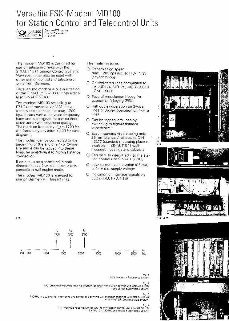
Versat i leFSK-ModemMDlOOfor Station Control and Telecontrol Units
A 200í/ . "'-"-ter *cr «sed501 A prr .r
The mode^n V1D10Q .5 desigred foruse on telecontrol Imks with theSINAUT1 STi Siation Control System.However, it can also be used withother staiion control and telecontrolunits from Siemens.
Because the modem ¡s put m a casingof the SIMATIC1 55-100 U it fies exact-ty to SINAUTST100.
The modem MD100 according toITU-T recommendation V.23 has atransmission channel for max. 1200bps. It runs within ihe voice frequencyband and is designed for use on dedi-caied lines vviíh te'ephone quality.The médium frequency (fj ¡s 1700 Hz,the frequency deviation ± 400 Hz (seediagram).
The modem can be connected to thebeginning or ihe end of a 4- or 2-wireline and it can be tapped into theselines. by switching it to high-resistanceconnection.
If data is to be íransmitted in bothdirections on a 2-wire line this is onlypossible in hatf dúplex mode.
The modem MD100 is licenced foruse on Germán PTT leased lines.
i r
The main features
O Transmission speedmax. 1200 bps acc. to ITU-T V.23(asynchronous)
O On dedicaíed lines compatible 10i.e. MD124, MD125, MDB1200-01.LGM 1200H1
O Type of mudulstion: binary fre-quency shift keymg (FSKJ
O Half dúplex operation on 2-wirelines or dúplex operation on 4-wirelines
C Can be tapped into lines byswitching to high-resisíanceimpedance '
C Easy mounting via snapping onto35 mm standard rail acc. to DIN46277 [standard mounting place isavailable in SINAUT ST1 wall-mounted housings and cabineis)
O Can be fully integrated into the sta-tion control unit SINAUT ST100
O Low current consumption (65 mAíat 24 V d.c. supply voltage
O Indication of interface signáis viaLEDs (TxD, RxD, RTS)
1300 1700 2100
300 500 1000 1500 2000 2500 3000 3500 Hz
v 23 Modem - FreauenF.g
F-g 2.n waH.rrountea nous-ng WG02P logelher ,vi'.r- =-3f.cn ccn-fo' unil SiNAUT STlCO
ana oower s^ppiv oacit-up jmt
MD100 ^n a cabinei ior monnof-rg and control of a üf-r\,rg waier S'.a'.-Qn :ctje'.r.er wlh stat 'Of controljpil 5INAUT STiQO aran radio system
fg 4/.'a.i-rrouriea ^.OuS-ng (s.muar VVG11) .v.'n STai'C" ccrT^ci u"'! Sl^JAU^ STl ;5.
2 x riM 2 x MD1QO dnd power S^DOIV D<ICV.-JD ur-;[
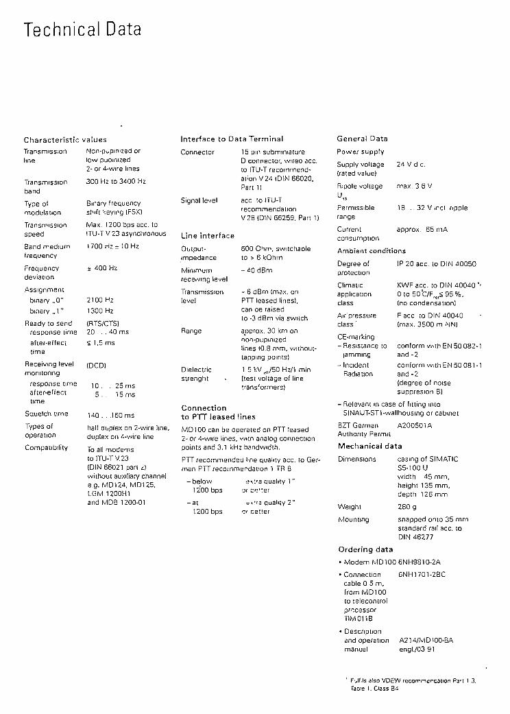
Technical Data
Characteristic
Transmissionline
Transmissionband
Type oímodulation
Transmissionspeed
Band médiumfrequency
Frequencydeviation
Assignment
bmary ,,0"
bmary ,.1 "
Ready to sendresponse time
after-effecitime
Receivmg levelmonitoring
response timeafter-effecttime
Squelch time
Types ofopera tion
Compaíibility
valúes
Non-pupimzed orlow puomized2- or 4-wire lines
3CO Hz to 3400 Hz
Bmary frequencyshifr keyíng (FSX)
Max. 12QObpsacc. toITU-T V 23 asynchronous
1700HZr 10 Hz
± 400 Hz
2100 Hz
1300 Hz
(RTS/CTS)20 ... 40 ms
< l.Sms
(DCD)
10 . . 25 ms5 . . 15 ms
140. . .160ms
half auplex on 2-wire line,dúplex on 4-wire line
To all modemstolTU-TV.23(DIN 66021 pan ¿íwithoui auxilian/ chennele.g. MD124, MD125,LGM 1200H1and MDB 1200-01
Interface to Data Terminal
Connector 15 pin subminiatureD connecíor, wirea acc.to ITU-T recommend-at 'onV24 (DIN 66020.Pan 1)
Signal level acc ;o ITU-TrecommendationV 28 (DIN 66259. Pan 1)
Line interface
Output- 600 Onm, switchableimpedance to > 6 kOhm
Mínimum - 4Q dBmreceivmg level
Transmission - 6 dBm (rnax. onlevel PTT ¡eased lines).
can oe raisedto -3 dBm via switch
Range aoprox. 30 km onnon-pupmizedlines lO.S mm, without-tappmg pomts)
Dielectric 1 5 kV^/50 Hz/1 minstrenght « (test voltage of line
trans'ormers)
Connectionto PTT leased lines
MD100 can be operated on PTT leased2- or 4-wire lines, wiin analog connectionpoints and 3.1 kHz bandwidth.
PTT recomrnended l'ne qualiry acc. to Ger-mán PTT recommendation 1 TR 8
-below oxr'a auahty 1 "1200bps or be'ter
-ai -«va quahty 2"1200 bps Of ceiter
General Data
Power supply
Supply voltage 24 V d c.(rated valué)
R;pole voltage max. 3 6 VU.
Permissible 18 . .32V,rc l ripplerange
Current approx. 65 mAconsumption
Ambient condítions
Degree of IP 20 acc. to DIN 40050proiection
Climaíic KWF acc. to DIN 4Q040 'application 0 to 50t/F,B< 95%,class (no condensation]
Air'pressure F acc. :o DIN 40040class ' (max. 3500 m NN)
CE-markíng- Resistance to conform wi;h EN 50 082-
jamming and -2
- Inciden! conform with EN 50 081 -Radiation and -2
ídegree of noisesuppresion 8)
- Relevant m case of fitting míoSINAUT-STl-walIhousmg or cabmet
BZT Germán A200501AAuthonty Permit
Mechanical data
Dimensions casmg of SIMATICS5-100Uvvidth 45 mm.height 135 mm.depth 126 mm
Weight 280 g
Mounting snapped onto 35 mmstandard rail acc. toDIN 46277
Orderíng data
• Modem MD100 6NH9810-2A
• Connection 6NH1701-2BCcable O 5 m,from MD100to lelecomrolpr~cessorTIM011B
Descnptionand operationmanual
A214/MD100-BAengl./03 91
F'jIMs also VDEWfecorrmefcation Pa't 1 3.Tabie 1. Class B4

SIEMENS
SINAUT LTOPLine Transformerwith Overvoltage Protection
Description
LTOP2Line Transformer withQvep/ottage Protection
OPMOvervolíage
Protection Modul

Une Transformar with Overvoltage Protection
Auíomation ¡slands are being increasingly ¡ncorporated into networks, where thisnetworking is currently still being carried out to a large extent using modems on prívatetelephone cables. However, metallic unes are highly sensitive to the coupling-in andcarry-over of external potentials. Coupling-in oí external poíenííals may be ¡nductive orcapacitive, e.g. as íhe result of lighíning. Direct galvanic coupling is also possible as aresult of insulation faults.
LTOP limiís interference voltages and overvolíages to a non-critical level. The floatingtransformar provides electrical isolation in addiííon, íhus preveníing potentíal carry-overonío other secíions of the line.
LTOP protects persons and investments and is thus an indispensable proíecííve elementin prívate telecontrol networks.
The most important features
• LTOP suppresses overvoltages down to acceptable valúes before they reach íhesensitive electronics.LTOP electrically segmenís the neíwork; the carry-over of external potenííals isprevented,
• LTOP limits the damage caused by an overvoltage effecí to the affected segment.• The protective elemenís are fitted on a plug-in OPM overvoltage proíecíion module.
The OPM can be replaced without interrupíing the telecontrol line.
Design
The protective concepí comprises a combination of componenís whose functionssupplement one anoíher (Fig.: Block diagram oí a LTOP unit):
• Overvolíage suppressors filled with inert gas as coarse protection (G1, G2)• Inductors which limit ríses in current (L1, L2)• Metal oxide varistor as fine proíection (voltage-dependení resisíance; R1)
Transformar for elecíríc decoupling (T1)Suppressor diode to limit íhe secondary voltage of the transformer (V1)
Modem
Block diagram of a LTOP unit LTOP2 design (plan view)
ATD OG2S/LTOP- 11.98/e - 2 - C Siemens AG 1998 All Rights Reserved

Function
The combinaíion oí discharging and limiting components which are supplemented by theune transformar is superior to electrically-bound safety concepts.
The protective elements inside of an'OPM are greatly síressed during dischargeprocesses and are slowly destroyed. Therefore it is recommended to replace the OPMsevery one year. To be on the safe side within regions with frequent thundersíorms thisperiod should be reduced to about 6 months.
The LTOP versions
In one housing eiíher one LTOP unií is accommodated (= LTOP1) ortwo LTOP units (=LTOP2). The following figures show the design of both LTOP versions with íheirconnectors and adjustment switches.
fS>
2 1
O1 2 3 4
K>
¡0111 MX6
2 1 M 2 i '
I/^T-;K^
/•
w1 2 3 ¿ 5 S
LTOP1 (plan view) LTOP2 (plan view)
Schematic diagram of LTOP1 Schernatic diagram of LTOP2
Modem connecíion
X6
X2 !
i
2
ii J"4K
L
i^^^^^
i \1
RJ122 5 3 4
IV V.I
3¡
-J
1 2r3
,
14 LTOP1
Modem connection
X2 T
i
X6
21
HJ122 5 3 4
V(|H-*^ í
2
£^^^^t
/f
I
X1 T
í
r2 3
^1
14
ir;i ¿i|1
5 f
:, 1
^H=-
£
2 X3
•4 1
isS
^_j5 IT
t
OP2
Siemens AG 1998 All Rights Reserved - 3 - ATD OGS/LTOP - 11 93

Legend:
X1 Telecontrol line (screw termináis 1, 2, 5, 6)Ground (screw termináis 3, 4)
X2 2-W¡re modem connectionX2 -í- X3 4-Wire modem connectionX6 2-Wire/4-wire modem connection via RJ12-Wesíern connector; for direct
connecíion of íhe SINAUT ST7 modems MD1 and MD2 via the standardinterconnectíng cable (RJ12 - RJ12) which ís supplied wiíh these modems.
S1 + S2 Adjustment switches
Configuratíons
Several LTOP-housings can be connecíed íogeíher if necessary. The following examplesshow possible and meaningful configurations.
LTOPl
Telecontro! line
2-Wíre terminal unit
BzSTelecontrol Une
4-Wire terminal unit
2-Wire tapping point
Legend:
mm Une Transformer)
'f Overvoltage Protection
T Transmitter
R Receíver
LTOP2
Only modemwith integrated jfork transformere.g. MD!24orM02
Telecontrol Telecontrolline #1 line #2
2 x 2-Wire terminal uni t
Te(f
LTOP2
Te(
lecontrol Unírom/to mast
'
•I
.
•1mm
£•
i
5 # 1
Pr^
Modem
R / T|
leconírol line #2rom/to station)
Telecontrol line #1(f rom/to master)
LTOP2
LTOP2
Telecontrol line #2(from/to station}
4-Wire íapping point
ATD OG2S / LTOP - 11.98 / e 3 Siemens AG 1998 All Rights Reserved

Connection of the SINAUT ST7-modems MD1 and MD2
The following figures show the connection oí the dedicaíed line modems MDl und MD2.The connecíion to LTOPl resp. LTOP2 is made vía the standard interconnecting cablewhich is suppüed with the modems. This cable has RJ12-Western connectors at boíhsides.
Note
Instead of the modem MD2 shown in the figures also the modem MD2 which isintegrated in the TIM32 orTlM42 can be connected. In this case the connectionto the LTOP is also made via the standard RJ12-cable supplied with the TIM.
Please take care that íhe modem MD2 has the correcí line termination:
• Wiíh terminal unit and 1200 oder 2400 Bit/s: 600 Ohm
• Wiíh terminal unit and 19.200 Bit/s: 150 Ohm
• With tapping point: high-resistance.
Por more details see descripíion of MD2.
The modem MD1 doesn't need any line íermination adjustment.
| Important
Please take care that íhe switches S1 and S2 are ¡n the correct position 1 or 2 asshown in the figures!
Connection of a 2-wire terminal unit (via LTOP1)
X6
X2!
]2
• !
RJ122 5 3 4
~iY V!f 1 !
•kl
i£S^i
X1jn
2-wiretelecon-trol une
LTOP1 :
MD2: 2-wire terminal unit via LTOPl MD1: 2-wire terminal unit via LTOPl
O Siemens AG 1998 All Rights Reserved ATD OGS / LTOP - 11 98 / e

Connection of a 2-wíre terminal unit (via LTOP2)
Connectior
MD2
2tí
tf
X 2 1
i
RJ12 |
X6
2
i 1
iRJ12
iV"
!si i
^^£
^
-wireíleconoí une
£L_
X1
-4 — >-
T1
o !2
TT-—-C:
.Y2 3
1
t
45
1S2
'(— '
^
2 X3
ÍZS- ./f
L
6 IT
Í- '
OP2
X2 T
1 1-
MD1
RJ12|1
X6
2RJ12
2 S 3 -l
V¥ii
2 í•"jl*. *! 1 . 1 " "" rC '; i 21
ÜLj.4
2-wiretelecon-trol line
/
^ \-•.
• X-?. !
-4 fr-
i
. r
: ri,. ,
2 3 4 5
S2J
[—- '
~) X3
i
£
. jsj-£
f.
L^ •
5 1TOP2
MD2: 2-wire terminal unit via LTOP2 MD1 : 2-wire terminal unit via LTOP2
i of a 4-wire terminal unit or 2 x 2-wire terminal unit
MD2
RJ12
X2 T
l k
1
X6
2 ' ' -•. 1 1
RJ122 5 3 4
V"rÜ*"11 *
M] 2
4¡sf--
4-wiretelecotrol lin
/\
X1 1
*-
j. •
H23
|
4-L1
2 !JJ>*H1-
i
t f4-5
LJ1-g ^
1 íS2j
£
2 X3'
i
'Sí/%_j
6 ITOP2
MD2: 4-wire terminal unit via LTOP2
2-wirícontr2-wirccontr
X2 !
i
MD2
RJ121i
X6
2 - • • • -
- • .( 1
RJ122 5 3 4
w 10 S -r-2
""" ""tr**1*"*! " ' i-"í_ *-*rC-
^" ffS^.
3 tele-3! line3 tele-D! une
4 -F
X1 !
|
f-]* *"
L;
;.-
IA2 3 4 5
t iy• ^~
1
£
¡
2 X3
-• i
"/
j¿
1
6 I'
¥2
FOP2
1
t
t
MD2: 2 x 2-wire terminal unit via LTOP2
ATO OG2S / LTOP - 11.98 / e © Siemens AG 1998 All Righls Reservetí

Connection oí a 2-wire tapping point
2-wire tele-control line #1
2-wire tele-control Une #2
MD2: 2-wire tapping point via LTOP2
Connection oí a 4-wire tapping point
4-wteleline
X2 !
' >•
MD2
RJ12
*~ .''*'. X9
2 . -V
RJ122 5 3 4
íVVí-1
- :— li— i *í " | ;' .-T"-f¡*^ ,; . ¿ •,— •*-}_-
í 2l íí• S1 j S2í w 1 j ¡ O £. i
i
S4-
recontro
£
X1 1
— »•
r23
14 5
| |y-4 —
^
2 X3
- 1
^^nOP2
X 2 !
11.2
X6 RJ122 5 3 4
-U 'YÍ <i1 2||S1J
±S/f
1
X1 ,r
2 3
4Í1
2 Í
JJ^XCl!
1
4 5
1 j
..§?J
^
2 X3
-< i
±z¡/?
_J
6 n
— -1 ^L_
'OP2
4-wiretelecontrolline ¥2
MD2: 4-v/ire tapping point via iwo LTOP2
¿í Siemens AG 1998 All Rights Reservad - 7 - ATD OGS / LTOP - 11 98 / e

Connection of the modems MD100, MD124 and similar modems
The íollowing figures show the connection of the dedicated line modems MD100 undMD124. The connection beíween modem and LTOP1 resp. LTOP2 is made via a two- orfour-core cable or single cores.
Note
Insíead of ihe modems MD100 and MD124 shown in the figures also any othermodem for dedicaíed lines can be connected.
Please take care that the modems MD100 or MD124 have the correct line terminaíion incase they are connected to the end of íhe line (600 or 150 ... 450 Ohm) or in case íheyare tapped in (high-resistance). For more details see descripíion of the MD100 resp.MD124.
Importan!
Please take care that the switches S1 and S2 are in the correcí position 1 or 2 asshown ¡n the figures!
Connection of a 2-w¡re terminal unit
2tt
MD100MD124
R / T
X2-,
I h
X6
2
i — f
¿
ü"
-wireslecon•oí íine
£
1 L
RJ122 5 3 -í
iTVV.2]
1
X1 1 2
.-^ — *-
r3
I
t
,
14
1
J
LTOP1
tt
MD100MD124
R / T
X2!
i >•
X6
21
RJ122 5 3 4
IV~ ji*^*" í
si_
£^^^^^t
•wireeleconrol Une
/*\
X1 ,
^ ^
^
í¿
i
1(J
231
Ij
T4
1
J
5 i
.,-• — •"•
l_4 ,
^
2 X3
< •
)Z '
^_J
5 I T OP2
MD100/ MD1¿4: 2-wire terminal unit via LTOP1 MD100/ MD124: 2-v/ire terminal unit via LTOP2
ATD OG2S/LTOP - 11.98 /e '£ Siemens AG 1998 Al! Rights Reserved

Connection oí a 4-wire terminal unit or 2 x 2-wire terminal unit
X2 !
i
MD100/MD124
R T
X6
1
RJ12
2 5 3 4
i" Í !~^t-+^*i "
aiS1 ¡
M— I
¿*S*;
4-wire;e!ecotrol lin
/
^ j-
" X1 i
—
r123
r
i2 ^
-lU-C-
í
14 51
^i-
1S2
¿
2 X3
i
/f
.U
6 ITOP2
2-wirecontrc2-wirecontrc
R
X 2 n
MD124
/T R/
X6
2
RJ12
2 5 3 4
!V~í r T1
1 >*-P-- 2|[S1J
£. n'
tele-I Une íteíe-I line í
^• L_
1xt 1
1
n-J
r2 3J_
T :4 5Iy
^ frÍ2
1JÜL
£
T
2 X3
i
'. 4
^i
6 rrOP2
MD100/MD124: 4-wire terminal unit via LTOP2 MD124: 2 x 2-wire terminal unit via LTOP2
Connection of a 2-wire tapping point
2-wirecontra
MD100MD124
R / T
X2 !
-
¿¿^a2 .-
í :"M ^
RJ122 5 3 4
i¥-¥íi
2 í
"P**^i-" iT^c:S 2¡- ,!
f±S^
tele-line #
£. I
X1
,- *-
; .- •
n2 3 4 5
I |U
1 ¡
^
2
1 k-
±í
/X
|.
6 IT
-4 ^~
OP2
2-wire tele-control line #2
MD100 / MD124: 2-wire tapping point vía LTOP2
C Siemens AG 1998 AII Rights Reserved - 9 - ATD OGS/LTOP - 11 98. e

Connection of a 4-w¡re tapping point
d-W
teleline
*2l
<
MD100/MD124
R T
•-
X6
21
RJ122 5 3 4
;V2Í
,§l.j
is^
recon tro#1
4 .* L_
X1 ,
— *•
r2 3
Y1-"--—i
2 !* -^iT^1_LJ— ***& —
* .•
14 5
T~ry•4
1 IJ32]
*
2 *3
•
S¡
. 4f
_|-
6 ITOP2
X2- ,
i
i12
X6 RJ122 5 3 d
i tiYJí í
í 2|
1§U
i
' 5/t¿
l_
X r1r
23
j¿.1
2 !1 =-^-*H_-
•
145
1 !.JL2J
i
2 X3
- 1
. /f_J
6 IT
— *-I — -y—
OP2
4-wiretelecontrolline fí2
MD100 / MD124; 4-wire tapping point vía two LTOP2
Overview of the adjustments of the switches S1 and S2
The following two tables give a summary of the possible adjustments of íhe switches S1
and S2. You will find ihese tables also as sticker on the LTOP1 resp. LTOP2.
SIEMENS6NH9- -3C11
LTOP1 AS:01 CE
2W 2v^ire 2DrahtP Point Endstelle
Einstellung / Position Si
für / for SINAUT-Modems
S1
MD100/MD124
2W
P
X2
1
MD1
2W
P
X6
2
MD2
2W
P
X6
1
iI
I
!
SIEMENS6NH9821-OBC12
LTOP2 AS:01 CE
2W 2v/ire 2Draht4W 4wire 4DrahtP Point EndstelleM Multi- Stafíelstelle
point
Einstellung / Position SI + S2
für / for SINAUT-Modems
S1
S2
MD100/MD124
2W
P
X2
1
1
2W
M
X2
1
2
4W
P/M
X24-X3
1
1
MD1
2W
P
X6
2
2
MD2
2W
P
X6
1
T
2W
M
XS
1
2
2 x2W
P
X6
1
1
4VV
P/M
XS
1
1
ATD OG2S / LTOP - 1 1 98 / e - 1 0 - Q Siemens AG 1998 All Rights Reserved

Ordering data
LTOP1
LTOP2
OPM
LTOP1 line transformer with overvolíage proíecíion withone built-in OPM overvolíage protection module
LTOP2 dual line íransformer with overvoltage proíectionwith 2 built-in OPM overvoltage protection modules
OPM overvoltage protecíion module, plug-in(pack of 4)
Bestell-Nr.:6NH9821-OBC11
Bestell-Nr.:6NH9821-OBC12
Bestell-Nr.:6NH9821-OBBOO
Technical data
Transmission paths
Transmission ratio
Transmission range
Frequency-dependentAttenuation
Insulation resistance
Test voltage
Impulse strength
Nominal impulse dischargecurrent ¡sn (8/20 us)
Output voltage limitation at isn
Telecontrol line connection
Modem connecíion
Mounting location
Dimensions (h x w x d)
Weight
Prívate coiled or uncoiled teleconírol lines
1 : 1 ; ± 5 % (e.g. 600/600 ohms within voice (requency band)
300 Hz to 35 kHz
Attenuation
[dB]
0,2
0,8
0,9
1,0
Frequency Transmission raíe [bit/s]
[Hzl MD100 MD124 MD1 MD2
1300... 1200 1200 1200 12003300 2400 2400 2400
960014400
5200 ... 48008400
10400... 960016800 ;
20800... 19200 9600 '30600 19200 :
> 2000 iviOhm
4 kV, 50 Hz, 10sec.
6KV/2 Jacc. to EN 60 099-1
5kA
appr. 15 V
Screw termináis X1Cross-section 0,2 - 4 mm2 with soüd conductorsCross-section 0,2 - 2,5 mm2 with stranded conductors
Screvv termináis X2 and X3 (see XI for cross-section)or X6 (RJ12 socket for Western plug)
As near as possible to the cable inlet to the building
90 x 75 x 1 10 mm
LTOP1: 300 g
LTOP2: 320 g
OPM- 10 g
Degree of protection IP20
Assembly DIN rail TS35 (35 mm; EN 50 022)
-, Siemens AG 1998 All Rights Reservad - 11 ATDOGS/LTOP - 11 93 . 'a

Anexo Pag. 203
E.- Hojas de Datos de los equipos que sé pueden utilizar

ií Letfei Irartsrfitóer"5O8-45 SepiB^
Integral Mounting
Pernote Mounting
Key Benefits
.-wo-Wire DesignTwo-Wire design eliminates needfor Une powcir at the tleld transmitterand saves on costs for Associated hardware. Can be. madc intrinsícallysafe when oowered from an approvcd
Rugged Cc^tructionNo moving r;recalibi'aci. '.'•-"
,. ¿ deteriórate or breík down. No routine cleaning or• •-••a.ry. Rugged construction resist-S r.nrrosi Xi'id
Measurement ReliabilityNo calibratioa shifts due to chan¿ .5 in temp^i\ "urc or material densities.CotQ-Sh.ieldnicircuitr3T ensures depende.' Tr.o^uremenr.s regardless of
on the sensing eleme.nt or buik'.- " "> the vesseí wall.
Proven PerformanceBased on technolog>- thatKa¿ '^ccn used successíull' at '^:'-^>- planes forover a decade,
The Universal™ IIcontinuous level trans-
mitler provides dependabielevel measurements ¡n allkinds of process liquids,slurries, granulars, andinterfaces.
Drexelbrook's Universal01 IIlevel transmítter offevs in-creased reliabüiiy, lo11-" •-v-irir'--nance and intrinsicaJ' •design.
Field-proven RF/Admittantechnolügy ensures depci.d.-level measuremenis in. a wia&range of conducciviries, reg'ard-leñfl ofcoatings or producebuild-up t;n the sensor. Calí-bration is not affíct^H hyvariations inmaterial dens.-J. .or changes in r,emp=r^tury.
The two-wire, dc-poweredelectrón i es can be remo ce tymounted up to 150 feet froche sensing element, or i¿rally moxinted with íhtíing elemenL All 1: "and sifi'nal wires are .cally safe wheii used wi:approved power supply.
With the most comprehe.Une of standard sensing em-"-r'.'.'-' ir r"h.e industry.
our
TM: Tradenarae of Drñxelbrook fínginr-eriní, '>

TypLai Systems-•-Ct-E '-C. : 533 2 <M3¿i
7 ~ "^
UodslNumdcr
508-47-5
• .'. 505-45-13 '"• . .(siamés) • .'
ñfiR-45-25(ccnducii.ig
SOS^^-TTiV'"^ •'' • (granularse •
: *£ —6-5
ui'.ftf fu-aj
processTemp/ProssRating
lOOU psi *5 13G"F:6a 3ü/ tt 37*CJ
SCO os; •&• 300'1C Í3-1 Bar '5? MS'Ct
1GOO psi © '.OG .FTíes BaF « 37*0*5CO psf © 25Gcr (3A..Baf l»"V2l)1.C>".
1000 os «' 100"F 1.58 Bar »3> j/°C)500 poi £ 300*P Í34 Bar « 148*C|
::í: >;;fe^ "-. .f A^>'r-^:
Tuno o=>: 'á1 lüü5F («a Bar '£ 37CC).Oup,, y .aOF ^ Bdf '§- 1-1 C)
Sensor Dlmensions
'..66-inch O.D Cono.i'U rt moü ifi m)
5/J'e-incfi O.D, •t . l;00-ft;máx fSO'm) .
OSo-inch O.D.•1ÜÜfl.'-:líixí1'31 m)
Inserlion lenylli
;,\:."íf-ii%ax [55-rrí)' -*v,*7¿ ' .lrjssítlc?o ¡QrtgtÍTr'
.S4-inch O.D.20 fl max fo miInsertion lenglh
Sensor M uintingDEmenei ms (2)
1-2--.CM
3/4-ínch •
NPT
§¿yp;-:|;
Sensor Mataríais ofConstruclfon (U)
•
TrC covcrca radC.S. or S.S Conc. Sniylo
C.'J. -j; S.S. mouPting
"X" covererf-ftex cabía, í. 7
PFA enverno HRX cnbltíS.S. rriountir^
•':¡;?&S| -;"X' tIOyfiftíQ 'Qd
S.S. mour.hng
l. =3ch sysíem indutJesfileci'onic unnand sñrsor. {ConnecTirg cable inctudea wth re.Tiole aioununn.) 2. Plangsrrountings opl:onai3. "X" is a fluorncaíDon-rype insulation. " Remote eleciionics and sensor.
Specif icat ions
A. PQWBT requíremsni; 11.5 w 50 VDC (Foriritnnslc salsty. sae "O" balow.j
8. Inpul range: 408-8202: 3.75 lo 40.000 pf.¿08-8332; 8 lo óo.OOOpF.
C. Outpul ranga: 4-20 mA. Currgnt Hmit ai 28 mA.
D. Llnaarltr- = O 25% of full scale.
E. Load resistente:VM 5.5- (i.e.. max 625 9 2¿ VDC).
*
/: vs = puwer supply vonage.
F. Temperaíure eríecl: ± 025% of full scale per30° F or ± 0.10 pF, whichever ¡s larger.
I. Rejpon»8 to Siep Changa: 20 millisaconos ita.(to 90% ottinal valué); adjusiable 0.5 to 30seconds available with tlfr.e dftlay (std )
J. Fall-Safe; Fíela aüjusiaole. Low-Lavsl Fail-Safe ('LLf:s;std. Alsocalled direcíaciiriQ becausscurrent incrsases as íhe level Ulereases, HJQft-
ll-Safe (HLFS). Also callad reverse actingcurrent decraases as level íncraasas.
G. Suppíy voltagafrom 11.5 toSOvdc.
; 0.2% oí íull scale max
H. Erfect of l&afl feUainct: 0.2% of íuil scala or:ass lof full rsslsranca ranga ai 2d VDC suouly.
K. Amblintlimparaturi; - 40 io 170°F(-40
L. Callbratlon Adjunmtnü: Siap Zero, Fine Zero,fírap Span, Fine Span. Time Oeíay
M. LowtK pírmhlíd rwfcdancí (sarwJng elamenllo ground): 100KO
H. Sintíng Elimint coatlng iftid: Max errorfor 2000 ohms-cm. product buildup ot i/i6'{2mm)thiciíoníypical sensino element.408-8202-1 — 1.5'(38mm)408-82320 — 0.7'{T8mm)(urror is O1 whsn coatlng is longer thana.^íSSmm) for 406-8232). Consult factory foroiher modflls.
0. Intrlnsic SalBty; Se- .Intrinsically sate for C:ass. w.-t..,.-, A,B:C anu CC¡3SS II Groups E.F and G (0¡v. ' antí 2}Also includes. EEwa Ilü ¿one O
asáronles 3nd slgnal v/ires: r ; CSAapproved intrinsically saiq for Class I Grcups A,3,C and D, Class II Groups E,F and G (Oiv -powsrsd by an intrinsicaiiy safe power sur,h /.Non-incandiva for Class I Groups A.B.C ano D;C¡ass II Groups £,F a^o 5 (Div. 2}.Aíso ¡ncluííes, £Ex!a IIC. 2one 1 whsn pov/arsa'rom an intrinsically safe power source.
P.HousIng: Ñama 1. 3, 4. 5 and 12. F,MAopfovsd Cxplosionurooí Jor Class I. GroupsA.B.C.Ü, Div. 1, and dusi-ignitionproof íor ClóíS 'Groups E,F.GtOtv. 1.Also incí'Jdes, I.P.S5, (orotactsd against dusí antív/arerfromnazzle).
NotoCúntlnuQus fevel icsasminsís are a/so availxble\5 'stmrt' transmirters wiíh Honeywe// orHART
protocols.
DREXELBROOK
An ISO 9001 Cert/fied Comp
509-45-A5-94-251
Prnted in USACrsxéibrook S
Cccyrigl-: 1994g Company
World Hesdquarten: Orexelbrook Engineering205 Korth Valley Road, Horsham, PA 19CW4 U.S.(Tel) 215/674-1234, (Fax) 215/674-2731
Europe Headquarlen; DrexelbrooK InstrumenteBedríjvencentnjm Reda, Waalreseweg 17,5554 HaVaiKenswaard, NetherlandslT,¡) 4902-89298, (Fax) 4902M7933
:^3rters; Nihon Drsxslbrook, Sankae~- 29-<í2Taitoh2-ChromeITa¡ioh-'<L
', (Fax) 33-833-2546

Table of Contents
SECTION 1 - INTRODUCTION..... ......... . ....................................... ...... ...................... .......'... 11.1 System Description ............................... . ...................... . ................ . ....................... . ..... 11.2 Models AvaMable ........ ............... .. .................. . .............................. . ........................ . ..... 2
1.2.1 Electronic Chassis ... ......................................................................................... 21.2.2 Housings .......................... . ....................... .... ............................. - ........................ 21.2.3 Sensing Elements... ...... ..... ........... . ....................... . ...................... . ........ - ........... 31.2.4 Connecting Cables . .................. . ......... . .............................................................. 3
1.3 Technical Specifications ..................... . ................................. .... .................... .. ..... . ..... 31.3.1 Electronic Unit .. ......................................... . ......... .. .............. . ............................ . 31.3.2 Three-Terminal Cable ........... . ................................................................. . .......... 41.3.3 Sensing Elements ................ . ............................................................................. 5
SECTION 2 - THEORY OF OPERATION ............ . ......... ................................................. .... 62.1 Electronic Unit ................................................................................................ . ............ 62.2 Sensing Elements. ................. . ............ . .............................. . ......................................... 82.3 Connecting Cables (Optional) ................ ... ................. ... ............................................. 9
SECTION 3 - INSTALLATION . ..................... . ............... ... ................................................. ..103.1 Unpacking ................ . ....... .......... ...................... . ..................... . ............ . .............. ... ..... 103.2 Mounting the Electronics. .......................... ... ............................. . ......... . ........... . ........ 103.3 Mounting the Sensing Element ...... ... ......... . ........................................................ ..... 113.4 Wiring the Electronic Unit ........ , ....................... . ........................................... . ............ 11
3.4.1 Ground Wiring .......... . ..... . ................................. . ............................................... 123.4.2 Ground Wiring in Fiberglass Housings .............. ... ............................. . ........... 12
3.5 Sensing Element Connections (Remote System) ........... . ....................................... 143.6 Sensing Element Connections (Integral System) ................... . ................... . ........... 153.7 Intrinsic Safety Barriere .......... . ........... . ...... . ................................................... .. ......... 15
SECTION 4 - CALÍ"'. CATIÓN ............................................ . ................................. . .......... ....174.1 Controls and Müjustments .............. .... ........... . .......................................................... 17
4.1.1 Zero and Span Controls......... ............ .... .......... . .............. .... ............................ 174.1.2 Time Delay Control and Loop Current Testpoints ....................................... 174.1.3 Below-Chassis Adjustments ............ . ............ . .................. . ................. .. .......... 18
4.2 Start-up ..................... . ................... . .................. . ................ . ................................ ......... 194.3 Calibration Procedures ......................................................................................... .... 20
4.3.1 Calibration of Flush Mounted Sensing Elements ......................................... 204.3.2 Proximity Applications .................... ....... ............................. . ........ .. ................. 214.3.3 Interface Applications ............. .... ..................... . ....................... . ...................... 22
4.4 Secondary Calibration Standard .. ............. ..... .......................... ... ............................ . 254.4.1 Recording Calibration Data ....... .............. . .......................... . ........................... 254.4.2 Recalibration .......... ..... ............. .... .................................................................... 25

SECT1ON 5 - ACCESSORIES 265.1 Setcon 265.2 Power Supplies 265.3 Meters - - 265.4 Meter/Power Supply/Setcon 275.5 Microprocessor Receivers : 27
SECTION 6 - TROUBLESHOOTING 286.1 Introduction 286.2 Checking the Electronic Unit. 28
6.2.1 Operation Check. ..286.2.2 Drift Check 29
6.3 Checking the Sensing Element 296.4 Checking the Sensing Element Cable 316.5 Checking the Two-Wire System Loop 326.6 List of Some Possible Problems and Causes , 336.7 Factory and Field Service Assistance 34
6.7.1 Telephone Assistance 346.7.2 Field Service 34

SECTION 1- INTRODUCTION
The ¡nstructions in this manual are for theDrexelbrook 508-4X-XX Series Universal IIsystem for leve! measurement ¡n liquids,slurries, interfaces and granulars.
1.1 System Description
Each Drexelbrook 508-4X-X Universal IIsystem Consists of a 408-8200 Series two-wire, 4-20 mA electronic unit and a 700series sensing element (probé). Most 508-4X-XX Universal II systems are available ineither integral or remote appiications. A380 series connecting cable is also suppliedfor remote systems.
The system model numbers indícate theapplication where they most often will beused;
508-45-X: For conducting liquids508-46-X: For liquid/Iiquid interfaces508-47-X: For insulating liquids508-49-X: For granular solids
The final digits in the system mode! numberrefer to the type of 700 Series sensingelement used.
The 508-4X-X is an admittance-to-currenttransducer. A change in leve! produces achange in admittance which results in achange in current. It is termed a two-wiretransmitter because the same two wiresused to power the unit also indícate thechange in level (4-20mA). See Figure 1-1.
(1) INTEGRAL SYSTEW
a) GROUNOED SlGNALWIRE LOOP
4-20 mA
25 FT. ( T Y P ) .r 150 FT. MAX.
SERIES 401-13-XX• POWER 5UPRY
Ip1
OPT10NALSAHTY W«£B
— -JL,E-
OUHDBUS
)n ..B-
T-3 (2) REMOTE SYSTEM
b) FLOATING SlGHALWIRE LOOP
NONHAZARDOUS ' HAZAROOUS
408-8200-LM/1

1.2 Models Available
1.2.1 Electronic Chassis
The following ¡s a partiai list of the various408-82X2 Series chassis models available:
408-8202-1 — Basic electronic unitintended for use with insulatingmaterials, ¡nterfaces, and semi-conducting granulars.
408-8232-1 — Basic electronic unit(408-8200) internally connected foruse with conductive materials andcertain insulating granulars,
408-82X2-1 —Time delay optionincluded.
1.2.2 Housings
The 408-8200 Series electronic units areavailable in a NEMA 4 or explosionproofhousing. A "1" in the last position of theelecíronic unit number indicates chassisoniy, no housing. Example, 408-82XX-X1means chassis only. The standard housingmeets the following NEMA classifications:
NEMA1 General Purpose2 Drip Tight3 Weather Resistant4 Waterproof
4X Waterproof/Corrosión Resistant7 Explosionproof9 Dust/lgnitionproof
12 Industrial use: oü and dust-tight
1.2.3 Sensing Elements
The following sensing elements are mostoften recommended with a 508-4X-XXXsystem according to the application requirements. See Section 1.3,3 for detailed
specifications. This listing does not includeal! of the sensing elements available withthe 508-4X-XX series system. For ¡dentifi-cation, the last digits of the sensing elementmodel number are stamped into the mount-ing gland. If you have additional questionsabout sensing elements, contact the factor/or your local representative.
700-1-22 — Rigid sensing elementfor waterlike conducting liquids.700-1-24 — Concentric shield sens-ing element for waterlike insulatingliquids.700-1-34 — Caged sensing elementfor thick, insulating liquids.700-2-24 — Rigid sensing elementfor low viscosity conducting liquids.700-2-27 — Rigid sensing elementfor ¡nterface measurement whichinclude ketones and esters.700-2-37 — Rigid sensing elementwith a lower resistivity limit for inter-face measurements and thick con-ducting liquids.700-2-57 — Heavy-duty, rigidsensing element for most conductingliquid and ¡nterface measurements.700-5-18 — Flexible sensing elementfor agitated conducting liquids andfor granulars.700-5-19 — Heavy-duty, flexiblesensing element for highly abrasivemineral granulars.700-5-54 — Flexible sensing elementfor longer insertion lengths inwaterlike conducting liquids.700-202-23 — Rigid 3-terminal sens-ing element for short range spans ininsulating liquids and granular^.700-205-78 — Flexible sensingelement with slack adjuster for insu-lating liquids and granulars.
408-8200-LM/2

1.2.4 Connecting Cables
When necessary to avoid excessivetemperaturas and vibration, the electronicunit and sensing element can be connectedby a three-termina! coaxial cable.Drexelbrook cables are available in:
General Purpose: 380-XXX-12HighTemperature: 380-XXX-11Composite: 380-XXX-18 (first 10 feet hígh
temperature)
The XXX in the model number indicates thelength of the cable in feet. 25 feet is stan-dard (e.g. 380-025-12), but longer andshorter lengths are available. Cable canalso be purchased in bulk lengths with ter-mination kits. Consult factory for máximumrecommended lengths per specific applica-tion.
1.3 Technical Specifications
1.3.1 Electronic Unit (typical)
A. Power requirement: 11.5to50Vdc (For intrinsic safety, see "N"befow.)
B. Inputrange: 408-8202; 3.75 to40,OOOpF; 408-8232: 6to40,OOOpFwith 5 ft. of cable.
C. Output range: 4-20 mA
D. Linearity: ±0.25%.
E. Load resistance:Vs-11.5* (i.e. max 625 @ 24Vdc).
.02
*Where Vs = power supply voltage.
F. Temperature effect: ±0.25% of ful!scale per 30°F or ±0.1 pF whicheveris larger.
G. Supply voltage effect: 0.2% max.from 11.5to 50 VDC.
H. Effect of load resistance: 0.2% orless for ful! resistance range at 24VDCsuppiy.
I. Response to Step Change: 0.5-30seconds standard (to 90% of finalvalué)
J. Fail-Safe: Field adjustable. Low-Level Fail-Safe (LLFS) std. Alsocalled direct acting because currentincreases as the level increases.High-Level Fail-Safe (HLFS). Alsocalled reverse acting because cur-rent decreases as level increases.
Note: THERE ARE NO DEVICESTHAT ARE ABSOLUTELY "fail-safe"."Fail-safe" means that in the event ofthe most probable failures, the instru-ments wiil fail safely. "Most probablefailures" means such things as lossof power and most transistor andcomponent failures. If your applica-tíon needs absoiute fail-safe, abackup instrument should be installed.
K. Ambienttemperature: -40°to+150°F (-40° to 65°C) at 24 Vdc.
L. Calibration Adjustments: StepZero, Fine Zero, Step Span, FineSpan, Time Delay,
M. Lowest permitted resistance(bare sensing element to ground)causing 5% error in each model:
600Q- 8202- 8232
408-8200-LM/3

N. Intrinsic Safety: Sensing ele-ment and cable: Intrinsicaíly safe forClass I Groups A, B, C and D; ClassII Groups E, F and G (Div. 1 and 2).
Electronics and signa! wires: Intrinsi-cally safe for Class I Groups C andD, Class I! Groups E, F and G (Div.1) when powered by an intrinsicallysafe powersupply. Non-incendivefor Class I Groups A, B, C and D;Class II Groups E, F and G (Div. 2).
O. Cable Length: 150 feet máxi-mum.
P. Independence ofzero and span:±1% máximum.
Q. RFI Protection: Inherentwith unitagainst standard walkie-talkie inter-ference; 5 ft. standard distance withproper installation.
1.3.2 Three-Terminal Cable
A. General Purpose;380-XXX-12: .51" OD at largestpoint, 160°F temperature limit.
B. Composite Cable (first 10 feethigh temperature):380-XXX-18: .62" OD at iargestpoint, 450°F temperature limit for first10 ft. 160°F temp limit for remainder.
C. High Temp. Cable 380-XXX-11:.51" OD at largest point. 450°Ftemperature limit.
408-8200-LM/4

1.3.3 Sensing Elemente
Std. Mal ofMod. # Construction
700-1-22 TFE covered rod
700-1-24
700-1-34
TFE covered rodw/CS concentricshield
TFE covered rodw/CS cage
700-2-24 TFE covered rod
700-2-27 TFE covered rod
700-2-37 tnX" coveredrod
700-2-57 '"X" coveredrod
700-5-18 ~"X" coveredcable
700-5-19 Urethanecovered cable
700-5-54 PFA coveredcable
700-202-23 Bare316SSrod
700-205-78 *"X" coveredcable
OD & Mtg. .
Rod3/8" OD3/4" NPTConcentricshield1.66" OD1 1/2" NPTCage4.026" OD4" 150#flangeRod3/4" OD3/4" NPTRod.54" OD3/4" NPTRod.54" OD3/4" NPTRod.84" OD1" NPTCable5/16" OD3/4" NPTCable3/4" OD2" NPT •Cable.093" OD3/4" NPTRod1/2" O D1 1/2" NPTCable5/16" OD1" NPT
Temp.Limits
100°F300°F -
100DF300QF
100DF300°F
100°F450°F
100°F300aF •
100°F'250°F .
100°F .250°F .
100°F«250°F i
150°Fi
100°Fi300°F .
100°F i450°F i
250°F .
& Press.
@ 1000 psi@ 500 psi
@ 1000 psi@ 500 psi
@ 1000 psi@ 500 psi
@ 1000 psi@ 500 psi
@ 1000 psi@ 500 psi
@ 1000 psi@ 500 psi
@ 1000 psi@ 500 psi
@ 1000 psi@ 500 psi
@ 5 psi
@ 1000 psi@ 500 psi
@ 1000 psi@ 200 psi
@ 5 psi
Max Rec.InsertionLength
20 ñ.
20 ft.
19 n.
14 n.
12 ft.
13 ft.
20 ft
200 ft.
200 ft.
400 ft.
10 ft.
200 ft.
Sensing ElemeType
2-term. rigid
2-term. rigid
2-term. rigid
2-term. rigid
2-term. rigid
2-term. rigid
2-term. rigid
2-term. flexible
2-term. flexible
2-term. flexible
3-term. rigid
3-term. flexible
""X" is a fluorocarbon-type insulation.
408-8200-LM/5

SECTiON 2-THEORY OF OPERATION
2.1 The Electronic Unit
The electronic unit opérales on the bridgeprincipie with an ¡nternal high frequencysinewave oscillator providíng a stable mea-surement signal source. The instrumentmeasures the capacitance orthe admittanceof the sensing element (probé) in the pro-cess, For the direct acting mode, the outputof the ¡nstrument increases with increasingievel (or increasing capacitance/admittance).
Figure 2-1 shows a block diagram of a Uni-versal II Ievel transmitter with the operatorcontrols for zero level, high Ievel (span) andtime delay. The units are shipped in direct
acting mode (LLFS) and either 8202 (¡nsu-lating materials) or8232 (conductive mate-rials) mode.
The 408-8200 series has ¡mproved linear-ity and improved Cote-Shield performance.It afso has built-in RFI protection on the 2-wire input/output wiring, built-in adj'ustabletime delay and probé spark protection. Inaddition, the unit is compact enough to bemounted integrally with the probé and itshousing thereby eüminating the need forthe coaxial cable. Two test points areprovided for the insertion of a standardmilliammeter for measuring the loop cur-rent without breaking the current loopcircuit.
2-W1REINPUT
4 TO 20 mA
DIRECT/REVtRSEACTING JUMPER
CHASSS
fh
GROUNO SHIELD PROGECRN REO BUJE
Figure 2-1Block Diagram
408-8200-LM/6
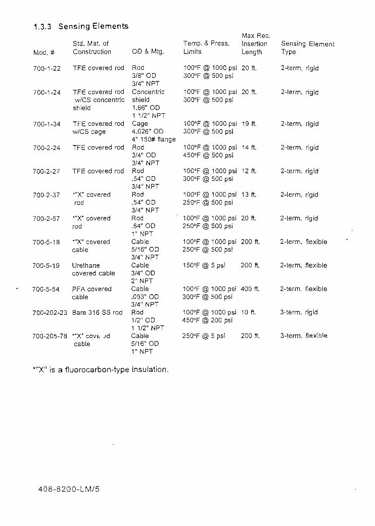
1.3.3 Sensing Elements
Std. Mat ofMod. # Construction
700-1-22 TFE covered rod
Max Rec.
700-1-24
700-1-34
TFE covered rodw/CS concentric
shield
TFE covered rodw/CS cage
700-2-24 TFE covered rod
700-2-27 TFE covered rod
700-2-37 *"X" coveredrod
700-2-57 *"Xn coveredrod
700-5-18 *"X" coveredcable
700-5-19 Urethanecovered cable
700-5-54 PFA coveredcable
700-202-23 Bare 316 SS rod
700-205-78 ""X" covt ¿cable
OD & Mtg.
Rod3/8" OD3/4" NPTConcentricshield1.66" OD1 1/2" NPTCage4.026" OD4" 150#flangeRod3/4" OD3/4" NPTRod.54" OD3/4" NPTRod.54" OD3/4" NPTRod.84" OD1" NPTCable5/16" OD3/4" NPTCable3/4" OD2" NPTCable.093" OD3/4" NPTRod1/2" OD1 1/2" NPTCable5/1 6" OD1" NPT
Temp. ¿Limits
100°F<c300°F g
1GOEF(c300°F g
100°F(c300°F (c
100°F(c450°F {c
100°F(J300°F (c
1GO°F{£250°F (c
100°F(c250°F (£
100°F(£250°F (£
150°F{§
100"F (c300°F d
100°F(5450°F (5
250°F (§
ii Press.
§ 1000 psi5 500 psi
§ 1000 psi§ 500 psi
§ 1000 psi§ 500 psi
§ 1000 psi§ 500 psi
§ 1000 psi^ 500 psi
^ 1000 psi§ 500 psi
^ 1000 psig 500 psi
g 1000 psiD 500 psi
^ 5 psi
D 1000 psiE) 500 psi
5 1000 psiD 200 psi
^ 5 psí
ínsertionLength
20 ft.
20 ft.
19 ft.
14 ft.
12 ft.
13 ft.
20 ft.
200 ft.
200 ft.
400 ft.
10 ft.
200 ft.
SensingType
2-íerm.
2-term.
2-term.
2-term.
2-term.
2-term.
2-term.
2-term.
2-term.
2-term.
3-term.
3-term.
Eleme
rigid
rigid
rigid
rigid
rigid
rigid
rigid
flexible
flexible
flexible
rigid
flexible
*"X" ¡s a fluorocarbon-type insulation.
408-8200-LM/5

SECT10N 2-THEORY OF OPERATION
2.1 The Electronic Unit
The electronic unit opérales on the bridgeprincipie with an ¡nternal high frequencysinewave oscillator providing a stable mea-surement signal source. The ¡nstrumentmeasures the capacitance or the admittanceof the sensing element (probé) ¡n the pro-cess. For the direct acting mode, the outputof the instrument increases with increasinglevel (or increasing capacitance/admittance).
Figure 2-1 shows a block diagram of a Uni-versal II level transmitter with the operatorcontrols for zero level, high level (span) andtime delay. The units are shipped in direct
acting mode (LLFS) and either 8202 (insu-lating materials) or8232 (conductive mate-rials) mode.
The 408-8200 series has improved linear-ity and improved Cote-Shieíd performance.It also has buiit-in RFI protection on the 2-wire input/output wiring, built-in adjustabletime delay and probé spark protection. Inaddition, the unit is compact enough to bemounted integrally with the probé and itshousing thereby eliminating the need forthe coaxial cable, Two test points areprovided for the insertion of a standardmilliammeter for measuring the loop cur-rent wíthout breaking the current loopcircuit.
2-WREINPUT
4 TO 20 mA
DIRECT/REVERSEACTING JUUPER
GRGUND SHIELO PROBÉCRN REO BUJE
Figure 2-1Block Diagram
408-8200-LM/6

'• *'-*>•

The coating must be electrically "long11 foríhis measurement to work perfectly. Howlong will depend on the thickness of thecoating, the capacitance of the sensingelement, the sensing element diameter, andthe frequency at which the measurement ismade. Generally, a coating of severa!inches to one foot is long enough not toproduce an error. Shorter coatings havesome error, but only a fraction of the lengthof the coating. For any one set of para-meters, the coating error is in inches, notpercent. A set of conditions that produces acoating error of one inch will always produce an error of one inch, regardless of thesensing element length or calibrated span.The bridge circuit allows spans as high as40,000 pF. This span increase permitsmeasurements in larger vessels and makesit possible to use sensing element withhigher capacitance in order to improve theinstrument's ability to reject the effects ofcoatings. A great advantage with this unit isthat, because of the two-wire transmission,it can be made intrinsically safe. This oftenremoves conduit and explosionproofrequirements, and eliminates safety hazardsto the ¡nstrument mechanic.
All of the above circuitry is fed from a con-ventional two-wire 24 Vdc, 4-20 mA powersource.
2.2 Sensing Elements
The necessary change of input capacitance/admittance is provided by a sensing ele-ment or "probé", which is -nounted in ornear the material being measured.
Sensing elements are available in manyforms, depending chiefly on the applicationfactors of temperature, pressure, insertionlength, and the characteristics of the pro-duct being measured; such as viscosity,coating, corrosión, conducíivity and dielec-tric constant. When these properties areknown, the factory will select the correctsensing element for the application.
Sensing elements are of two general types:immersion and proximity.
Immersion type sensing elements can bedivided into two general categories, "insu-lated" and "non-insulated".
Non-insulated or"bare" immersion sensingelements have a bare metal probé to sensethe product. These are commonly usedwhen the product being measured is non-conductive and not highly corrosive. SeeFigure 2-3.
1NSULATOR
BARE METAL,
GROUNO(2) Figure 2-3 CENTER ROD'Bare Sensing Element
Insulated immersion sensing elements havethe probé covered in an ¡nsuiating materialsuch as teflon. Insulated sensing elementsmay be used in applications measuring con-ductive or nonconductive producís. SeeFigure 2-4.
408-8200-LM/8

2.3 Connecting Cables (Optional)
GRCUNDCENTER ROD(
Figure 2-4Insulated Sensing Element
Proximity-type sensing elements are usedwhen it is necessary or desirable that thematerial being measured does not come incontact with the sensing element SeeFigure 2-5.
BARE METALPROXIUITY PLAÍE
GROUNOÍ2
3)COTE-SHIELDELEMENT
BARE METALCENTER ROOFigure 2-5
Three-Terminal Sensing Element(Shown with Proximity Píate)
For long insertion lengths or where head"clearance is a problem, flexible cableprobes are also available in both insulatedand bare metal models, as shown in Figure2-6.
In remote system applications, theDrexelbrook 508-4X-XX systems typicallyuse a three-tenminal coaxial cable to con-nect the sensing element to the electronicunit. The centerwire ofthe cable carnesthe change in capacitance signal from theprobé to the electronic unit, while the co-axial shield ¡s driven at guard potential(sometimes called Cote ShieldfTM]). Thepurpose ofthe shield ¡s to elimínate anycapacitance from the centén wire to ground.As a result, the cable capacitance does not¡nterfere with the capacitance signáis fromthe probé. There is no need for the elec-tronic unit to uzero out" the cable capaci-tance in orderto get a reüable reading.The shield also prevenís output errors dueto changes in cable capacitance caused bytemperatura. See Figure 2-7.
CENTER W1RE-(8LUE)
Figure 2-7 GROUND-Typical Coax Cable (CRN)
SHIELDWIRE
(RED)
INSULAÍOR ANCHOR
GROUND 2
THREAD FORANCHORING
Figure 2-6Flexible Cable Sensing Element
408-8200-LM/9

SECTION 3 - INSTALLAT1ON
3.1 Unpacking
Carefully remove the contents of the cartónand check each ítem against the packinglist before destroying any packing material.If there is any shortage or damage, report itimmediaíeiy ío the factory.
3.2 Mounting the Electronics
The 408-8200 Series system was designedfor field mounting, but it should be mountedin a Jocation as free as possible from vibra-tion, corrosive atmospheres, and any possi-bility of mechanical damage. For conve-nience at start-up, mount the instrument ina reasonably accessible location. Ambienttemperatures should be between -40°F and140°F. (-40°and 60°C). See Figure 3-1.
6 5/8
JL_
6 3/8
Figure 3-1BTypical Mounting Dimensions
(Remote Unit)
NPT OROPTIONAL
Figure 3-1ATypical Mounting Dimensions
(Integral Unit)
408-8200-LM/10

3.3 Mounting the Sensing Element 3.4 Wiring the Electronic Unit
The mounting location for the sensingelement (probé) is often determined by theplacement of nozzles or openings ¡n thevessel. The sensing element should not beplaced in a fill stream. When there is nosuitable location inside a vessel, an exter-na! side arm or stilling well can be consid-ered.The following sensing element mountingand ¡nstallation instructions should befolíowed so that the equipment will opérateproperly and accurately:
A. In applications requiring an insulatedsensing element, use particular care during¡nstallation. There is always the danger ofpuncturing the insulating sheath, especiallywith the thin-walled, high capacitanceprobes.B. Sensing elements should be mounted insuch a manner that they are not in the directstream of a filling nozzle or chute. If this isnot possible, a deflecting baffle should beinstalled between the probé and the fill.
C. Do not take a sensing element apart orloosen the packing glands.
D. Tighten the sensing element with thewrench fíats nearestthe mounting threads.
CAUTIONAvoid using single-part RTV sealant in theprobé or instrument housing. The single-part sealants frequently contain acetic acidand cause corrosión of circuit components.Special two-part sealants (non-corrosive)are available. Consult factory for types ofrecommended two-part sealants.
The signal connections are made to thethree terminal block on the front of chassís.Due to the low power consumption of theinstrument, the wiring need oníy be lightgauge (e.g. 20 AWG). See Figure 3-2 forproper connections. Twisted shielded paircables are recommended for lengths over200 feet.
The cable from the sensing element isconnected to the black, four terminal stripon the back of the instrument chassis. SeeFigure 3-3. The cable connections arecenterwire (CW), ground (gnd), and shield(SH).
Only coaxial cables supplied byDrexelbrook Engineering Company shouldbe used to connect the transmitíer to thesensing element. Use of other cables canresult in unstable calibration.
408-8200-LM/11

EARTH-GNO.(TO
COtfDULETBASE
OPTIONAL)
POWER/SIGNALCONN.
OBSERVE POLAR1TYOF SIGNAL WIRE5.
TWISTED SHIELDEDPAIR (TYPICAL) ¿-10-32 SCREW
SHIELD W1RE IF USED. RECOMMENDEDON LONG SIGNAL LEAOS.
applied to íhe barrier will notexceed the barrier voltagerating, ¡f barriers are used.
3.4.1 Ground Wiring
The 408-8200 series trans-mitters have Radio FrequencyInterference (RFI) filteringbuílt into the unit, In order tobe effective, The electronicunit condulet (housing ) mustbe grounded to low imped-anee earth (ground) rod in thevicinity of the transmitter. Thevessel wall also needs to begrounded to reduce interfer-ence through the sensor. Ifusing a non-metallic vessel,consider concentrically-shielded sensors or external
Figure 3-2Power/Signal Connections
CAUTIONBefore using Intrinsic Safety Barriers, readthe manufacturers instructions for barrieroperation. Barriers supplied by DrexelbrookEngineering Company, and prewired to thepower supply, have already been tested forproper operation. See Figure 3-4.
The 408-8200 has a built-in current limiterwhich holds the signal current to a máxi-mum of 28 mA. Make sure that the voltageRFI filtering. Further, improvement is gen-erally obtained by placing the sensor cablein a grounded metal conduit and shorteningany excess cable. In particularly trouble-some RFI situations, additiona! RFI filteringmay be required. Contact the factory formore information.
3.4.2 Ground Wiring in FiberglassHousings
When the transmitter is mounted in a fíber-glass housing, be sure that an earth groundis carried through the fiberglass housingand put in contact with the "sprayed in"metallic coating on the inside of the hous-ing. This coating provides additional RFIfiltering. Additionally, the ground wireshould be connected to the transmitterground terminal. See Figure 3-2.
408-8200-LM/12

BLUE (CW)
RED (SH)
CREEN (GND)
COAXIALCABLE
REMOTE CABLE CONNECT10N
Figure 3-3Cable Connections to the Transmitter
MOUNTING ANOGROUNDINC STUDS
(MUST 3E LESS THAN ir?OIFFERENCE BETWEEN
GROUNDING STUDS AMOACTUAL EARTH—GROUND)
BUS BAR
TERMINAL TONONHAZARDOUSÁREA
BUS BARMOUNTINGTABS
EARTH-GROUNDCONNECTIONS
CAPTIVE COVERFOR TERMINAL
TERMINAL TOHAZARDOUS ÁREA(l.S. SIDE)
Figure 3-4Typical Intrinsic Safety Barrier
408-8200-LM/13

3.5 Sensing Eiement Connections(Remote System)
The cable connections to the sensing ele-ment are shown in Figures 3-5A and 3-5B.Do not connect the cable to the sensingelement until after the sensor has beeninstalled in the vessel and the condulethousing has been screwed on securely. Ifyour probé does not have a shield connec-tion, be sure to clip and/or tape the shieldwire at the probé end of the cable.
CENTERV/iRE
ÍBLUE)(PROBÉ CONNECTOR)
GROUNDV/IRE
(GRN)
SHIELO WIRE.MUST BE CUPPED
SY CUSTOMERFOR TWO-TERMINAL
PROBESCONDL'LET
Figure 3-5AThree-Terminal Cable Connections to
Two-Terminal Sensing Element
If spark protection is supplied (for specíalapplications, consult factory), use the fol-lowing instructions for installing the sparkprotector in íhe sensing element condulet:(See Figure 3-6.)
A. Attach the mounting link on thespark protector to the probé centerconnection screw.
B. Connect the green wire from thespark protector to the ground screw.
C. Feed the cable into the condulet.
D. Connect the cable center wire(CW) to the spark protector and theground wire (gnd) to the groundscrew as shown.
E. Connect the shield wire to theCote-Shield terminal (SH).*
*For sensing elements that Do not haveShield connections, clip the shield wire asshown in Figure 3-6.
CENTERWIRE
(BLUE)(PROBÉ CONNECTOR)
GROUNDWIRE
(CRN)
COTE-SHIELDWIRE
(RED)
CABLE CENTER WIRE(BLUE)
GREEN WIRE
SPARK PROTECTOR377-1-19
PROBÉ CENTERCONNECTION
PROBÉ
3-TERMINAL CABLEfO TRANSM1TTER
SHIELD WIRE(RED)
GROUND(GRN)
CONDULET
SHIELD WIRE MUST BE CLIPPEO BY CUSTOMER FOR3 TERMINAL SENSING ELEMENTS
CONOULET
Figure 3-5BThree-Terminal Cable Connections to
Three-Terminal Sensing Element
Figure 3-6Typical Spark Protection
(Remote System)
408-8200-LM/14

3.6 Sensing Element Connections(Integral System)
In an integral system, there ¡s no cable.Therefore, the connections to sensingelement are made direcíly to the electronicunit. Refer to Figures 3-7A and 3-7B.
JHO-9000-79
Figure 3-7AIntegral-Mount Sensing
Element Connection
Figure 3-7BIntegral-Mount Sensing Element
Connection with Spark Protection
3.7 Intrinsic Safety Barriers -Installation with DrexelbrookContinuous Instruments
A typical installation of a single intrinsicsafety barrier is shown in Figure 3-8. Asingle barrier installation is usually rated foroperation at 24-26V with a máximum of 80mA. The barrier will typically start limitingthe current at 26 mA. Drexelbrook recom-mends that a current-limíting, rather than atrip type barrier be used in the installation.The reason for this approach is that a trip-type barrier must be reset by breaking theloop power to reset the barrier. The inad-vertent tripping often occurs during calibra-tion. This condition does not occur with acurrent-limiting style barrier.
Single-Barrier Installations (Figure 3-8)
When using barriers, an important consider-ation is the overall loop resistance. Using astandard 24 Vdc power supply, the máxi-mum loop resistance is 1200 ohms. Each50 ohms in a loop uses 1 Vdc. A typicalDrexelbrook transmitter requires a mínimumof 11.5 Vdc, leaving 12.5 volts for the loopand a máximum load in the loop of 625ohms. All of the loop resistance must betotaled to determine the remaining resis-tance that can be used by a barrier. Usu-ally a "positive" barrier in a loop has aresistance of between 200 and 250 ohms,leaving approximately 400 ohms for oíherÍtems in the loop.
2-Barrier Installations (Figure 3-9)
In certain instances, it is desirable that twobarriers be used in an installation, such aswhen the signal is being fed to a micropro-cessor input card. A two-barrier installationallows the loop to float relative to ground,When this condition exists, it is very impor-tant that the loop resistance is checked tobe sure that sufficient voltage ¡s available
408-8200-LM/15

for correct transmitter operation. As shown¡n Figure 3-9, if two barriers are used, eachhaving an internal resistance of 250 ohms,there would be only 125 ohms available forall other devices. To gain additional resis-tance, change the return (negative leg)barrier to a lower voltage type, e.g. rating of+6V. Normaily the barriers have a resis-tance of approximateiy 12.5 ohms + 2V. Bylowering the voltage type, the overali effec-tive resistance would be 312.5 ohms, whichaliows an additional 312.5 ohms in the loop.
HAZARDOUS LOCATIONCLASS 1,11,111 OIV 1
,«n.5V 4-20 mA
NON-HAZARDOUSLOCATION
BUSBARLOAD
INTRINS1CALLY SAFE CIRCUIT
Figure 3-8Single Barrier Installation
HAZARDCCLASS
WIN"
INTRINSIO
US LOCATIONUl.lll D1V 1
11.5V 4-20 mAA A A-
^XMTR
1
vvY Y OF
1.5
\LLY SAFE
'TIONAL. LOAD
CIRCUIT
NON-HAZARDQUSLOCATION
BUSBAR INPUTn VOL -cerLS.B. -^
^-.- , ¿j " VV "X RETURN
BARRIER
EARTH GROUND
Figure 3-9Two-Barrier Installation
408-8200-LM/16
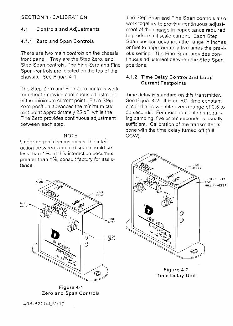
SECT1ON 4 - CALIBRATION
4.1 Controls and Adjustments
4.1.1 Zero and Span Controls
There are two main controls on the chassisfront pane!. They are the Step Zero, andStep Span controls. The Fine Zero and FineSpan controls are locaíed on the top of thechassis. See Figure 4-1.
The Step Zero and Fine Zero controls worktogetherto provide continuous adjustmentof the minimum current point. Each StepZero position advances the minimum cur-ren! point approximately 25 pF, while theFine Zero provides continuous adjustmentbetween each step.
NOTEUnder normal círcumstances, the ¡nter-action between zero and span should beless than 1%. If thís interaction becomesgreater than 1%, consult factory for assis-íance.
FINESPAN
The Step Span and Fine Span controls aisowork together to provide continuous adjust-ment of the change in capacitance requiredto produce ful! scale current. Each StepSpan position advances the range in inchesor feet to approximately fíve times the preví-ous setting. The Fine Span provides con-tinuous adjustment between the Step Spanpositions.
4.1.2 Time Delay Control and LoopCurrent Testpoints
Time delay is standard on íhis transmitter.See Figure 4-2. It is an RC time constantcircuit that is variable over a range of 0.5 to30 seconds. For most applications requir-ing damping, fíve orten seconds is usuallysufficíent. Calibration of the transmitter isdone with the time delay turned off (fullCCW).
TIMEDELAY
Figure 4-2Time Delay Unit
Figure 4-1Zero and Span Controls
408-8200-LM/17

After calibraíion is complete, a time delaycan be added, without affecting the caübra-tion, by turning the control knob clockwise.Occasionally, when the time delay is firstturned on, there is a temporary upset in thetransmitter output until the circuit settles out.Two testpoints are provided so that loopcurrent can be monitored without breakingthe loop with a standard analog or digitalmultimeter set to measure O to 20 mA.
4.1,3 Below-Chassis Adjustments
There are two adjustments in the chas-sis that are set by the factory and normallydo not need to be changed. However, ifnecessary, they may be reset by field per-sonnel. They are the fail-safe selector anda modification procedure for changing the408-8202 to a 408-8232.
A. Fail-Safe Selector
The fail-safe selector determines whetherincreasing or decreasing level will cause theoutput current to increase. It is a movablelink located on a printed circuit board on theinside of the chassis. See Figure 4-3. <
The instrument is supplied with the morecommon low-level fail-safe unless otherwisespecified. Low Level Fail Safe (LLFS)provides increasing current signal with in-creasing level. (See description in subse-quent paragraph.) The fail-safe can bechanged in the field, after which the unitmust be recalibrated.
To change the fail-safe of the instrument,take the chassis out of the condulet byturning the two captive chassis mountingscrews CCW and lifting unit up. See Figure4-4. Note position of switc knob pointer forproper re-assembly. Remove the two knobs
O
COVER
FAIL SAFE SELECT
PHASINGSELECT
LLFS(DIRECT ACTING)(SHOWN A80VE)
HLFS(REVERSEACTING)
JUMPER
Figure 4-3Fail-Safe Link
using an alien wrench, then remove the twoscrews on the top of the unit to remove uniícover. Change the 3-terminal jumper that isclosest to the bottom of the PC board asshown in Figure 4-3. When link has beenchanged, re-assemble unit cover and knobsand install unit in condulet.
Low-Level Fail-Safe is also called DIRECT-ACTING. This is the most commonly usedfail-safe position FOR CONTINUOUS IN-STRUMENTS. Output CURRENT IN-CREASES as the LEVEL INCREASES.(Exception being inverted ¡nterface, seeSection 4.3.3). In the event of most prob-able failures, the output current will dropand indícate LOW LEVEL
High-Level Fail-Safe is called REVERSEACTING. Output CURRENT INCREASESas the LEVEL DECREASES. In the event ofmost probable failures, output current willdrop indicating HIGH LEVEL.
408-820Q-LM/18

oCOVER
'•
r*> • '25 1
T*
•u* «-•\ UHIYERSJU. II (Ü <f)\ «0*-»JOt-001 „.._„
1» s
e'
/¿V t i n •:
c^¡
8230/3200 SELECT
FAIL SAFE _)SELECTiON
(SHOWN8230 ABOVE)WODE —
8200MODE
MOUNTÍNG SCREW5
B.
Figure 4-4Electronic Unit in Typical Housing
408-8230-XX ModificationProcedure
The following procedure can be used tomodify a basic 408-8200 electroníc unit to a408-8230 electronic unit. See Figure 4-5. Itshouid only be used when the applicationmakes it necessary. Consult Factory.
Take the chassis out of the condulet byturning the two chassis mounting screwsCCW and lifting unit up. See Figure 4-4.To change the modiftcation link, remove thetwo knobs using an alien wrench, thenremove the two screws on the top of the unitto remove unit cover. The modification linkis the 3-terminal jumper nearest the middleof the PC board as shown in Figure 4-5.When modification link has been changed,re-assemble unit cover and knobs, andinstall unit in condulet. To convert a 408-8230 unit to a 408-8200 unit, follow thepreceding ¡nstructions in reverse. Aftermodification, recalibration (paragraph 4.4.2)shouid be performed.
^- JUMPER
Figure 4-5Modification Procedure for 408-8230
4.2 Start-Up
Before applying powerto the instrument, besure that the input power wil! be from 11.5 to50 VDC. Check all wiring connections,observing polarity of the output loop. (Unitwill notfunction if polarity is reversed.
Caution: Explosionproof Units in Hazardous Áreas: Before the explosionproofcondulet cover is removed to calíbrate theinstrument, the área must be checked andknown to be nonhazardous if barriers arenot used. When calibration is complete,replace the condulet cover. Each lead fromthe explosionproof case must be equippedwith an approved seal fitting.
Avertissement: Risque D'Explosion: Avantde deconnector l'equipment, couper lecourant ou s'assurer que l'emplacement estdesigne non dangereux.
408-8200-LM/19

4.3 Calibration Procedures
NOTE!f the transmitter has been precalibrated atthe factory. do not recalibrate.
The calibration instructions for the 408-8200Series transmitter are divided into threemajor application categories with differentmethods in each category.
The three calibration categories are immersion applications, proximity applications,and interface applications.
4.3.1 Immersion Applications (SeeFigure 4-6)
A. Immersion - Direct Acting (LLFS)(Output rises as material rises.)Calibrating the instrument in an immersionapplication for low-level fail-safe ¡s the mostcommonly used method.
1) With fail-safe iink in "DIR" position,(factory pre-set unless unit is ordered highlevel, see Section 4.1.3), set Fine Zero and
"Fine Span to extreme counterclockwiseposition. See Figure 4-7.
TRANSMITTER
Figure 4-6Immersion Application
Figure 4-7Zero and Span Controls
2) Set Step Span and Step Zero to Posi-tion #1.
3) With the vessel empty (or probé uncov-ered), adjust the Step Zero control clock-wise, if necessary, until the output is lessthan 4 mA.
4) Turn Fine Zero control clockwise untiloutput is exactly 4 mA.
5) Fill the vessel (or raise the level as muchas possible). Output current will now ex-ceed full scale current.
6) Turn the Step Span control clockwiseuntil the output is less than full scale. (Ifcurrent did not exceed full scale in Step 4),then leave Step Span in Position #1.)
7) Turn the Fine Span control clockwiseuntil the output is full scale (20 mA) orreading actual leve!.
408-8200-LM/20

Calibration is now complete. Record thecapacitance valúes that produce 4 mA and20 mA ouíputs. Refer to paragraph 4.4.1 touse a capacitance calibration standard. .
B. Immersion - Reverse Acting (HLFS)(Outputfails as material rises.)
1) Set the Fail-Safe link in the "REV posi-tion See Section 4.1.3.
2) Set Fine Span and Fine Zero controls toextreme counterclockwise position. SeeFigure 4-7.
3) Set Step Span and Step Zero toPosition #1.
4) With the material at the upper operatingleve!, adjust the Step and Fine Zero controlsuntil the output is 4 mA. For this calibrationprocedure, a compensation capacitor isusually required to obtain the mínimum 4mAoutput. It will be added by the factory whenthe application is known. If needed and notsupplied, add-in 100 pF steps: an NPOcapacitor across Termináis PAD and CWuntil the mínimum output can be obtained.See Figure 4-10 or cali factory service forvalué.
5) Lower the materia! to the mínimumoperating level. Output current will exceedfull scale.
6) Turn the Step Span control clockwiseuntil the output is less than full scale. (Ifcurrent did not exceed ful! scale in Step 5),leave Step Span in Posítion
7) Turn ths Fine Span control clockwiseuntil the level is full scale (20 mA) or actuallevel.*Calíbration is now complete.
*lf output is less than full scale, a highersensitivity instrument may be required.Consult factory.
4.3.2 Proximity Applications
In applications where the product beingmeasured ¡s an insulator, it may be neces-sary to ¡nstall a ground píate just below theproduct lower level. This ground píateshould be at least 25% larger than thesensing píate and electrically connected toground. The ground píate need not be asolid píate. It could be a series of rods,spaced apart, enclosing the same áreas asaplate. Consult factory.
There are two different methods for caííbrat-¡ng your instrument for a proximity applica-tion. See Figure 4-8. Set the instrument foreither low-!evel or high-level fail-safe.
Figure 4-8Proximity Application
A. Proximity - Direct Acting (LLFS)(Output rises as material rises.)
1) Be sure fail-safe link is in "DIR" position.See Section 4.1.3.
408-8200-LM/21

2) Set Fine Span and Fine Zero controls toextreme counterclockwise position. Do notforcé. See Figure 4-7.
3) Set Step Span and Step Zero toPosition #1.
4) With the material at the lower operatinglevel, adjust the Step and Fine Zero controlsuntii output is mínimum (4mA).
5) Raise the material to the upper operatinglevel, but not touching the probé píate.Output current will now exceed full scalecurrent.
6) Turn the Step Span control clockwiseuntil the output is less than full scale. (Ifcurrent did not exceed full scale in Step 5,leave Step Span in Position #1).*
7) Turn the Fine Span control clockwiseuntil the output is full scale (20 mA) oractúa! level/
Calibration is now complete. (Note thatproximity applications are non-linear.)
*lf output is less than full scale, a highersensitivity ¡nstrument may be required.Consultfactory.
B. Proximity - Reverse Acting (HLFS)(Output falts as material rises.)
1) Be sure Fail-Safe link ¡s in "REV posi-tion. See Section 4.1.3.
5) Lower the material to the lower operatinglevel. Output current will exceed full scale.
6) Turn the Step Span control clockwiseuntil the output is less than full scale. (Ifcurrent did not exceed full scale ¡n Step 5),leave Step Span in Position
7) Turn the Fine Span control clockwiseuntil the level is full scale (20 mA) or actuallevel/
Caíibration is now complete.
*lf output is less than full scale, a highersensitivity instrument may be required.Consultfactory.
4.3.3 Interface Applications
All level control applications are actuallyinterface measurements. The most com-mon being the interface of air and product.The term interface generally refers to theinterface of two immiscible liquids (liquidsthat don't mix).
For the purpose of level control, two typesof interface are considered. The first andmore common ¡s called normal interface.An interface is considered "normal" .whenthe lower product has the higher conducti-vity (i. e. oil and water). The other type ofinterface is called mverted interface. In aninverted interface, the upper-phase producthas the higher conductivity, indicating theinsulating phase is heavierthan water.
2) Set Fine Span and Fine Zero controls to There are four sepárate methods for cali-extreme counterclockwise position. Do not bration in interface applications. (Seeforcé. See Figure 4-7. Figure 4-9.) They are normal interfaue in
either high- or low-level fail-safe, and3) Set Step Span to Position #1. inverted ¡nterface in high- and low-level fail-
safe.4) With the material at the upper operatinglevel (but lower than the probé píate), adjustthe Step and Fine Zero controls until theoutput is mínimum (4 mA).
408-8200-LM/22

SECTIGN INTO UP°:RFHASt (UUST 8E US£0 MTH
-INVERIEO IN1ERFACE)
Figure 4-9Interface Application
A. Normal Interface-Direct Acting (LLFS)
1) Set fail-safe link to "D!R" position (seeSection 4.1.3) and set Fine Span to ex-treme counterclockwíse position. Do notforcé. See Figure 4-7.
2) Set Step Span to Position #1. .
3) Lower the interface level until the probé(or its lowest level) is covered with only theupper phase, insulating material. Set theStep and Fine Zero controls until the outputis minimum (4 mA).
4) For this calibration procedure, a com-pensation capacitor may be required toobtain the minimum 4.mA output. It will beadded by the factory when the application isknown. If needed and not supplied, add - in100 pF steps - an NPO capacitor acrossTermináis PAD and CW until the minimumoutput can be obtained See Figure 4-10 orcali factory service for valué.
5) Raise the interface until most of thelower, wateriike phase of material is cover-ing the probé (or its highest levei). Outputcurrent will now normally exceed full scale.
6) Turn the Step Span control clockwiseuntil the output is less than full scale. (Ifcurrent did not exceed full scale in Step 5,then leave Step Span in Position #1).
7) Turn the Fine Span control clockwiseuntii the output is equal to the actual inter-face level on the probé.
Calibration is now complete.
B. Normal Interface - Reverse Acting(HLFS)
1) Set the fail-safe link to the "REV" posi-tion (see Section 4.1.3) and set the FineSpan control to the extreme counterclock-wise position. See Figure 4-7.
2) Set the Step Span to Position #1.
3) Raise the level until the lower phase.conducting material is covering the probé(or its highest level). Adjust the Step andFine Zero controls until the output is míni-mum (4 mA).
4) If 4 mA cannot be obtained, add a pad-ding capacitor equal to or less than 1 /4 thefull scale capacitance of the probé in theupper phase. This capacitor will be addedacross Termináis PAD and CW by thefactory when the application is known SeeFigure 4-10.
-TERMINAL STRIPPAD GND SH CW
NPO CAPACITOR-
Figure 4-10NPO Capacitor Connections
408-8200-LM/23

5) Lower the interface until only the upperphase, insulating material ¡s covering theprobé (or ¡ts lowest level). Output currentwill now normally exceed full scale.
6) Turn the Step Span control clockwiseuntil the ouíput is less than full scale. (Ifcurrent did not exceed full scale ¡n Step 5,then leave Step Span ¡n Position #1).
7) Turn the Fine Span control clockwiseuntil the output reads the correct interfacelevel.
Calibration is now complete.
C. Inverted Interface-Direct Acting(LLFS)
1) Move fail-safe link to "REV" position, not"DIR". See Section 4.1,3.
2) Set the Step Span control to Position #1and Fine Span in the full counterclockwiseposition. See Figure 4-7.
3) Lower the level until the probé (or itslowest level) is covered with only the conducting, upper phase material.
4) Set the Step and Fine Zero controla untiloutput ¡s mínimum (4 mA).
5) If 4 mA cannot be obtained, add a pad-ding capacitor equal to or less than 1/4 thefull scale capacitance of the probé in theupper phase. This capacitor will be addedacross Termináis PAD and CW by thefactory when the application is known. SeeFigure 4-10.
6) Raise the interface until most of thelower insulating phase of the material iscovering the probé (or its highest leve!).Output current will now normally exceed fullscale current.
7) Turn the Step Span control clockwiseuntil the output is iess than full scale. (If
output current did not exceed full scale inStep 6), then leave Step Span in Position.#1).
8) Turn the Fine Span control clockwiseuntil the output is equal to ievel of lowerphase materia! covering the probé.
Calibration is now complete.
D. Inverted Interface-Reverse Acting (HLFS)
1 ) Set fail-safe link to Low-Level Fail-Safeposition, not High Level. See Section 4.1.3.
2) Set the Step Span control to Position#1, and the Fine Span in the full counterclockwise position. See Figure 4-7.
3) Raise íhe interface to íhe desiredupper level.
4) Adjust the Step and Fine Zero con-trols until the current output is mínimum(¿mA).
5) If 4 mA cannot be obtained, add apadding capacitor equal to or less than1/4 the full scale capacity of the probé inthe lower phase. This capacitor will beadded across Termináis Pad and CW bythe factory when the application isknown. See Figure 4-10.
6) Lower the interface to the desiredlower level. Output current will nownormally exceed full scale.
7) Turn the Step Span control clockwiseuntil the output is less than full scale. (Ifoutput current did not exceed full scale inStep 6), then leave Step Span in Position
8) Turn the Fine Span control clockwiseuntil the output is full scale (20 mA) oractual level,Calibration is now complete.
408-8200-LM/24

4.4 Secondary Calibration Standard 4.4.2 Recalibration
In scme applications, it is difficult or evenimpossible to completely fill or empty avessel. In such a case, ¡t is desirable tohave a secondary calibration standardsuch as ihe Drexelbrook Model 401-6-8,vvhich can be used to simúlate the capa-citance of an empty or full vessel. Thefollowing procedure permits recalibrationof an ¡nstrument without the necessity ofemptying the vessel. Figure 4-11 shows atypical caíibration standard. Refer to thecalibration standard manual (401-6-8) forproper connection and operation.
4.4.1 Recording Calibration Data
After initial calibration, do the following:(Also, see instruction manual for calibrationstandard.)
A. Disconnect the probé wire.
B. Connect the calibration standard to theinstrument. See Figure 4-11.
C. Adjust the calibration standard until theinstrument indicates mínimum current(4mA).
D. Record the valué read on the calibrationstandard and its serial number for later use.
E. Adjust the calibration standard until theinstrument indicates máximum current (20mA).
F. Record the capacitance valué as ¡nStep D.
G. Disconnect the calibration standardfrom the instrument termináis and recon-nect the probé.
Whenever it is subsequently desired tocheck or reset the calibration, or replacethe instrument, íhe calibration capacitor setto the valué recorded above may be substi-tuted for the probé. Proceed as follows:
A. Disconnect the probé wire.
B. Connect the calibration standard to theinstrument. See Figure 4-11.
C. Set the calibration standard ío the re-corded valúes.
D. If necessary, adjust the zero control forthe mínimum current caíibration and thespan control for the máximum current cali-bration.
E. Disconnect the calibration standard "andreconnect the probé wire to probé.
Unit is again ready for operation.
When replacing a malfunctioníng electronicunit, the replacement chassis can be cali-fa raíed on the bench by the precedingmethod and then installed ¡n the field.
Figure 4-11Calibration Standard
408-8200-LM/25

SECT1ON 5 - ACCESSORIES
The following Drexelbrook accessories areavailable for use with the 508-4X-XX Seriessystem.
5.1 Setcon (TM)
Setcon ¡s a Drexelbrook trade ñame for acurrent-operated setpoint reiay. It is oftenused with continuous instruments to providean on/off output at a specific posiíion alongthe transmitters 0-100% range. Setcons areavailable in double pole, double throw relayoutput models, field adjustable to eitherhigh- or low-level fail-safe. The relay con-tacts can be used to opérate an alarm,solenoid valve, or other device.
The Setcon's standard differential, ordeadband, is approximately .5% of the 0-100% setpoint range. There is an adjust-able differential model with a deadbandrange of 0-100%, as well as the setpointrange of 0-100% of full scale.
Setcons are available in weatherproof andexplosionproof housings or chassis only formounting in various prewired case optionpackages.
5.2 Power Supplr ^
Drexelbrook power supplies are available in24 VDC or 45 VDC models. See Figure 5-1The power supply takes a typical 115 VAC*input and converts it to the 24 VDC (or 45VDC).
The Drexelbrook 24 VDC model has anauto-restart feature. The auto-restart powersupply will shut itself off when an excessivecurrent fault occurs. It then tries to turnback on until the fault is cleared. Thisfeature is particularly useful when feedingSCR-type intrinsic safety barriers.
wcp|t
NO
3 S ® s sjS
1"oí 1"3/^ (44.
fT T_ 4.OUTPUT
115 VAC
50/60 HZ
3-7/8(98.4)
Lio,
! 2-3/4^ (69.9) ^
Figure 5-1Typical Power Supply
Power supplies are available in weatherproof and explosionproof housings, chassisonly, or included in line-powered transmit-ters.
*240 VAC power supplies are also avail-able.
5.3 Meters
The standard Drexelbrook digital meter is a3.5-digit, .5-inch high liquid crystal display.It is powered directly from the 4-20 mA two-wire loop current. They can be purchasedas meter only, in either weatherproof,NEMA 4, or explosionproof housings, orincluded in indicating transmitter housings.The digital meters can be calibrated toshow percent of level, current or Engineer-mg Units. See Figure 5-2.
408-8200-LM/26

¿.92
DREXELBROOK
2 UNE20 CHARACTERDISPLAY
¿.92
5.4 Meter/Power Supply/SetconPackages
Drexelbrook also manufactures a Series401-8100 and 401-8200 package thatprovide in various combinations, meters,power suppües, and current trips(SetconsTM) in the same housing.
5.5 Microprocessor Receivers
The DE2000 and DE8000 MicroprocessorReceivers accept up to two and eight 4-20 mAinputs, respectiveiy. The receivers providesetpoint and relay capabilities for audible andvisual alarms and an RS-485 interface for¡ntegrated Communications. In addition, íhemicroprocessor provides the user with theadvantages of keypad calibration, tank strap-ping, advanced diagnostics, and a non-volatilememory. F'gure 5-3 shows a DE2000 Micro-processor Receiver.
KEYP
9 1/2
Figure 5-3DE2000 Microprocessor Receiver
408-8200-LM/27

SECTION 6 - TROUBLESHOOTING
6.1 Introduction
The 408-8200 Series Instruments are de-signed to give years of unattended-service.No periodic or scheduled maintenance ¡srequired.
A spare chassis is recommended for every10 units so that, in case of a faíled unit, acritica! application will not be held up whilethe unit ¡s returned to the facíory for repair.
If a diffículty occurs when operating yourmeasurement system, mentally divide thesystem ¡nto its component parts and testeach part individualiy for proper operation.
These troubleshooting procedures shouldbe followed in checking out your system. ifattempts to lócate the difficulty fai!, notifyyour local factory representative or cali thefactory direct and ask for the servicedepartment.
6.2 Testing the 408-8200 Series 'Electronic Unit '
6.2.1 Operation Check
A. Remove the sensing element and signa!wires from the transmitter.B. Be sure Fail-Safe link is in low-level fail-safe position. See Figure 4-3.
C. With pencil, mark the positions of allcontrols on the faceplate in order to returnto them.
D. Put the Step Span in Position #1 andthe Fine Span in the full clockwise position.Put the Step Zero in Position #1 (mostsensitive position). See Figure 4-1.
E. Observing polarities, connect a DCmilliammeter and DC power supply (11.5 to50 volts) in series, and complete the loop byconnecting Termináis (-) and (+). SeeFigure 6-1.
F. Adjust the Fine Zero until the meterreads 0% (4 mA).
G. Turn the Fine Zero one clockwise turnfurther. The output should read approxi-mately between 33% and 100% (9-20 mA).
If so, the instrument is probably workingcorrectly. Each.turn of the Fine Spanchanges the input a known amount. Thischecks the operation and gain of the trans-mitter.
H. If the difficulty has not been located atthis point, proceed to the output checkoutprocedure in paragraph 6.3.
O.C. POWERSUPPLY *
1 1.5 TO 50 VOLTS
9 +oL H-
• 1 9 99
4- 2O MA
+ J-L_
f*/r
i>-- --T\E POLAR1TY
OF SIGNALWIRE5
* SEE FIGURE 6-5 FOR MÁXIMUM LOOP RESISTAN CE ALLOWABLEFOR A G1VEN POWER SUPPLY OUTPUT.
Figure 6-1Power/Sígnal Wiring
408-8200-LM/28

6.2.2 Drift Check
]f the output of a transmitter seems to bedrifting, it is important to determine whetherthe drift is in the transmitter or in the probé.(A properly connected cabie/probe neverdrifts.)
A. Remove íhe sensing element cable fromthe transmitter.
B. Without disturbing the dial settings,connect a capacitance standard or an NPOcapacitor* across the probé to ground input.Adjust the capacitance standard or select acapacitor valué thaí will bring the unit onscale (preferably around 50%).
*NPO capacitor remains stable withchanges in temperature.
C. Record meter reading.
D. Observe the reading over a 24-hourperiod to see if it is stable.
E. If the reading is stable, the sensingelement or the application must be thesource of the drift. If the reading drifted,return the insírument for repair. Be sure tomark on the tag that the problem is drift.(List the capacitor size and mA deviation.)
F. Measure the resistance between the twowires that were just removed from (+) and(-) termináis of the ele:.::ronic unit. Use thefollowing table to determine if the resistance¡s too large.
R n = V , - 11.5 voltsmax Q supply
Table 6-1Mínimum Allowable Resistance
0.02 amps
V(SUPPLY)(VOLTS)
5040302420181211.5
MÁXIMUM LOOPRESISTANCE
(OHMS)1925142592562542532525O
6.3 Checking the Sensing Element
A. With an analog ohmmeter*, check íheresistance of the probe-to-ground with ¡evelbelow the probé. See Figure 6-2.
*A digital ohmmeter may produce errcneousreadings.
PROBÉ TO BEMOUNTED VERTICALL'"OR HORIZONTALLY
OISCONNECTPROBÉ LEAD
GROUNDCONDULET-\
¿
LEVEL 8ELOW PROBÉ VESSEL CRTEST PIPE
Figure 6-2Testing the Sensing Element with Leve!
Below the Probé
Resistance should be infinite. Resistanceless than 1 megohm indicates leakage.probably due to product or condensaron inthe condulet, around the gland/packing nutárea. Resistance of less than 100K ohmscan cause errors in the reading. Consultfactory service.
408-820Q-LM/29

B. Check the resistance of the probe-to-ground with leve! above the probé. SeeFigure 6-3. Resistance readings less than100K ohms indícate either defects in theprobé insulation or, if a bare probé, that themateria! is conductiva and an insulatedprobé may be required. (Consult factory.)
DlSCOMECTPROBÉ IEAD
LEVEL ABOVEPROBÉ
VESSEL QRTEST PIPE
Figure 6-3Testing the Sensing Eiementwith Level
Above the Probé
C. Coating error is characterized by highoutput with failing level, and a sharp drop to0% when the material goes beiow the tip ofthe probé. To verify a coating problem, wipethe coating offthe probé and recheck instru-ment operation. If the instrument readscorrectly after cleaning, consultthe factoryfor the best solution to the problem.
D. If a three-terminal sensing element isused, check resistance between centerwire/shield and shield/ground. If readingsare below 10OK ohms, consult factory ser-vice.
408-8200-LM/30

6.4 Checking the Sensing ElementCable
fl£5ISTANGE FRC*J CE.VTEfí WRE5HOULO 3E isn^lTY (CPEN CRCUH)
J ShCflf =RQB£ ANO CQFE-SHIELD'CCETHE;R A T CHE EHO.
PRC3E fO COIE-SHlELOA T o mes END. RESISTANCE SHOULD as
E Ai ZERO Ortus {SHORT CIRCUIT).
5TEP 2 FOR COIt-SJHlELD ANO
408-8200-LM/31

6.5 Checking the Two-Wire SystemLoop
A. See F'gure 6-4. Cisccnnect the powerfrorn (-' and (-J termináis and measure theopen circuit voltage írom the power supply.Voltage shcu'd be equivalentto sourcevoltage.
^SeeTable 6-1 for mínimum allowablevoltage.
B. Connect íhe signal wires to (-*-) and (-)termináis . Turn the Step Span and StepZero to Position #1. Put Fine Span controlcompletely clockwise and adjust the FineZero until 20 mA flows.
C. Measure the voltage between (+) and (-)termináis. Voltage should be between 11.5and 50 VDC. If there is less than the míni-mum 11.5 volts required, the loop has toomuch resistance or not enough powersupply volíage.
D. If, in Step C above, the voltage is lessíhan 11.5 VDC, disconnect the power supplyand signal wires to the unit. Short the wiresthat were removed from the power supply(+) and (-) termináis.
Note: If there are active devices in the Icoo.the resistance can be very high.
NONHAZARDOUS ' HAZARDOUS
MAKE SURE THERE IS NO MORETHAN (1) GROUND PER LOOP
Figure 6-4Loop Check
408-8200-LM/32

5.6 List of Some Possible Problems and Causes
Problem' T-snsmtctsr reads 20 mA or greaísr
T , en .vhen vessel "s not fuil.
2 T-aná."1" ~er ~e<5r "eaches 20 rnA even:hough :ne vessel ts full, or íhe outputrsading is nonlinear ai the upper end ofthe scale.
3. Transmitíer is drifting.
Possible Causea. Transmitíer malfunctionb. Water in probé conduleíc. Short in cabled. Cut in probé insulatione. Calibraíion is wrong
a. Load resistance too highb. Calibration is wrongc. Transmitter malfunction
a. Moisture in probé glandb Water in probé conduletc Transmitter rnalfuncíiond Water in cablee. Cut in probé insulationf. Calibration is wrong
Checkouta Sec 6 2 J.b Sec 5 4c. Sec 6 4d. Sec. 5 4e. Sec 4 3
a. Sec 6.2 2b. Sec. 4 3c. Sec. 6.2.1
a. Sec. 6 3b. Sec. 6.4c. Sec. 6.2.2d. Sec. 6 4e. Sec. 6.4f. Sec. 4 3
g Material properties are changing g. Consuit f3c:cr/
4. Transmítler is erratic. Output readingjumps anywhere from 0% to 100%.
5. Transmitter was shipped precalíbratedbut is not reading correct level.
a. Radio frequency interferenceb. Cut in probé insulationc. Waves in the liquid
a. Need RF1 r';=rsb. Sec. 5 4c. Sec. 4 1 2
a. Venfy precaia. Wrong precalibration Informationsupplied to facíory infor^afcí-.
b. Nozzle or pipe around probé is not b Need :o ~: _ j especified on precalibration sheet
c. Accuracy being checked by
6. Probé insíalled in stilíing well, and a.readings are incorrect. b.
Probé touching stilíing wellReading lower than actual level: Airtrapped in stilíing well
Calibration is wrongMaterial in stilíing well may beinteríacingIf ciastic. may cause non-saturationoí orcbe
7. As ievel increases, output reading adecreases. b
8. Transmitter reading 5% to 10% or agreater ín error.
b
9. Erratic or incorrect readings. a.
10. Output current reading less than a3 5 mA
b.
Fati-safe in HLFS positionTransrnitter malfuncíion
Cc-rd'jctive buildup on probé
C j "ación is wrong
Sj" j fc^nded conducting liquid in af.cergiass vessel
Winng short from shield-to-ground,procably m probé headProbé not connecíed to transmitter
in;o ci -:^z efor precai
c. Note The zero oomtis ai snd of orcoe;not bottom o; t3nK
a. Adjust rrcL,r:irgb. Put heles rí s* ''ing
v/ell to allcv/ a<r toescape
c. Sec. 4 3d. Consuit fac:ary
e. Cónsul! fac:cr/
a. Sec 4 1 3b. Sec 6 2 l
a. Sec 5 4 CcrsultFactor/
b. Sec. 4 3
a. Instrument may needa ground Ccnsultfactor/
a. Sec 3 5
b. See 3 5 c- 35
408-8200-LM/33

6,7 Factor/ and Field ServiceAssistance Reason for return.
6.7.1 Telephone Assistance
!f you are having difnculty with yourDrexelbrook equipment, and attempts tolócate the problem nave failed, notify yourlocal Drexelbrook representativa, or cali toll-free for the sen/ice department; 1-800-527-6297. The Fax number is 1-215-674-2731.Drexelbrook Engineering Company is lo-cated at 205 Keith Valley Road, Horsham,Pa. 19044. To help us solve your problemquickly, please have as much of the follow-ing Information as possible when you caíl;
Instrument Model #408-8200
Probé Model #_
P.0.#Date of P.O..
Cable LengthApplication
.Material being measured.
TemperaturePressureAgitationBrief description of the problem,
Checkout procedures tha- ;ailed_
Do not return equipment without first contacting the factory for a retu i authorizationnumber. Any equipment being returnedmust include the following information;
Return Authorization #
Original P.O. #Drexelbrook order #
Your company contact
"Ship To" address
To keep the paperv/ork in order, pleaseinclude a purchase order with returnedequipment even though ¡t may be comirgback for warranty repair. You will not becharged if covered under warranty. Pleasereturn your equipment with freight chargesprepaid. We regret that we cannot accepícollect shipments.
Drexelbrook usualiy has a stock of rect- : -tioned exchange units available for fasterturnaround of a repair order. If you preferyour own unit repaired rather than exchanged, please mark clearly on the returnunit, "DO NOT EXCHANGE".
Spare instruments are generally in factcr/stock. If the application is critica!, a sparechassis shouíd be kept on hand.
6.7.2 Field Service
Trained field service personnel are avaii-able on a time-plus-expense basis to assss tin start-ups, diagnosing difficult appiicatsonproblems, or in-plant training of personnel
Periodically, Drexelbrook instrument trammgseminars for customers are held at thefactory. Contact the sen/ice department forfurther details on any of the above.
408-8200-LM/34

O M N I S M A R T P N ?
*m
PROTECCIÓN COMPLETADE ENERGÍA P A R AWINDOWS 95 EN UNASOLA 'A
0&1Í
..¿1
JSe* seo
La Convenienc ia de unaSola Compra1.05 nuevos s i s temas UPS OmniSmar t PNP deTrípp Lito le ofrecen, en una sola ca ja , todo ioque usted necesita -..: • "Oíejer su s is tema decomputación. Usted ••. ;n sistema UPS inier-acíivo y confiable ps: . r .a su hardware con-t ra problemas de enert, .1 y un CD-ROM que con-lier.c eí sof tware powerAieri de Tr ipp Lite para lamayoría de los sistemas operat ivos - incluyendo
.ows 95. También se incluye el cable para• ;."ted pueda conectar el L'PS fáci l y ráplda-
merue. Los sistemas OmniSmarc PN'P poner, todolo que usted necesita al alcance de sus manos.iPhig-N-Play!
Protección Compleca de EnergíaLos sistemas Omr. iSmarc PXP combinan la regu-lación a u t o m á t i c a de voltaje (AVR) de un acond;donador de Eínea con el respaldo .3? la batería deun UPS. para proveer protección comple t a cor.cratodos los t ipos de problemas de energía. Lossistemas OmniSmart PNP ncner. baterías pode-rosas para respa ldar a su computadora cuandola energía de CA es i n t e r r u m p i d a También t ienenur.a circuitería de componentes múltiples paraprcie;cr a su equipo centra dar.os causados porpicos y ruidos. ITcdo es'.o • un precio muyaccesible!
Corrección de Caídas de VoltajeKl a l to y bajo vol ta je , resuludo de cambios en.3 energía eléctrica o de !a alta demanda deviertes equipos electrónicos, pueden sobre-« .a len ta r la fuen te de cnergí¿ cíe >u cc-niputa-dcra. causar daños a >u h a r d w a r e s ri"5truirdatos. Los UPS comunes carr.b'an a e- rg:ade batería cuando se presentan subidas c. :¿í-daí de voltaje p ro t e j l endo su equipo p-ro l i -i -./ar.-Jo el período de tiemp.-> disponible parael respaldo de su ?¡>.¿: i iü -c .'^m
El diseñe ¿c ' • • • » s i s temas L'P:- ..ccn corree-;: -.- .n terac i tva > ¿u:: i ..;je, ajusta .-: -.oltaje de entredi -.-energía d • ia b a * n r í a . Estos ;' v... - -.vo l ta je u.- CA para que v>"-' ;-t r a b a ; ; . ' ' ) aún d ;ran;c ^v..:•:•:? :subiaa. j 2 vcl '•/ c! •• .-*>.bater ías a'V. •. .- - : a sde er.crf : 3o¿ •:¡*to .ra .-.-, •- áar a .-•?! -s p resen ta ra un apa/.."!-
'.; .verAIert - Soft'
L?s s is temas •.• aún cuando u$n- .:\. . ^e . - . .Orr.niSmart pvn :- iuye un CD P.O'. ..(¡ene el sof- -ue rAle rc de T f . f : . •l o s s i s t e m a . , . e r a i l v o s R ¿ 5 T - ' r -¡nc lu jendo Windows "5 y M a c i r . i r j n ? •• •C v í í i : - ? ' computad-" ' est:5ater.ii;^.3 > se corta i-i ^r.c.^ ielícc . el software PowerAlcf .espii; e ( tiempo de terminado porel usu^;:o. salva sus datos ac:i-vos, cierra sus ap l icac iones yapaga su computadora - ta! cu?.haría Con el software P?wer-slerr.pr.* e s t á n r e s g u a r d a J : soperat ivo nunca se cae.
VOLYIUp
ENTRADA
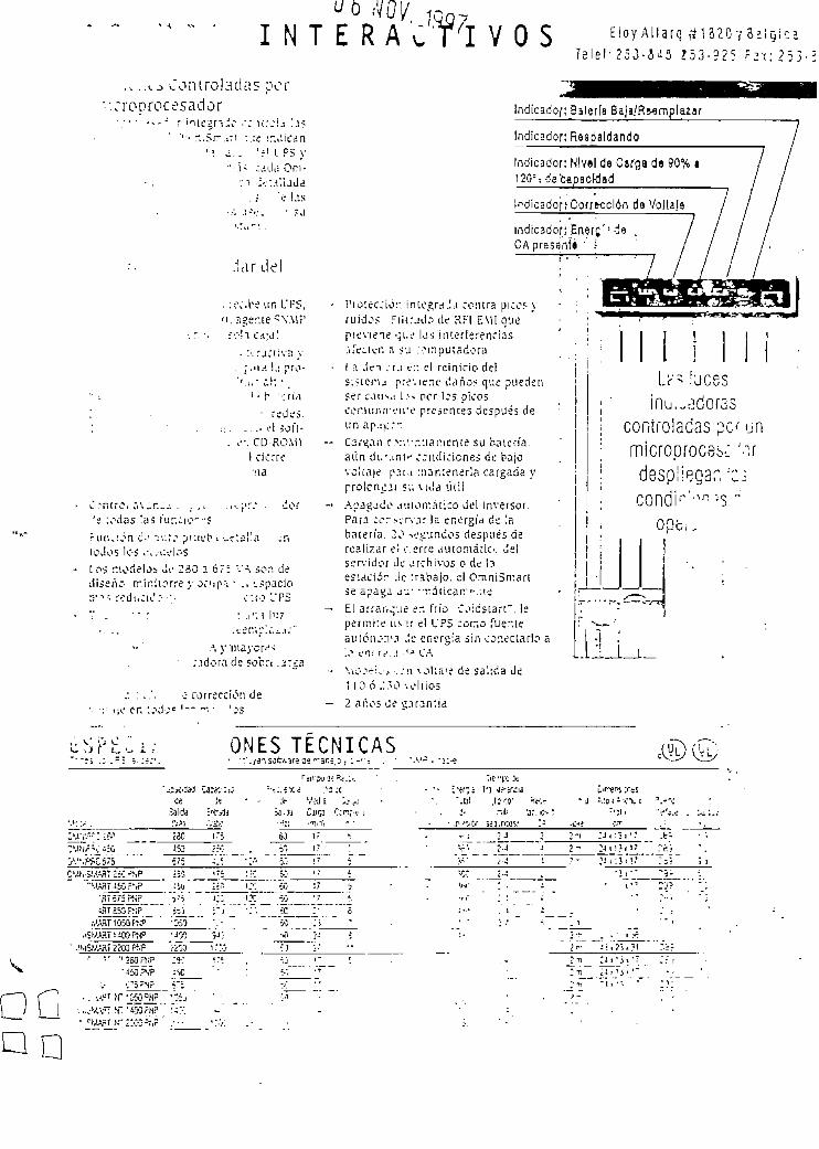
I N T E R A<qn,
¡Ti V O S E I O Y A I I a r < ) í í 1 3 2 Q Y B 2 l Q ¡ c aT e l e ! - 2 5 3 - 9 2 5 ? 2 t : 2 5 3 - 2
., ..^o C o n t r o l a d a s porToorocesaclor indicado/; Satería Saja/Remplazar
Indicador : Respa ldando
indicador: Nlvsl de Carga de 90% i
.lar del
' • h -;ruí
: redes .: ' . . . . . -.'I 50ft-. ,-•. CD-ROM1
1 cierre
L ? n r r o . ;i\^r.-¿ . . .. ,-.:':: .¿or'e :odas !a¿ r"ur.ci-?'--sr i u i . i j n t - 1 "ii:t^ prjL't1 1 uc'.aüa .TIicJos Ic-s .:,.t:ckisLos nocleloi úr 230 ,1 ó": VA. sor. dediseño m i n i í o r r e y ocNp-^ • ., topacio
r.:o VPS
• ;.idora de sobre .:¡:¿a
o corrección de\¡¿ en :.->doe
Pfo:ec;¡ó:: i n i e g r d J a con t r a picos yru idos F i i t r j d o de KF1 EMI quep r e v i e n e -_;i.-,' las i n t e r f e r enc i a s.\re;icr. a su .••."inputadoraI A Jei :r.¡ >;:\i re in ic io dels;?ieru pre ' . iene daños que puedenser cau^,-. 1."- ocr los picosc o m u n i r v i r e presentes después deun ap.it.*".Cardan C-\- .vr.uai: iente su ba te r ía ,aún di.'.mi" crndic icnei de bajovo l t a j e p.ir.i ::ian:ener!a cargada ypro¡cn:^3i ?;¡ v i d a ú t i lApagado jiHoiráiico del inversor.Para ;cr>-.-n-.ir la energía de !aba t e r í a . 2¿ i^'jndos después derea l izar el c.erre automái io . delservidor de archivos o de ¡3esució" Je Traba jo , s! Omni5n:art>e apaga a- ' "ranear*.ueEl a r r a n q u e er. frío Coidsiart" . lepertr.i:e u s i r el l'PS como fuen teautcn-.'-n!3 Je energía ¿in conectarlo a> en; r:'..\ CASu'-o-ri,'.- < . : n \ o l i n ' e de sa'.ida de1 10 ó J.'O -.cilios2 ar.os tí e
IndicadopCofrecclán da Voltaje
Indicador ; E n e r e ' ' - j e .CApresan í i ' ::
:ÜC5S
muñidorascontroladas permícroproceb-: 'despegar, •':.
un
OOó, ,
ONES TÉCNICAS
280
^BT £53 FTiP
//ÁRTlOSQfíJ»
/fflT 2200 PUF
> 250FÍIP
• OQ
GQ

3APLI - APOLLO CURRENT METERS & MODEL APLV - APOLLO VOLTMETEfíS
L
• FOUR MULT1-RANGE UNITS COVER:199.9 uAto 1.999 A. 199.9 mV - (A.C. or D.C.)1.999 V lo 300 V (A.C. or D.C.)
. 3 1/2-DIGIT, 0.56' (14.2 mm) HIGH LEO DISPLAY W/POLAR1TY
* 8UILT-IN SCALING PROVISIONS
. SELECTABLE DECIMAL POINT LOCAT1ON
. AUTO ZEROING CtRCUITS
. FRONT PANEL CALI8RATION ADJUSJMENT
. OVEH-RANGE INDICATION
• NEMA 4/1P65 SEALED FRONT METAL BEZEL
* Accassory Shunts Available For Híghar Curren! Ranges.
OESCRIPTION\ , . , i ¡ i t Vult and Current Meters ore preraium quaiúy instruments designed
, f , . n r h imlusirial applicadons. Wiih mulü-range capabílicy, built-ín provisión, ., .Uní:. Jiid swicch programmable decimal points, these units offer thc,.::i.iu- :n Application flexibÜity. Just four basic models, off-ihe-shelf, from•ni i'i..ii Jistnbutor, cover your voitage and current indicator needs, as welJ as,,i i i- . juirancnls for direct readout from pressure. speed or flow transduccn,
• .in Milicr variable tfiac can be translai^d to voitage or currcnt.\H: ..itriiciive die-cast metal bezel of thc Apollo not ooly enhances the•.n.¡ni:c uf any panel, it can also be seded in the front panel for use in wash-
I ifc.i-. and tough. diny industrial environments. The 3 1/2-digit bi-polari.iv immus sien displayed when currcnt or voitage is ncgative) feaoircs' 114 .2 mm) high, 7-segment LED's for easy rcading. Also feaxurcd are
•% ..hlc lerminal bíocks on the rear that facilítate installation wiring and
SPECIFICATIONSUISIM.AY: 3 1/2-digit, 0.56" (14.2 mm) high, 7-segment LED. (-) miniis sign:^lived when current or voitage is ocgarive. Decimal points ínserted bcfore^•-nd. or 3rd least signiñcam digits by DIP programmíng swítchcs.l'UV.'ER: Available in either 115 VAC or 230 VAC versions. Alíowablc"*or ¡me variation =10^, 50/60 Hz. 6 VA.
IM'L'T RAiNGES; (Selectaile by input and jurnpcr connections.)1 C Voilmetert A.C. Curr*O1 M*t*n O.C. Vortmr»
•'°'<'->>s 0-199.S uA ííntcroa/pps) ti,999 Voto
"> ~<9 V G Í S 0-59.S9c\ tJ9.99Vcít3• ' ' Í V i i l s 0-199.9 mA *]999VoHj
•O /G-IS 0-1.559 arrpa ±300 Voía0-199.9 mV (basic ranga)
\l-'CL'RACY: (23^. 35^ R.H.)• ' Volts- ±{0.1% of Rcading + 1 digit)-' volts - ^0.1% of Reading + 2 digits) (45-500 H.- Current<}-9 MA, 1.999 roA, 19.99 mA: ±(Q, i % of Reading + 1 digit)IJ-9 mA: =(0.15% of Reading -r t digit)'99 A; -(0.5% of Rcaáing + ! digit)
AC Currínt (45-500 Hz)199.9 jiA. 1.999 mA, 19.99 mA: ±{0.1% of Rcading * 2 digits)199.9 mA: ±(0.15% of Reading + 2 digits)1 A: ±(0.5% of Reading + 2 digits)
. OVER-RANGE RATOJGS, PROTECTION, AND CSTDICATTO.V:Oyer-Ran^e ludicatíon on all modcs is tndicated by '-¡¿rjur.g 3 least
signiñcant dígiu.Mai. Volfage on Basic Range Inputs: 75 VAC or DC ,Tcrm. í 10 3 on
volcmetcn. Term. 9 to 3 on curren: meters).Mai. Voltagí oa Termina] Block: 300 VAC or DC (Both .«iiir.eters and
current metcrs).Max. Shunt Currtnts (on currínt meters):199.9 uA thrüugh 19.99 mA: LO x max. range current199.9 mA: 1 amp1,999 amp: 3 ampsCamión; ¡n cirritiis whtrefault cuntntj can cxcced max. j{lo--.¿cie * urrsnc
shawn above, afasT-blowfusc should be insialled ¡n senes •*-itH :~.c - ¿rrenrmeter to przvenl currrnt surges in excess of ¡he ÍTULC. rannss
. TEMPERATURE COEFFICIENTS:
O.C. Currwnt M«Wr»2199.9 \iA (microamoa)3:1.359 mA (miHlampa)
±199. 9 mA«1.999 amw±199.9 mV (bosk: ranga)
D.C.; =100 PPMAC D.C.:.±75 PPM/°CA.C.: =200 PPM/°C A.C.: ±150 PPKV^C
, OTHER SPECTHCATTONS(ForallA-C. ¿c. D.C. current and voltmcterx)'Operatíng Temp«rature Range: 0° to 60°CSíorage Temperature Range: -40° to 30°CRespoose Tune To SUp Change Input: 1 sec. nominalReading Rate: 2 J readings/sec., nominalNormal Mode Rejection: 50 dB 50/60 Hz (D.C. units oniyíCommonModeRejectíon: 110 dB D.C. or 50/60 H z ( D C .Commoo Mode Voitage (comm. to earth): 350 volt pcaicCoostructíon: Metal die-cast froot bczel with blaclc hjgn ¡mouct plástic
case, Front panel metts NEMA 4/CP65 requirements *hcn prop^rlytnstailed (panel gasket and moundng clips íncludcd).
Weigfat: 1.2 Ibs (0.54 Kg).
mly)
DIMENSIONS "In inches (mm)" Note: Recommended mínimummounting clip installation is 2.1"
ciearanca (benind the panel) tor(53.3) Hx 5.5' (140) W. P*HEL CUT-OUT
! ¡53B\•£*
/
i.(«
35•5)
•3.50 (36.5)-
L1"^.i C2.5)
i—
i i
| iL_
1.n uJlM
1
751 *i)
T -o -0-3
(92:^) i.c
77 :?;te-Q ,
(7.5)
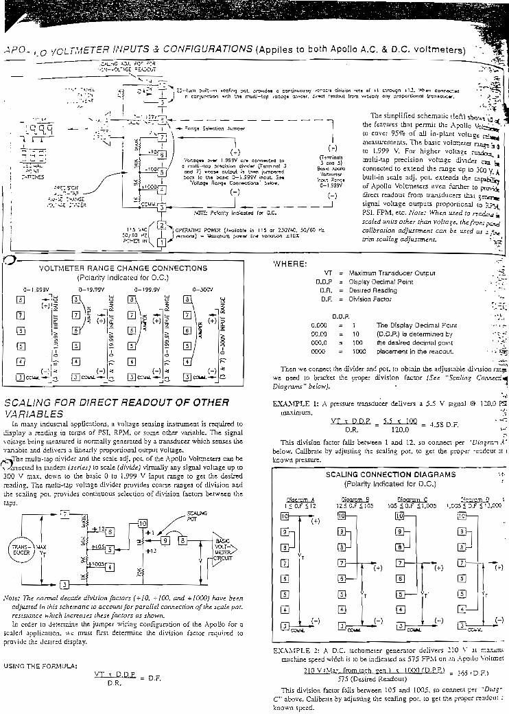
\PQ. , Q ycLTMETER INPUTS & CONFIGURAT1ONS (Applles to both Apollo A.C. & D.C, voltmetenj)
¿5— lurn 5-ji'rt— n icsfírxj ?ot, ;;i-DYid*i a caoiinuo'jsiy gracin csojurxnitxi ^rth Uis muiti— tcp vortcqt firmar. Jirsct
1
Vc4to9«a cv»r 1.999V an ccx^isctM tea rnuiü-lao srícijion drvidw (Termtnol
CTXÍ 7) »fx»« cutoiA >s tn»n jumD«fMtoca la U-.8 'oasx: 3-1.S99V ¡npuL 3«
VcJtaq* Raf>q« Conn^ctíona' ia-kj*.
(TirminolJ3 Sfrt 3}
Bas-c AcwJkjVctmeter
Irjxa Sarxja0-1.S95V
NOTIj Patarrty inakatirt tor D.C.
OPEPATlHG PO*ER (Avcilob!» in 115 or 2XXK. :O/60±10X
Lirwjgn fU. 'Mían cofln*ctany arnportional troniaoc«r.
•Sv*The simpiified schematic ilefO showV^j
the featurcs that pcrmit the Apa U o Vt ' "to cover 95% of ail in-plant voitanetneasuremcnts. The basic voltmctcrto 1.999 V. For higher voltage r^multi-tap precisión voltagc dividerconnectcd to extcnd the rangc up to 3Co V ibiult-in scale adj. poL exienda theof Apollo Voltzneters evcn funher todircct readout troco transducers ihax c—-,,signal voltage ourputs proportÍDnal to ?jPSI. FPM, etc. Note: iVTien ¡ued ¡a n:cdcv kscaled units o ¡he r than voltaje, thc. frons x^calibrarían adjusrmcnt can be íised as ¿ trim scaling adjustTncni, • ^3
•- »
L
a-VOLTMETER RANGE CHANCE CONNECT10NS
(Pclariíy Indicated íor O.C.)
Q-1.999V 0-199.SV 0-3CCV
«
sE 0
SCALING FOR D1RECT READOUT OF OTHERVARIABLES
tn many industrial applications, a voltage sensing insmimcnt is requircd todisplay a readüig io terrns of PSI, RPM, or some other variable. The signalvoitags being measurcd is nonnally gencrnted by a tnnsduccr which scnscs thevariable and delivers a Unearly proporcional ourput voltage.i¿WTne mulü-tap divider and the scale adj. poc. of the Apollo Voltmeten can be-v ^íinecisd in umdem issri¿s) to scale (divide) virtually any signa! voltage up to3CO V rnax. dowti ;o the basic O to 1.999 V input range to get the destredreadins. Tne multi-up voltage divider provides coarse rangea of división andihe scaüng pot. provides continuous selecúoo of división factors between the
iVofe: The normal decade división factors (+10. -100, and +2000) hnve beencdjítsied in this schematic to account forparalld connecríon ofihe scale pot.resístanos wnic/i inervases th¿S£ faciors as shown,In crder to determine the jumper 'Airmg confíguradon of the Apollo for a
scaled application. we tnust flrsi determine the división factor requircd toprovide the desired dispíay.
U5INGTHE FORMULA:
VT x D.D.P,D.R.
= D.F.
WHEHE:VT = Máximum Transducer Output
O.D.P = DIsplay Decimal PointD.R. = Desired ReadingD.F. = DMsíon Factor
O.D.P.
O.COO = 1
CO.CO = 10
CCO.O = 100
COCO
The Díspiay Decimal Pcint(D.D.P.) ís datermineo bythe desíred decimal pcrnt
= 1000 ptacament in the reaaout
Then '-ve cormect the divider and pot. to obtain the adjustable divisiónwe aeed to brackct the proper divisioa factor (See "Scalin^ Cons-ccr.
" below). *
= 4.53 D.F.
4É'1
EXAAffLE 1: A pressure transducer deÜvers a 5-5 V signal & 120.0 P3máximum. **-'
VT x D.D.R = 5.5 x 100D.R. 120.0
This división factor falls between 1 and 12, so connect per 'Dia%rc.-i Á'below. Calíbrate by adjusdne íhe scaling pot. to get the procer -sadcut 21 iknown pressun:.
SCAUNG CONNECT1ON DIAGRAMS v t - |(Polarity Indicated for D.C.) '
1 < O . F < 1 2 12<O.F<105 105 <O.F < 1,005 t.CG5 < 3.F < 'J.íXX
'
LL!
B@Elf 1 1
— •*- iu^ — i(+) ^^
T Rl.l / l
E—
liuj
Uh
CIH^ m
Sm
{-) pri
(+)
(HT H —
L^J
En
— -,
1
H' <~> m
(*) ^m
T- ü!
E—1
-
"1 '
•
1 <-> rn
(•¡•)
T
(-)
'- COUU. "" ' — 'CCIAL ' 'CC4*L ^^ CCI.V.
EXAMPLE 2: A D.C. tachometer generator delivers 210 V at rr.a.ximumachine speed which is to be indicated as 575 FPM on on Ac-oilo Vo¡un¿!
?mVíMa.-, fromtach. gen.) •: IQOOfP.PP.) = 7 6 5 , D F )
575 (Desircd Readout)
Thís división factor falls between 105 and 1005, so connect per "Diug".C" above. Caiibratc by adjusüng the scMLng pot. to get the proper readout ATcnown speed.

INPUTS á CONFIGUFtATJONS (Appiies to both Apollo A.C. ¿V D.C. current meters)
•-- — 7 ~•^••:«• -,iji.-i
\~
/ •-v«-"• -.'' - ,'.-x;--
r n Q -^r-3)u ~"l l ^ =C-."" '
iVi.:~ ^;>' x""
ss(— SÍ.H X._, ~-_-l?
si.-* :W*CE,-: - t :vceR
ÍO
V .y
V~
^•"-3^
í|
5! 3-1 999UA
lí1 0-'9.59 UA,
" 4ttl 0-1 3MA
=1
4'I CCMU
112 V1C[50/W HZ;e«a wl
' y
i n ^yii-jx^Jon wrtn í."-« T>.rtJ— Ico -<t><tiX}« OrtxJ^r, 2.r»ct rwxvxít írwn vrruoiÍY orrr prcwtxyxii lr^n»o\xa«',
:^jx
) * 1 r~^•^ m 5 > q '^- Apollo Current Meters incorpórate a basic— ,' "*" r_fr»ra rrtn M*rxa muma. | Q to 199.9 mV voltmeter Circuit togcthcr -AiLh^ \ a stnng of buüt-in current shunts that can be-=-¡ <? • t \ connected lo provide current "neasunng"-T ¿^^000 4wn ¿^d'rn'^ti ranges from 0 to 199.9 ^iA to 1 .999 imps m"gi^ «^^Ta* ^ a Q-lM-9fIlV 5 decade stcps. A buik-in scaling pot. also
1 s*o«rfljoq oo ;.jnx>«- írom a io 9 ailows the unit to be used as a scaisable5j " r*a. ^^ -^^Ttó"^ raülivottmeter and provides for arbitrar/\ Twm^oa J ond 9. cuiTcnt scaHng. Note: When used to reudout
"Tj (~) ín scaled units other than voltaje or curr?~tt.' ¡jTs i the froni panel calibrarían adjustment can bt
' 3 i^ .,_ _ , * ( J irLJt ,UA^.-"" ajea or a n/ic fnm scaiins adjustment.T^ HOic re^ofrtY ifx>cut*o for D.C, -1 3 's>~i" j OP^F-ATWG ?Üi»Cí (Am¿at>l« Vi 115 or UCVtC M/40 Hl^ c^) - U,™ PO^ ,„ «^^ V- 1CX
CUBREN! METER SCALING
Thc numerical current valúe disptayedby tbe Apollo current meter can be scaleddown to aimost any lower numérica! valuéby connecting the scale adj. poL Thís potcan be sel to divide the normal numérica!current reading by any división factorbetween -rl and -r!3. ía addiüoru íhe shuntresistancc chosen can be reduced byconnecting the currtnt lead to a lowerresistance (highcr ran$e tap).
EXAMPLEla the diagram (left), thc Apollo Current Meter has becn connsrcted to
rneasure a círcuit currcnt to 120.0 mA máximum. However. ín this appücanon.the readout is 10 be in pcrccnt of load currcnt. with 120.0 mA bem? equivalentto 100.0% readout The scale adj. pot. connected as sho^n can be adjilsted toreduce thc normal 120.0 mA display to the tOO.0% display disirrd. The tnputcurrcnt leads could also be connected to 4 and 3 instcad or" 5 and 3 as shown,aad this would yield a readout to 100% and allow the decimal pomi and léaseiigniñcant digit (0.1%) to be dropped.
Scaling to obtain a numérica! readout higher than the numérica! valué of thecurrent can also be done Ín most cases by simply feeding the currtnt ínput intoa lower range. However. at the higher current range (1.999 A) and wiih sxieoialshunts, carc should be takcn to avoid e.xcceding máximum shunt currcnt.
For example, íf the unit is measuring a máximum currcnt of 1.3 amps(current Jlowin^ between ¡erminnls 3 and 4), íhe numérica! currcnt valué 'A til be1.300 displayed. Here. it is impossible to íncrtasc the numérica! scaled valué tosay 1.500 by connecdng to the nexi sensidvity (199.9 mA) since the 1.3 ampactual currtnt exceeds thc máximum current raring of this range >S¿e"Specificanons " for máximum curren*.)
CONNECTJONS'••• J^pictsd in the cirawing of the Apollo Unit. ali connections are made to a
"*••'*:o!fi tsrmiaal blcck for case of insudlation. To rtmove the block. pulí" 'w bacSí of thc block uncu ít sudes clear of the terminal block shroud.
li'Jüiin: r¿rrninal block should NO'L be removed with power applíed to the
POV/ER CONNECT10NS^nrnary AC c-owcr is connected to Termináis 1 and 2 (Marked A. C. Power,
-• .vt/ un the Uft-hand side of the terminal block). For best resulLs, the AC•' HT >hould be rtlatively "CUan" and v/ithin the specified ±¡10% variadon
•;" Drawing power from heavily loaded circuits or from circuits ihat also•' '•cr loads that cyclc on and off. should be avoided.
:I)PUTCONNECTIONS"rui cor.necuons and ranee cooñguraüon jumpers are made on Termináis 31JSn 10 or 11. (For detailed information. see "Inpuis and Applicaríons".)"^n ccnnecüng and instailíng the input wires, the following guide unes
"J|d be obsen-cd. (This is ¿specially truc, in electrically "noisy"
5igna] ¡nput knds in the same conduit or race ways withfeeding motors. solenoids. SCR controls. heacers, etc. tdeally.
re's should be run by themseives in a sepárate conduit.l¿ads wíthin electncal enclosures should be routed as far from
, rnotor staners. control relays, transformers, and other similarmpor.ents as cossible.
C. vVhen shielded wire is used. connect the shield to the signal commontermina! of the Apollo Volt or Currtnt meter and leave thc other cnd of *he-hield uncoanected and insulated from machine ground.
DECIMAL POINT SELECT1ONrhe Apollo Volt and Current meten nave DIP switches located on üie side of
'he umt for the selecúon of 1 of 3 decimal points for dispiay.

u,, j inis ¿re designed to be pancl-mounted with a gasket to providc' ' t , i -caí. Two mounting clips and screws are provided for easy
'"' ,',, i .QiiJcraüon ihouíd be given to the thickness of the panel. A' '" ' i u t > -^ Ic¡° t*"n ^y dislort and not provide a water-üghc seah
' " ' .itfiíirJ mttitmufn panel thickness ¡s 1/3".)' ' M i l ,|K- ¡Mr.el CJt-out has been cornpleted and dsburred. carefully apply! Y-ACI ü' ibe pane?. DO NOT APPLY THE AD HESITE SIDE OF THE
"\> KK T TO THE BEZEL. Insen ihe unn inio the panel.\-, tkpicicd m the drawing. :nsíatl -he screws into the narrow end of the
...miifii; ^lips. Thread ihe scre-.vs mto the clips un ti! the pointed end justprotrudes through the other síde.
ínstall each of [he mountingclips by inserring the wide lip of theclips into the wide end of the ho!e,íocated on either side of the case.Then snap the clip onto the case.
Tighten the screws eveniy lo
7HICK
,CUT-¿WAY^ '-lEW CF
^\EJ
MCUMTTIG -CLP
apply uniform compressíon, thusproviding a water-tight seai.Cau£ian:Only mínimum pressurc isrequired lo seal panel. Do ¿JOToverñghten scrws.
-GASKcT - 0.100" ..-:>=••
%¡
SCAU.'ÍG'ADJUSTWENT
--poaoStüEL
<. « s 3 J.33 ¿y5-2S
MOUNT1HC CUP'2 PLACES
WOUNT1NG SCRETíV-2 PLACES
'^
TEMPERATURE MONITORING IN A B1SCUIT BAK1NG OPERA!
1 2 Í Í 5 G 7 3 3 I O
Uat
división factor is rcquircd. Use die equatíoa díscussed in íhc ÍC.XLDivisión = fMasimum OutpuÜ * D.P.P. = f i O í x !
Factor (Desired Display) (6C*J = 15.7 (D.F.)
l_u
/SHfEH)
/f \H[ | CCMU.
\ /i
rv*u
V-.cn,moa of
r^ii J) and-. -.r.ectcdrfmuial 3).
r-,s to a ponabí; ,by i
7HERUOUETIH
A bíscuii baker has temperarme controllers on his avena that have a dial forsening the tempcrature of his ovens. He would tuce to have a digital dispiay of
tempcrature for case of motütoring. He has determined, by talking to theperarure controller manufacoirer, thcrc ía a O to 10 VDC voltage avaiíable
from the controller, that represents a temperatura of approximateíy O to 600°F.An Apollo DC voltage indicator is ídeally suítcd to tbis application. It is
apparent that a standard range wjll not sadsfy this rcquirement; therefore, fieidscaling is required. The first thing that must be done is to determine what
ít can be seen that the división factor fails benvesn !2 ..id ¡05 (5"Sea'. ? Conntcñon Diagrams"). This is accomplished -•/ .rr.necdag
jtiinp.,-. ->erween %10" (Terminal 6) and Terminal ÍO :h.einpur), and a jumper berween Terminal 9 and Tenrunal -iconductor shielded VÁTC to rainimíze noísc pickup, 'hetemperamre controller output is. cormected to "COMM. " ' Tt"HIGH" Síde of the output of the temperatura controller"V^" {Terminal 7). The shield ts also connected to "CD.V/.W
The Apollo is now ready to be calibrated. The baker has i,digital thennometer. So in this case, calibración wül becausing the Apollo indicator to agrce wida üie portable J¡cThe baker sets bis oven to bis normal baking tempcraturc otthe temperature probé in the oven and waits for it to reach -•the oven has stahilized. ai its operadng temperature, the raicr •.-r.oiy adjusathe "coarse" scaíing adjustmeot, íocated at the rear -u" T.C •:•.. mol ¡bedisplay ¡s cióse ¡n valué to thai indicated on the digital ihcrnu-mcirr. He ibea )removes the "fine" scaíing access plug and adjusts üv: ''~i¿ ' scaíing }adjustment until the dispíay agrecs with íhc digital thermomcier He rcpiaca ¡the access plug to keep dust out of the Apollo. The Apoúo •• iimctsr DO«indicates the oven temperature and the faaker can monitor ~.iiprecise ly.
h" He instillí i
VOLUME iNDICATIONA raanufacturer who uses vais of chemicals ín his process has been using
the output of load cells. connected to a circuh thai m turn drives a I rnA DCanalog meter movement to display how full the vat is. The meter dial iscalibrated O to 1500 gallóos.
An Apollo DC current indicator ís ideally suíted to this appücaüon. U tsapparent that a standard range wül not sarisfy this requiremcnt and freídscaíing is required.
[tcan be seen that the I mA for 1500 galions can notbc accomplished usingLhe 1.999 mA ranee; howevcr, the máximum input of ImA docs not exceedthe máximum input OD the 199.9 uA range, so this range is selected. This isaccomplished by connecting the jumpers as described in die "Scaíing" section¡e.g. from "199.9 pA" (Terminal 8) to Terminal ¡I and a jumper berweenTerminal 10 and (he "199.9 mV" basic input (Terminal 9}¡, Then, the Apollois connected in the circuit to replace the analog meter by connecung the"199.9 ¡iA" (Terminal S) where the 'V terminal of the analog meter wasconnected, and connecung the "CO.V/Af." (Terminal 3) where the "-" terminalof the analog meter was connected.
The Apollo is now ready to be caiibrated. The operator filis the vat until itis completely full and he knows he has 1500 galions. He then adjusts the
coarse scaíing adjustrnent on the rear of the Apollo indicaior -jr/^l 'he dispbyreads approximatcly 1500. He thcn removes the "fine ' ^aíir.ií üJjustmcntaccess plug and adjusts the "fine" scaíing adjustmeoí unul L*IC Jisplay rradaexactly 1500. He rcplaces the access plug to keep dust and -¿atcr out of tbcApollo. The Apollo current meter now indícales me exant r;ur-r<r of galleasin the vat. No decimal point is sclected bccause the resoluüon ií 1 gallón.

VOLTAGE & CURRENT MEASUREMENT APPLICATIONS (Cont'd)
i CURRENT MONITOR1NG OF A DC MOTOR t~
|t ,
¡j-ircd 10 monJtor ihe power supply volLige and load currcnt of a 120, > i -.nuiur. The máximum load current is 100 amps.
•i.c \poilo DC Voluneter, Model APLVD, is coañgured for ihe 199.9 V•-I..IL-I! ranee by connecdng the " -100" (Terminal 5) to thc 1.999 V basíc..^TTiinál S). The "CONGví." (Terminal 31 is connectcd to the negadvc
••L !?rol' ihe power suppiv and the " V^" Input (Terminal 7) ÍS connected»c rni'.iuve terminal of thc power supply. The resoluüon of thc display is\s "D.P.I" is selected.
The Apollo DC Current Meter, Model APLJD, ¡s conügured by simpiycoanccüng the "CONÍM." (Terminal 3) and the "199.9 mV~ baste mput(Terminal 9) to thesense termináis of the e-xtemal 100 amp cunrnt shunt (.AJ3-SCM-100). The cxíernal shunt is then conncctcd ín series wilh thc ncgauvcterminal of the power supply. Thc rcsolutioa of the dispiay is 0.1 Jzcp,thcrcfore "D.P.l" is sclected.
Thc Apollo volt and curren! meters wiÜ now indícate the power supplyvoltaje and load currcni of thc DC motor prcciscly.
t Note: Forhigh AC currents, ¡t ¡s recommendad that (ha Model APUT be used with a cvrrení íranr/ormsr.
ORDERING INFORMATION
MOOELNO."APLVD--APLVA•-APL1D-•APLIA
-,
oescñipnoNAoollo OC VoltmeterAooilo AC VoltmeterApollo DC Current Meter
PAPTTHUMeERS230 VAC
APLVD410APLVA410APUD410
Aoollo AC Current Meter 1 APIIA-MO-10 amo Current Shunt-100 amo Current Shunt
115 VACAPLVD400APLVA¿00APUD4OOAPLIAAOO
APSCM010APSCM100
For more intormation on Pricing, Endosurea, 4 Panel Mount Kits, rafer to the RLC Catalog orcontact your local RLC distributor.
* Volíage drop aijvUcurrcnJ - ¡00.0 mV máximum. Conrwiauj curre/u shouldrux cxcecd ¡¡5% ofranng.
** Unía are shipped calibraled ¡o the follawing readingí:
I4QDEL NO. DlSPl T Q IHPUTAPLVD 1999 *? 1 999 VOCAPLVA 1999 3 1 999 VACAPLID 1999 9 1399mVOCAPLIA 1399 3 i99.9mVAC
D33

.m-
Overvoitaae arresters -cr '.r-e ~-=as'.
Overvoltage protection for the measuring Une
Overvoltage protecíion type B 62 - 36 G
Standard rve^/oltage protection tn two-wire lechnology for the measunng !inebetween sensors and signal ccnditioning instruments as v/ell as for Q/¿ ... 20 mA-circuitsoí compací sensors and indications also suitable for ia-arcuits(also íor ZZFQ C-circuits — avervoilace protecüon requires no ov/n apprcvaí)C^aractenst'cs vaiue; 12 .. 35 V DC, max. 1 AProtection: IP 20 (m housing IP 65)
Price in DMOvervoltage protection type B 62 - 36 G
Add, price in DMHous ingX without housingG K Plástic housing IP 65G A Alumínium housing IP 65
193,-
0.33,'
146.'
Ü S B 3 6 G Order nurnber for overvollage protection type B 62 - 36 G
Overvoltage protection type B 53 -19
Overvoliage protecíion for the measuring Une between conductive elecírodes and the appropriate signal conaitioralso suitable for ia-circuitsCharacteristics valué: max. 19 V ACProteciion: IP 20 (in housing IP 65)
Price in DMOvervoltage protection type B 53 - 19
Add. price in DM
HousingX vmhout housingG K Plástic housing IP 65G A Aluminium housing !P 65
136,-
0,-38,-
146,-
U S B 5 3 1 9 Order number íor cvervoKage protection type B 53 - 19

Overvoltage protection for the supply Une
Overvoltage protection type B 51 - 75
Overvoltage proíection type B 61 - 300
S^cc'y 5nd ccrtrol une proíection for allPr:;ec;;on: !P 20 (¡n housing IP 55)
. S^cc'y 5nd ccrtrol une proíection for all instruments v/ith 110 ... 300 V AC.DC. max. 16 A
Overvoltage protection type B 61 - 300 Fl
Supoly 3nd cc-ntrol :me protection with leakage currení circuit íor all Instruments wíth 110 ... 300 V AC/DC. max. 16 AP'Diection: IP 20 ('.n nousing IP 65)
Overvoltage protection type 8 62 - 36 G
Suppiy and control líne protecíion for all instruments wiíh 12 ... 36 V DC. max. 1 AProtecuon: IP 20 (¡n housing IP 65)
|, . _ _
R j Basic pnce in DM 193,-.Í Add. price in DM
j Type] 6 1 - 7 5 16 . . . 53VAC, 16 ... 75 V DC o.-! 6 1 - 3 0 0 110 . . . 300 V AC/DC 0,-j 6 1 - 3 O O F I 110 ... 300 V AC/DC wiíh leakage currsnt Circuit 0,-¡ 6 2 - 3 5 G 12 ... 36 V OC 0,-: Approvals; . X vvithout of-- Housing! X wiíhout housing 0.-¡ G K Plástic housing IP 65 with carrier rail 38.-
G A Alurhinium housing IP 65 wíth carrier rail and earth terminal 146,-
U 3 B . X , Order number íor overvoltage protection type B 61 or type 62 - 36 G
i AP-301
A

Overvoltage protection
Carner raí! 323cc 'o EN 50 035
Carner raí! 35 x 7.5acc. to EN 50 022
54
i TT
T .GL59
n
25
Plástic housing for overvoltage protection
o4.5
J,
Pgl6 ;50
160
for max. 2 avervoltage arres. . 3. with VEGASON Ex, VEGAPULS Exinclusive carner rail and breatner íacility
l*
pih-
i-f;v*
Aluminium housing for overvoltage protection
130*1 05,5
Pg 13.5
for max. 2 overvollage arresters e.g. with VEGASON ex. VEGAPULS Exinclusive carner rail and brealher facility
302-AP

Anexo
F.- Certificado
i

SIEMENS
Gerencia GeneralSeñoresEscuela Politécnica Nacional
Facultad de ingeniería Eléctrica
Ciudad.-
Teléfono 507 134Fax
NombreDepartamento
TeléfonoFaxe - mail
Su ReferenciaNuestra Ref.:Ciudad, Fecha
Luís PalauGER.GEN
(02) 474060(02) [email protected]
Tesis de GradoQuito, 24/09/01
Asunto: Tesis de Grado basada en Proyecto Compuerta de Ishpe
Estimados Señores;
Por medio de la presente y en mi calidad de Gerente General de Siemens S.A., dejo constancia queautorizamos al Sr. Ramiro Eduardo Cordón Salgado a utilizar información técnica del proyecto de lareferencia y de los productos Siemens en la elaboración de su Tests de Grado.
Así mismo certificamos que el dicho Señor, realizó el diseño, la instalación y puesta en marcha delsistema a que se refiere el tema de su trabajo.
Cordialmente,
Luis PalauGerente General
Siemens S.A.
Sede principal: Quilo. Calle Manuel Zambrano y Panamericana fJone Km. 2'/i • PBX 474060 - Fax; 407733 - CasiKa postal: i7-0-<*i07M
Sucursal: Guayaquil. Av. Miguel H. AlcívarMz. 5O6. Edificio Torres OeJ Norte, Oíc. B707 • P8X; 637*01 • Fax: SB74Q4


![CALIFATO Y RELIGIÓN. LAS SORPRENDENTE …aleph.academica.mx/jspui/bitstream/56789/30607/1/42-134-2007-0647.… · Arab culture, while al-Ma'mun, ... [Consultad 3 dea marzo el 2006],](https://static.fdocuments.ec/doc/165x107/5b949f3909d3f2bd1e8db37a/califato-y-religion-las-sorprendente-aleph-arab-culture-while-al-mamun.jpg)


