EL SERIES - beyma.de · como en activo (bi-amplificado) con todos ellos 2.CONEXIONES...
32
EL SERIES EL-10 EL-12 EL-15 EL-30 EL-18BR Pol.Ind.Norte-Perpinyà,25 08226 TERRASSA (Barcelona-SPAIN) [email protected] www.master-audio.com Dic2008 / Dec2008
Transcript of EL SERIES - beyma.de · como en activo (bi-amplificado) con todos ellos 2.CONEXIONES...

EL SERIES EL-10 EL-12 EL-15 EL-30 EL-18BR
Pol.Ind.Norte-Perpinyà,25
08226 TERRASSA (Barcelona-SPAIN) [email protected]
www.master-audio.com
Dic2008 / Dec2008
Amate Electroacústica,s.l
EL Series. Version 1.3 Dec 08
2
ESPAÑOL
1.INTRODUCCIÓN 1.1.Generalidades Amate Electroacústica, s.l. le agradece la confianza depositada en nuestros productos de la nueva Serie EL. Le sugerimos lea atentamente las indicaciones que a continuación exponemos, confiando en que le serán de gran utilidad para obtener sus mejores resultados. 1.2.Características y presentación EL-10
- Sistema de 2 vías Full Range - Altavoz de 10" de alto rendimiento - Motor de agudos con diafragma de Titanio de 1" ½ - Difusor de dispersión asimétrica 50º a 100º(H) x 55º(V) - Filtro divisor pasivo diseñado con precisión para obtener los mejores resultados - Capacidad de Potencia de 150 W r.m.s
- Sensibilidad de 96 dB (1W/1m) EL-12
- Sistema de 2 vías Full Range - Altavoz de 12" de alto rendimiento - Motor de agudos con diafragma de Titanio de 1" ½ - Difusor de dispersión asimétrica 50º a 100º(H) x 55º(V) - Filtro divisor pasivo diseñado con precisión para obtener los mejores resultados
- Capacidad de Potencia de 200 W r.m.s - Sensibilidad de 98 dB (1W/1m)
EL-15 - Sistema de 2 vías Full Range - Altavoz de 15" de alto rendimiento - Motor de agudos con diafragma de Titanio de 1" ½ - Difusor de dispersión asimétrica 50º a 100º(H) x 55º(V) - Filtro divisor pasivo diseñado con precisión para obtener los mejores resultados - Capacidad de Potencia de 250 W r.m.s - Sensibilidad de 99 dB (1W/1m)
EL-30 - Sistema de 2 vías Full Range - Dos altavoces de 15" de alto rendimiento - Motor de agudos con diafragma de Titanio de 1" 3/4 - Difusor elipsoidal de directividad constante de 90º (H) x 50º (V)
Amate Electroacústica,s.l
EL Series. Version 1.3 Dec 08
3
- Filtro divisor pasivo diseñado con precisión para obtener los mejores resultados - Capacidad de Potencia de 600 W r.m.s - Sensibilidad de 100 dB (1W/1m) EL-18BR - Refuerzo de bajas frecuencias - Altavoz de 18" de alto rendimiento
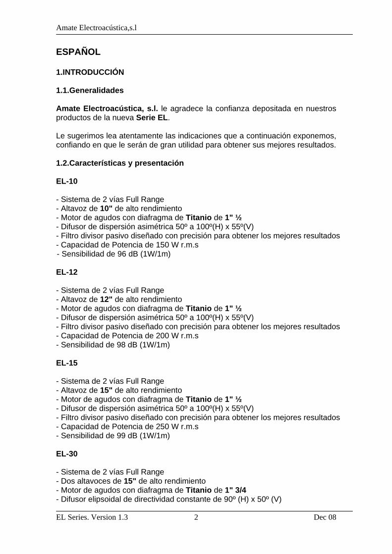
- Capacidad de Potencia de 400 W r.m.s - Sensibilidad de 100 dB (1W/1m) - Fácil utilización en pasivo-paralelo con los recintos EL-10, EL-12 y EL-15 así como en activo (bi-amplificado) con todos ellos 2.CONEXIONES 2.1.Descripción conexionado 1 1 Fig.1. Conexiones para EL-10 / EL-12 / EL-15
1 1
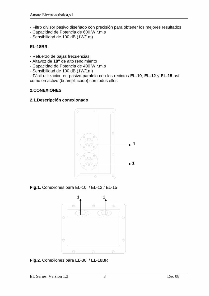
Fig.2. Conexiones para EL-30 / EL-18BR

Amate Electroacústica,s.l
EL Series. Version 1.3 Dec 08
4
1-SPEAKON: Todos los modelos incorporan dos terminales Speakon y están preparados para su perfecta conexión en un sistema en paralelo. ATENCIÓN: Utilice en lo posible cable-manguera de dos conductores, sin apantallar, bicolor y de buena calidad. Se recomienda el uso de una sección de 4mm2 como mínimo para cada conductor. Evítese largas distancias de cableado ya que provocan importantes pérdidas de potencia y calidad. 2.2.Configuraciones 2.2.1.Configuración Full Range Stereo Conectar cada salida del amplificador LEFT/RIGHT a cada unidad, mediante dos mangueras, independientemente. Fig.3. Configuración Full range stereo 2.2.2.Configuración Full Range en Paralelo Conectar una primera caja desde la salida del amplificador a su entrada de Speakon, respetando siempre la polaridad positivo +1, negativo -1. A continuación, realizar un puente mediante manguera, desde esta primera caja a la segunda. Con esta configuración podrá conectar, por ejemplo, cuatro cajas a un mismo amplificador. Fig.4. Configuración Full range en paralelo
Amate Electroacústica,s.l
EL Series. Version 1.3 Dec 08
5
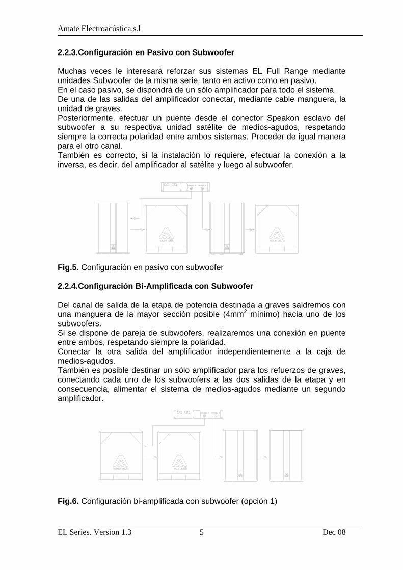
2.2.3.Configuración en Pasivo con Subwoofer Muchas veces le interesará reforzar sus sistemas EL Full Range mediante unidades Subwoofer de la misma serie, tanto en activo como en pasivo. En el caso pasivo, se dispondrá de un sólo amplificador para todo el sistema. De una de las salidas del amplificador conectar, mediante cable manguera, la unidad de graves. Posteriormente, efectuar un puente desde el conector Speakon esclavo del subwoofer a su respectiva unidad satélite de medios-agudos, respetando siempre la correcta polaridad entre ambos sistemas. Proceder de igual manera para el otro canal. También es correcto, si la instalación lo requiere, efectuar la conexión a la inversa, es decir, del amplificador al satélite y luego al subwoofer. Fig.5. Configuración en pasivo con subwoofer 2.2.4.Configuración Bi-Amplificada con Subwoofer Del canal de salida de la etapa de potencia destinada a graves saldremos con una manguera de la mayor sección posible (4mm2 mínimo) hacia uno de los subwoofers. Si se dispone de pareja de subwoofers, realizaremos una conexión en puente entre ambos, respetando siempre la polaridad. Conectar la otra salida del amplificador independientemente a la caja de medios-agudos. También es posible destinar un sólo amplificador para los refuerzos de graves, conectando cada uno de los subwoofers a las dos salidas de la etapa y en consecuencia, alimentar el sistema de medios-agudos mediante un segundo amplificador. Fig.6. Configuración bi-amplificada con subwoofer (opción 1)
Amate Electroacústica,s.l
EL Series. Version 1.3 Dec 08
6
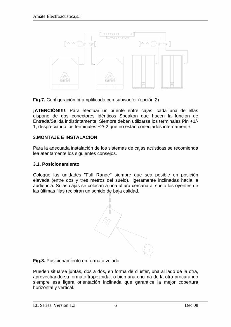
Fig.7. Configuración bi-amplificada con subwoofer (opción 2) ¡ATENCIÓN!!!!: Para efectuar un puente entre cajas, cada una de ellas dispone de dos conectores idénticos Speakon que hacen la función de Entrada/Salida indistintamente. Siempre deben utilizarse los terminales Pin +1/-1, despreciando los terminales +2/-2 que no están conectados internamente. 3.MONTAJE E INSTALACIÓN Para la adecuada instalación de los sistemas de cajas acústicas se recomienda lea atentamente los siguientes consejos. 3.1. Posicionamiento Coloque las unidades "Full Range" siempre que sea posible en posición elevada (entre dos y tres metros del suelo), ligeramente inclinadas hacia la audiencia. Si las cajas se colocan a una altura cercana al suelo los oyentes de las últimas filas recibirán un sonido de baja calidad. Fig.8. Posicionamiento en formato volado Pueden situarse juntas, dos a dos, en forma de clúster, una al lado de la otra, aprovechando su formato trapezoidal, o bien una encima de la otra procurando siempre esa ligera orientación inclinada que garantice la mejor cobertura horizontal y vertical.
Amate Electroacústica,s.l
EL Series. Version 1.3 Dec 08
7
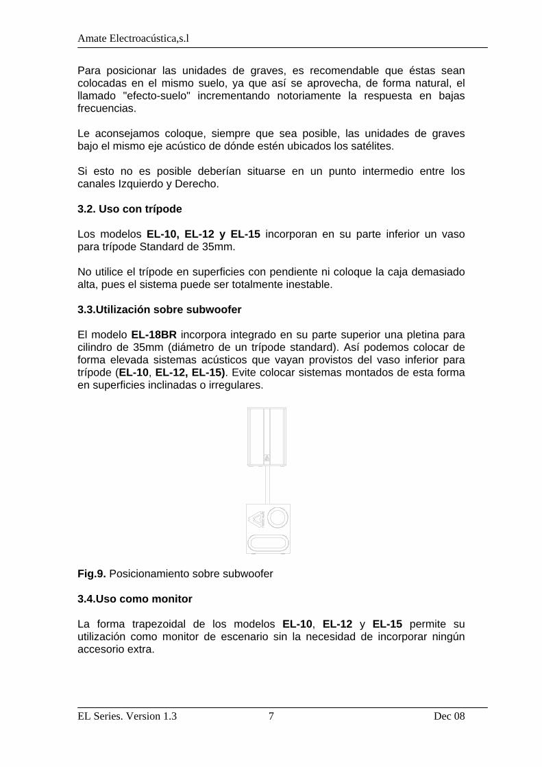
Para posicionar las unidades de graves, es recomendable que éstas sean colocadas en el mismo suelo, ya que así se aprovecha, de forma natural, el llamado "efecto-suelo" incrementando notoriamente la respuesta en bajas frecuencias. Le aconsejamos coloque, siempre que sea posible, las unidades de graves bajo el mismo eje acústico de dónde estén ubicados los satélites. Si esto no es posible deberían situarse en un punto intermedio entre los canales Izquierdo y Derecho. 3.2. Uso con trípode Los modelos EL-10, EL-12 y EL-15 incorporan en su parte inferior un vaso para trípode Standard de 35mm. No utilice el trípode en superficies con pendiente ni coloque la caja demasiado alta, pues el sistema puede ser totalmente inestable. 3.3.Utilización sobre subwoofer El modelo EL-18BR incorpora integrado en su parte superior una pletina para cilindro de 35mm (diámetro de un trípode standard). Así podemos colocar de forma elevada sistemas acústicos que vayan provistos del vaso inferior para trípode (EL-10, EL-12, EL-15). Evite colocar sistemas montados de esta forma en superficies inclinadas o irregulares. Fig.9. Posicionamiento sobre subwoofer 3.4.Uso como monitor La forma trapezoidal de los modelos EL-10, EL-12 y EL-15 permite su utilización como monitor de escenario sin la necesidad de incorporar ningún accesorio extra.

Amate Electroacústica,s.l
EL Series. Version 1.3 Dec 08
8
Fig.10. Posicionamiento en formato monitor 3.5.Uso en aplicaciones de Directo (móvil) Para una aplicación móvil, para Directo o Discoteca, la ubicación clásica sería la de situar las unidades de graves (una ó dos por canal) a cada lado del escenario (sobre éste). Fig.11. Aplicaciones de directo Para conseguir una reproducción libre de obstáculos, se recomienda coloque las unidades de Medios-Agudos por encima de las unidades de graves a unos dos metros de altura. Si no se dispone de esta altura es conveniente utilizar el clásico trípode para cada caja y dejar las cajas de graves en el suelo. ¡ATENCIÓN!!! En recintos con problemas de acústica y en los que es necesario reforzar la respuesta en bajas frecuencias es recomendable agrupar todos los subwoofers en un mismo punto. De esta manera evitaremos cancelaciones y obtendremos un nivel de presión acústica mucho más elevado. 3.6.Difusores asimétricos y giratorios Los Modelos EL-10, EL-12 y EL-15 incorporan difusor de dispersión asimétrica que permite optimizar la cobertura tanto en posición horizontal como en vertical.
41º
Amate Electroacústica,s.l
EL Series. Version 1.3 Dec 08
9
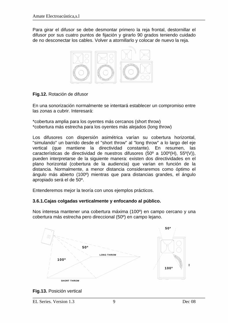
Para girar el difusor se debe desmontar primero la reja frontal, destornillar el difusor por sus cuatro puntos de fijación y girarlo 90 grados teniendo cuidado de no desconectar los cables. Volver a atornillarlo y colocar de nuevo la reja. Fig.12. Rotación de difusor En una sonorización normalmente se intentará establecer un compromiso entre las zonas a cubrir. Interesará: *cobertura amplia para los oyentes más cercanos (short throw) *cobertura más estrecha para los oyentes más alejados (long throw) Los difusores con dispersión asimétrica varían su cobertura horizontal, "simulando" un barrido desde el "short throw" al "long throw" a lo largo del eje vertical (que mantiene la directividad constante). En resumen, las características de directividad de nuestros difusores (50º a 100º(H), 55º(V)), pueden interpretarse de la siguiente manera: existen dos directividades en el plano horizontal (cobertura de la audiencia) que varían en función de la distancia. Normalmente, a menor distancia consideraremos como óptimo el ángulo más abierto (100º) mientras que para distancias grandes, el ángulo apropiado será el de 50º. Entenderemos mejor la teoría con unos ejemplos prácticos. 3.6.1.Cajas colgadas verticalmente y enfocando al público. Nos interesa mantener una cobertura máxima (100º) en campo cercano y una cobertura más estrecha pero direccional (50º) en campo lejano. Fig.13. Posición vertical
100º
50º
LONG THROW
SHORT THROW
50º
N100º

Amate Electroacústica,s.l
EL Series. Version 1.3 Dec 08
10
50º
Nearfield
3.6.2.Cajas colgadas horizontalmente y enfocando al público. Nos interesa mantener una cobertura máxima (100º) en campo cercano y una cobertura más estrecha pero direccional (50º) en campo lejano. Fig.14. Posición horizontal 3.6.3.Utilización como monitor de escenario Caso 1 Nos interesa mantener una cobertura máxima (100º) en el campo cercano del cantante y una cobertura más estrecha pero direccional (50º) a medida que el cantante se aleja.
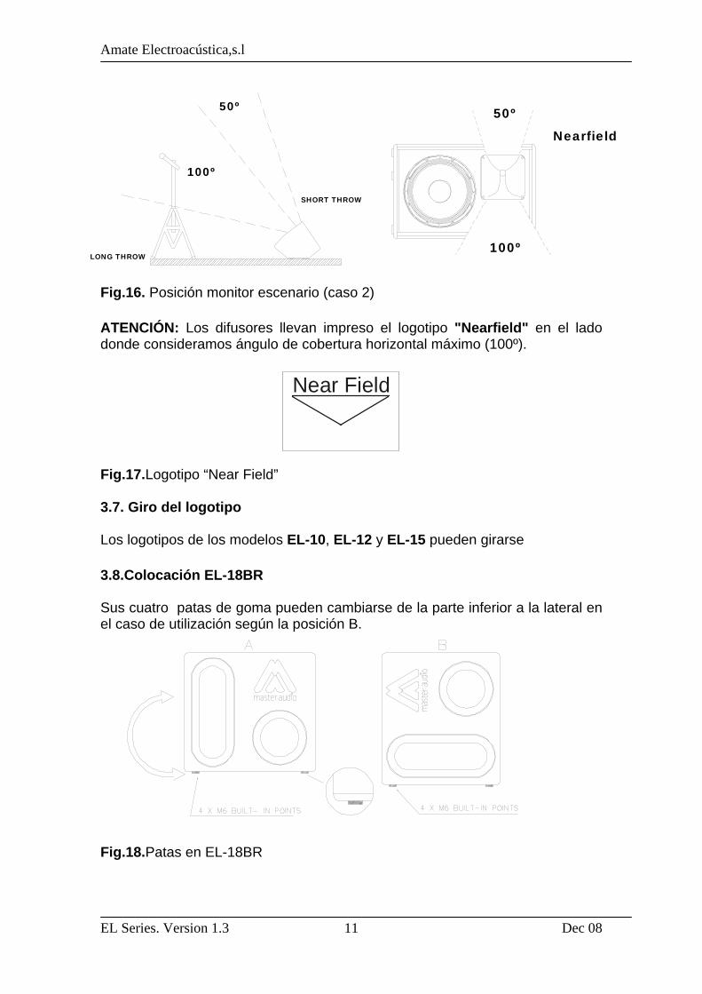
Fig.15. Posición monitor escenario (caso 1) Caso 2 Nos interesa mantener una cobertura más estrecha (50º) en el campo cercano del cantante y una cobertura más ancha (100º) a medida que el cantante se aleja (escenarios alargados).
50º
100º
SHORT THROW
LONG THROW
50º
100ºNearfield
100º
50º
LONG THROW
SHORT THROW
Amate Electroacústica,s.l
EL Series. Version 1.3 Dec 08
11
100º
50º
LONG THROW
SHORT THROW
100º
50º
Nearfield
Fig.16. Posición monitor escenario (caso 2) ATENCIÓN: Los difusores llevan impreso el logotipo "Nearfield" en el lado donde consideramos ángulo de cobertura horizontal máximo (100º). Fig.17.Logotipo “Near Field” 3.7. Giro del logotipo Los logotipos de los modelos EL-10, EL-12 y EL-15 pueden girarse 3.8.Colocación EL-18BR Sus cuatro patas de goma pueden cambiarse de la parte inferior a la lateral en el caso de utilización según la posición B. Fig.18.Patas en EL-18BR
Near Field
Amate Electroacústica,s.l
EL Series. Version 1.3 Dec 08
12
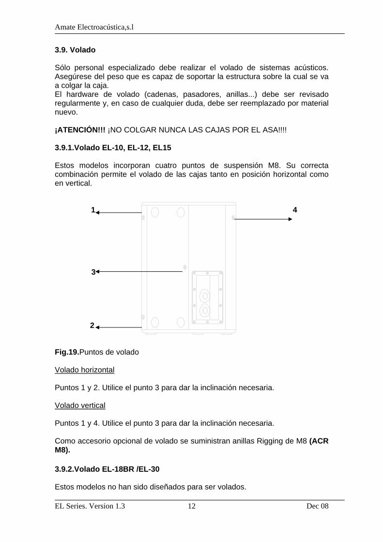
3.9. Volado Sólo personal especializado debe realizar el volado de sistemas acústicos. Asegúrese del peso que es capaz de soportar la estructura sobre la cual se va a colgar la caja. El hardware de volado (cadenas, pasadores, anillas...) debe ser revisado regularmente y, en caso de cualquier duda, debe ser reemplazado por material nuevo. ¡ATENCIÓN!!! ¡NO COLGAR NUNCA LAS CAJAS POR EL ASA!!!! 3.9.1.Volado EL-10, EL-12, EL15 Estos modelos incorporan cuatro puntos de suspensión M8. Su correcta combinación permite el volado de las cajas tanto en posición horizontal como en vertical.
1 4 3
2 Fig.19.Puntos de volado Volado horizontal Puntos 1 y 2. Utilice el punto 3 para dar la inclinación necesaria. Volado vertical Puntos 1 y 4. Utilice el punto 3 para dar la inclinación necesaria. Como accesorio opcional de volado se suministran anillas Rigging de M8 (ACR M8). 3.9.2.Volado EL-18BR /EL-30 Estos modelos no han sido diseñados para ser volados.

Amate Electroacústica,s.l
EL Series. Version 1.3 Dec 08
13
3.9.3.Soporte "U" modelo U-N10 (Opcional) Opcionalmente, puede adquirirse soporte en forma de "U" para el modelo EL-10. El soporte debe ir siempre montado con sus correspondientes roscas y permite el colgado tanto en posición horizontal como en vertical. 1 2 5 3 4 1 Fig.20.Soporte UN-10 Colgado: 1- Sitúe el soporte cerca de la pared donde vaya a colgar la caja y marque la localización de los puntos de soporte (1). 2- Realice los taladros en la pared y cuelgue el soporte con tornillería adecuada.(incluida en el kit). 3- Cambiar el vaso para trípode que incorpora la caja de serie en la parte inferior por la pletina suministrada en el kit (2). 4- Coloque la caja entre el soporte y fíjela con las dos roscas de M8 que incorpora el kit. El orden de colocación de los accesorios es el siguiente: a) Arandela de goma (3) b) Soporte U-N10 c) Roscas de M8 (4) 5- Ajuste la caja a la posición y ángulo deseado. Es posible añadir cable de acero de 2mm a través del punto (5) para asegurar aún más el soporte.
Amate Electroacústica,s.l
EL Series. Version 1.3 Dec 08
14
4. ESPECIFICACIONES 4.1. Especificaciones EL-10 Impedancia 8Ω Sensibilidad 1W/1m 96dB Respuesta en frecuencia (-10 dB) 55Hz-20kHz Capacidad de potencia R.M.S 150W Programa 300W Directividad nominal (-6dB) Horizontal 50º a 100º (difusor rotativo) Vertical 55º Componentes LF 1x10" woofer HF 1x motor con diafragma de titanio (bobina 1.5”) Recinto Altura 507mm Anchura 364 mm Profundidad 326 mm Peso (neto) 13Kg Conectores 2 x Speakon (IN/LINK) Material Tablero abedul, Reja frontal de acero pintada epoxy negra
con espuma acústicamente transparente Acabado Pintura negra de resinas acrílicas, ecológica a base de
agua 4.2. Especificaciones EL-12 Impedancia 8Ω Sensibilidad 1W/1m 98dB Respuesta en frecuencia (-10 dB) 50Hz-20kHz Capacidad de potencia R.M.S 200W Programa 400W Directividad nominal (-6dB) Horizontal 50º a 100º (difusor rotativo) Vertical 55º
Amate Electroacústica,s.l
EL Series. Version 1.3 Dec 08
15
Componentes LF 1x12" woofer HF 1x motor con diafragma de titanio (bobina 1.5”) Recinto Altura 627mm Anchura 412 mm Profundidad 401 mm Peso (neto) 19.3Kg Conectores 2 x Speakon (IN/LINK) Material Tablero abedul, Reja frontal de acero pintada epoxy negra
con espuma acústicamente transparente Acabado Pintura negra de resinas acrílicas, ecológica a base de
agua 4.3. Especificaciones EL-15 Impedancia 8Ω Sensibilidad 1W/1m 99dB Respuesta en frecuencia (-10 dB) 48Hz-20kHz Capacidad de potencia R.M.S 250W Programa 500W Directividad nominal (-6dB) Horizontal 50º a 100º (difusor rotativo) Vertical 55º Componentes LF 1x15" woofer HF 1x motor con diafragma de titanio (bobina 1.5”) Recinto Altura 727mm Anchura 471 mm Profundidad 455 mm Peso (neto) 25.2Kg Conectores 2 x Speakon (IN/LINK) Material Tablero abedul, Reja frontal de acero pintada epoxy negra
con espuma acústicamente transparente Acabado Pintura negra de resinas acrílicas, ecológica a base de
agua
Amate Electroacústica,s.l
EL Series. Version 1.3 Dec 08
16
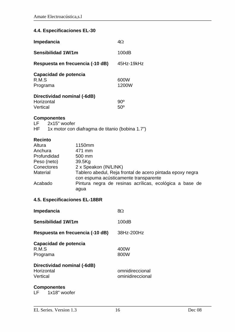
4.4. Especificaciones EL-30 Impedancia 4Ω Sensibilidad 1W/1m 100dB Respuesta en frecuencia (-10 dB) 45Hz-19kHz Capacidad de potencia R.M.S 600W Programa 1200W Directividad nominal (-6dB) Horizontal 90º Vertical 50º Componentes LF 2x15" woofer HF 1x motor con diafragma de titanio (bobina 1.7”) Recinto Altura 1150mm Anchura 471 mm Profundidad 500 mm Peso (neto) 39.5Kg Conectores 2 x Speakon (IN/LINK) Material Tablero abedul, Reja frontal de acero pintada epoxy negra
con espuma acústicamente transparente Acabado Pintura negra de resinas acrílicas, ecológica a base de
agua 4.5. Especificaciones EL-18BR Impedancia 8Ω Sensibilidad 1W/1m 100dB Respuesta en frecuencia (-10 dB) 38Hz-200Hz Capacidad de potencia R.M.S 400W Programa 800W Directividad nominal (-6dB) Horizontal omnidireccional Vertical ominidireccional Componentes LF 1x18" woofer
Amate Electroacústica,s.l
EL Series. Version 1.3 Dec 08
17
Recinto Altura 512mm Anchura 635 mm Profundidad 512 mm Peso (neto) 31.3Kg Conectores 2 x Speakon (IN/LINK) Material Tablero abedul Acabado Pintura negra de resinas acrílicas, ecológica a base de
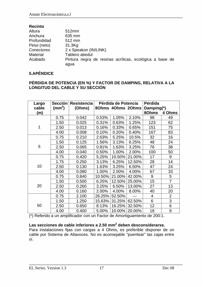
agua 5.APÉNDICE PÉRDIDA DE POTENCIA (EN %) Y FACTOR DE DAMPING, RELATIVA A LA LONGITUD DEL CABLE Y SU SECCIÓN
(*) Referido a un amplificador con un Factor de Amortiguamiento de 200:1. Las secciones de cable inferiores a 2.50 mm2 deben desconsiderarse. Para instalaciones fijas con cargas a 4 Ohms, es preferible disponer de un cable por Sistema de Altavoces. No es aconsejable "puentear" las cajas entre sí.
Largo cable (m)
Sección (mm2)
Resistencia (Ohms)
Pérdida de Potencia 8Ohms 4Ohms 2Ohms
Pérdida Damping(*) 8Ohms 4 Ohms
0.75 0.042 0.53% 1.05% 2.10% 98 49 1.50 0.025 0.31% 0.63% 1.25% 123 62 2.50 0.013 0.16% 0.33% 0.65% 151 75
1 4.00 0.008 0.10% 0.20% 0.40% 167 83
0.75 0.210 2.63% 5.25% 10.5% 32 16 1.50 0.125 1.56% 3.13% 6.25% 48 24 2.50 0.065 0.81% 1.63% 3.25% 76 38
5 4.00 0.040 0.50% 1.00% 2.00% 100 50
0.75 0.420 5.25% 10.50% 21.00% 17 9 1.75 0.250 3.13% 6.25% 12.50% 28 14 2.50 0.130 1.63% 3.25% 6.50% 47 24
10 4.00 0.080 1.00% 2.00% 4.00% 67 33
0.75 0.840 10.50% 21.00% 42.00% 9 5 1.50 0.500 6.25% 12.50% 25.00% 15 7 2.50 0.260 3.25% 6.50% 13.00% 27 13
20 4.00 0.160 2.00% 4.00% 8.00% 40 20
0.75 2.100 26.25% 52.50% --- 4 2 1.50 1.250 15.63% 31.25% 62.50% 6 3 2.50 0.650 8.13% 16.25% 32.50% 12 6
50 4.00 0.400 5.00% 10.00% 20.00% 18 9
Amate Electroacústica,s.l
EL Series. Version 1.3 Dec 08
18
ENGLISH 1.INTRODUCTION 1.1.General Amate Electroacústica, s.l. would like to thank you for your confidence in our new EL Series. We suggest you to carefully read the following instructions in order to obtain the best results in performance. 1.2.Features and presentation EL-10 - Two Way Full Range Speaker System - 10" High Performance Woofer - 1" ½ Titanium diaphragm Driver - 50º to 100º(H) x 55º(V) asymmetrical dispersion horn - Accurate designed Crossover to achieve the best performance - Power Handling : 150 W r.m.s - Sensitivity : 96 dB (1W/1m) EL-12
- Two Way Full Range Speaker System - 12" High Performance Woofer - 1" ½ Titanium diaphragm Driver - 50º to 100º(H) x 55º(V) asymmetrical dispersion horn - Accurate designed Crossover to achieve the best performance - Power Handling : 200 W r.m.s - Sensitivity : 98 dB (1W/1m)
EL-15 - Two Way Full Range Speaker System - 15" High Performance Woofer - 1" ½ Titanium diaphragm Driver - 50º to 100º(H) x 55º(V) asymmetrical dispersion horn - Accurate designed Crossover to achieve the best performance - Power Handling : 250 W r.m.s - Sensitivity : 99 dB (1W/1m)
EL-30 - Two Way Full Range Speaker System - 2 x 15" High Performance Woofers - 1" 3/4 Titanium diaphragm Driver - 90º(H) x 50º(V) constant directivity horn.
Amate Electroacústica,s.l
EL Series. Version 1.3 Dec 08
19
- Accurate designed Crossover to achieve the best performance - Power Handling : 600 W r.m.s - Sensitivity : 100 dB (1W/1m) EL-18BR
- Low frequency reinforcement unit - 18" High Performance Woofer
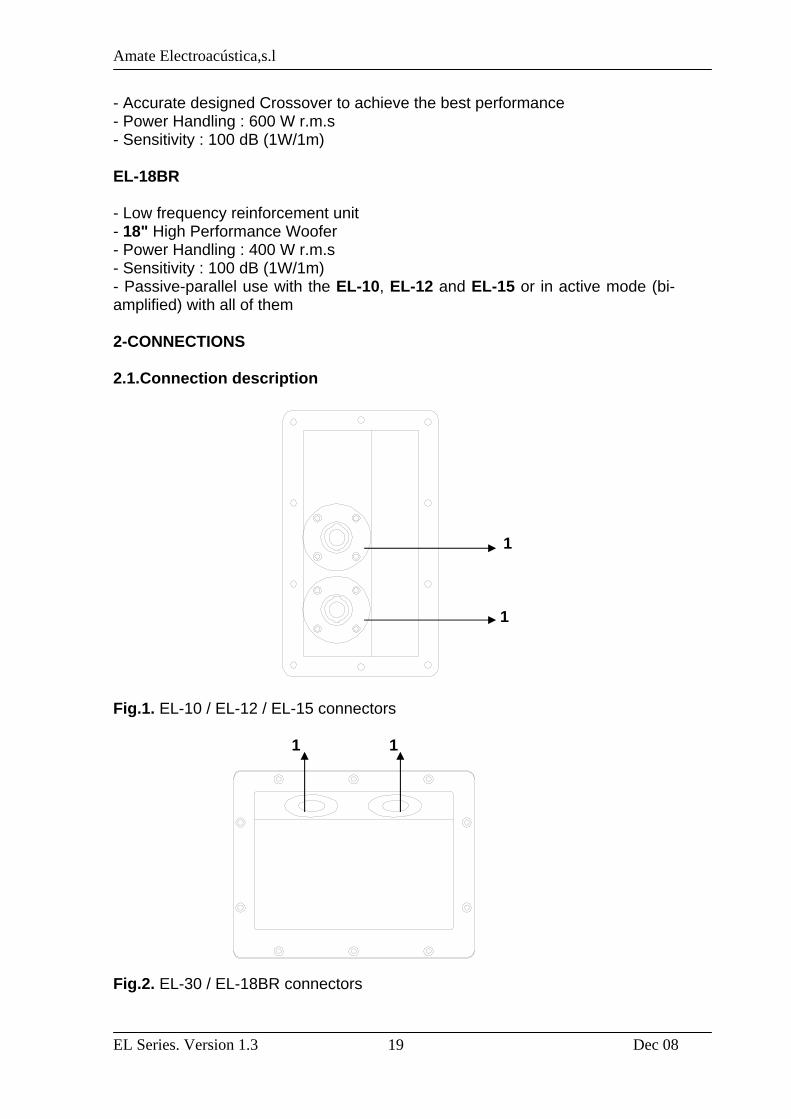
- Power Handling : 400 W r.m.s - Sensitivity : 100 dB (1W/1m) - Passive-parallel use with the EL-10, EL-12 and EL-15 or in active mode (bi-amplified) with all of them 2-CONNECTIONS 2.1.Connection description 1 1 Fig.1. EL-10 / EL-12 / EL-15 connectors
1 1
Fig.2. EL-30 / EL-18BR connectors
Amate Electroacústica,s.l
EL Series. Version 1.3 Dec 08
20
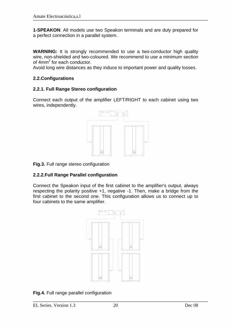
1-SPEAKON: All models use two Speakon terminals and are duly prepared for a perfect connection in a parallel system. WARNING: It is strongly recommended to use a two-conductor high quality wire, non-shielded and two-coloured. We recommend to use a minimum section of 4mm2 for each conductor. Avoid long wire distances as they induce to important power and quality losses. 2.2.Configurations 2.2.1. Full Range Stereo configuration Connect each output of the amplifier LEFT/RIGHT to each cabinet using two wires, independently. Fig.3. Full range stereo configuration 2.2.2.Full Range Parallel configuration Connect the Speakon input of the first cabinet to the amplifier's output, always respecting the polarity positive +1, negative -1. Then, make a bridge from the first cabinet to the second one. This configuration allows us to connect up to four cabinets to the same amplifier. Fig.4. Full range parallel configuration
Amate Electroacústica,s.l
EL Series. Version 1.3 Dec 08
21
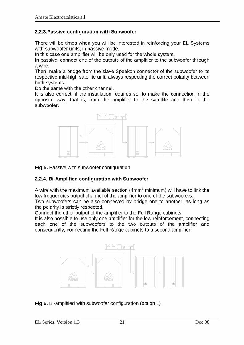
2.2.3.Passive configuration with Subwoofer There will be times when you will be interested in reinforcing your EL Systems with subwoofer units, in passive mode. In this case one amplifier will be only used for the whole system. In passive, connect one of the outputs of the amplifier to the subwoofer through a wire. Then, make a bridge from the slave Speakon connector of the subwoofer to its respective mid-high satellite unit, always respecting the correct polarity between both systems. Do the same with the other channel. It is also correct, if the installation requires so, to make the connection in the opposite way, that is, from the amplifier to the satellite and then to the subwoofer. Fig.5. Passive with subwoofer configuration 2.2.4. Bi-Amplified configuration with Subwoofer A wire with the maximum available section (4mm2 minimum) will have to link the low frequencies output channel of the amplifier to one of the subwoofers. Two subwoofers can be also connected by bridge one to another, as long as the polarity is strictly respected. Connect the other output of the amplifier to the Full Range cabinets. It is also possible to use only one amplifier for the low reinforcement, connecting each one of the subwoofers to the two outputs of the amplifier and consequently, connecting the Full Range cabinets to a second amplifier. Fig.6. Bi-amplified with subwoofer configuration (option 1)
Amate Electroacústica,s.l
EL Series. Version 1.3 Dec 08
22
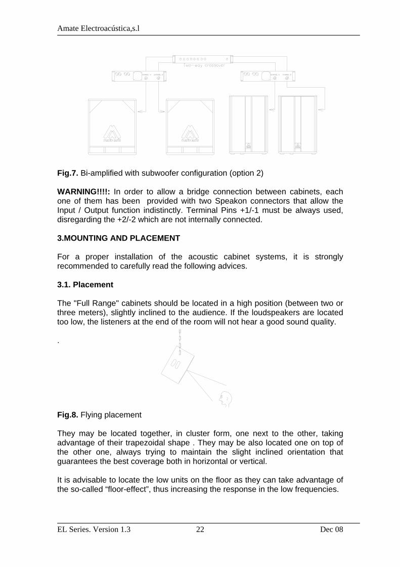
Fig.7. Bi-amplified with subwoofer configuration (option 2) WARNING!!!!: In order to allow a bridge connection between cabinets, each one of them has been provided with two Speakon connectors that allow the Input / Output function indistinctly. Terminal Pins +1/-1 must be always used, disregarding the +2/-2 which are not internally connected. 3.MOUNTING AND PLACEMENT For a proper installation of the acoustic cabinet systems, it is strongly recommended to carefully read the following advices. 3.1. Placement The "Full Range" cabinets should be located in a high position (between two or three meters), slightly inclined to the audience. If the loudspeakers are located too low, the listeners at the end of the room will not hear a good sound quality. . Fig.8. Flying placement They may be located together, in cluster form, one next to the other, taking advantage of their trapezoidal shape . They may be also located one on top of the other one, always trying to maintain the slight inclined orientation that guarantees the best coverage both in horizontal or vertical. It is advisable to locate the low units on the floor as they can take advantage of the so-called “floor-effect”, thus increasing the response in the low frequencies.

Amate Electroacústica,s.l
EL Series. Version 1.3 Dec 08
23
If possible, place the subwoofers under the same acoustic axis used for the satellites. If the above option can not be carried out, then they should be placed in an intermediate point between the left and right channels. 3.2. Tripod use The EL-10, EL-12 and EL-15 models are equipped with a tripod socket for use with Standard 35mm tripods. Do not use the tripod on non-flat floors and be careful not to raise the cabinet too high on the tripod, as it may become unstable. 3.3.Full range cabinet + subwoofer use The EL-18BR is equipped with a M20 Plate for a 35mm distance Rod. We can use it to place over the subwoofer the models that are equipped with the tripod socket (EL-10, EL-12 and EL-15). Be careful not to use this system on non-flat surfaces as it may become unstable. Fig.9. Full range cabinet with subwoofer 3.4. Stage monitor use The EL-10, EL-12 and EL-15 models have trapezoidal shape so, they can be used as floor monitors without extra accessories. Fig.10. Stage monitor use
41º
Amate Electroacústica,s.l
EL Series. Version 1.3 Dec 08
24
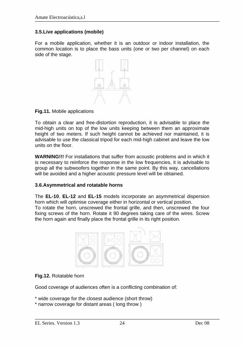
3.5.Live applications (mobile) For a mobile application, whether it is an outdoor or indoor installation, the common location is to place the bass units (one or two per channel) on each side of the stage. Fig.11. Mobile applications To obtain a clear and free-distortion reproduction, it is advisable to place the mid-high units on top of the low units keeping between them an approximate height of two meters. If such height cannot be achieved nor maintained, it is advisable to use the classical tripod for each mid-high cabinet and leave the low units on the floor. WARNING!!! For installations that suffer from acoustic problems and in which it is necessary to reinforce the response in the low frequencies, it is advisable to group all the subwoofers together in the same point. By this way, cancellations will be avoided and a higher acoustic pressure level will be obtained. 3.6.Asymmetrical and rotatable horns The EL-10, EL-12 and EL-15 models incorporate an asymmetrical dispersion horn which will optimise coverage either in horizontal or vertical position. To rotate the horn, unscrewed the frontal grille, and then, unscrewed the four fixing screws of the horn. Rotate it 90 degrees taking care of the wires. Screw the horn again and finally place the frontal grille in its right position. Fig.12. Rotatable horn Good coverage of audiences often is a conflicting combination of: * wide coverage for the closest audience (short throw) * narrow coverage for distant areas ( long throw )
Amate Electroacústica,s.l
EL Series. Version 1.3 Dec 08
25
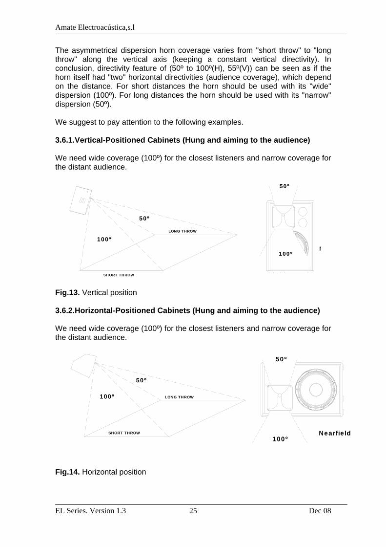
The asymmetrical dispersion horn coverage varies from "short throw" to "long throw" along the vertical axis (keeping a constant vertical directivity). In conclusion, directivity feature of (50º to 100º(H), 55º(V)) can be seen as if the horn itself had "two" horizontal directivities (audience coverage), which depend on the distance. For short distances the horn should be used with its "wide" dispersion (100º). For long distances the horn should be used with its "narrow" dispersion (50º). We suggest to pay attention to the following examples. 3.6.1.Vertical-Positioned Cabinets (Hung and aiming to the audience) We need wide coverage (100º) for the closest listeners and narrow coverage for the distant audience. Fig.13. Vertical position 3.6.2.Horizontal-Positioned Cabinets (Hung and aiming to the audience) We need wide coverage (100º) for the closest listeners and narrow coverage for the distant audience. Fig.14. Horizontal position
100º
50º
LONG THROW
SHORT THROW
50º
N100º
50º
100ºNearfield
50º
100º
SHORT THROW
LONG THROW

Amate Electroacústica,s.l
EL Series. Version 1.3 Dec 08
26
50º
Nearfield
100º
50º
LONG THROW
SHORT THROW
100º
50º
Nearfield
3.6.3.Stage monitor use Case 1 We need wider coverage (100º) when performers are close to the cabinet than when they move away from it (50º).
Fig.15. Stage monitor use (case 1) Case 2
We need wider coverage (100º) when performers move away from the cabinet (long stages) than when they are close to it (50º). Fig.16. Stage monitor use (case 2) WARNING: The horns have the "Near field" mark printed on the 100º horizontal coverage side.
100º
50º
LONG THROW
SHORT THROW

Amate Electroacústica,s.l
EL Series. Version 1.3 Dec 08
27
Fig.17. “Near Field” logo
3.7. Rotatable logo EL-10, EL-12 and EL-15 model marks can be rotated. 3.8. EL-18BR Position Rubber feet can be removed from the bottom to the side of the cabinet in case of B position. Fig.18.Rubber feet on EL-18BR 3.9. Flying Only experienced people should fly speaker cabinets. Extreme care should be taken to assure the load bearing capabilities of the structures where the cabinets will be placed. Hanging hardware (as chains, eyebolt, Lock Pins...) should be regularly inspected and replaced if in doubt. WARNING!!! DO NOT SUSPEND THE CABINETS FROM THE HANDLES!!!! 3.9.1. EL-10, EL-12, EL15 Flying These models provide four M8 flying points. Its correct use will permit the flying in horizontal or vertical position.
Near Field

Amate Electroacústica,s.l
EL Series. Version 1.3 Dec 08
28
1 4 3
2 Fig.19.Flying points Horizontal Flying Points 1 and 2. Use point 3 to get the desired inclination. Vertical Flying Points 1 and 4. Use point 3 to get the desired inclination. We offer as optional accessory the forged eyebolt rigging M8 (ACR M8). 3.9.2. EL-18BR / EL-30 Flying These models are not prepared for flying. 3.9.3.Bracket U-N10 (Optional) The EL-10 can optionally incorporate a "U" bracket which allows the cabinet to be mounted on a wall or ceiling. The bracket may be mounted with either nails or screws, horizontally or vertically. 1 2 5 3 4 1 Fig.20. UN-10 bracket
Amate Electroacústica,s.l
EL Series. Version 1.3 Dec 08
29
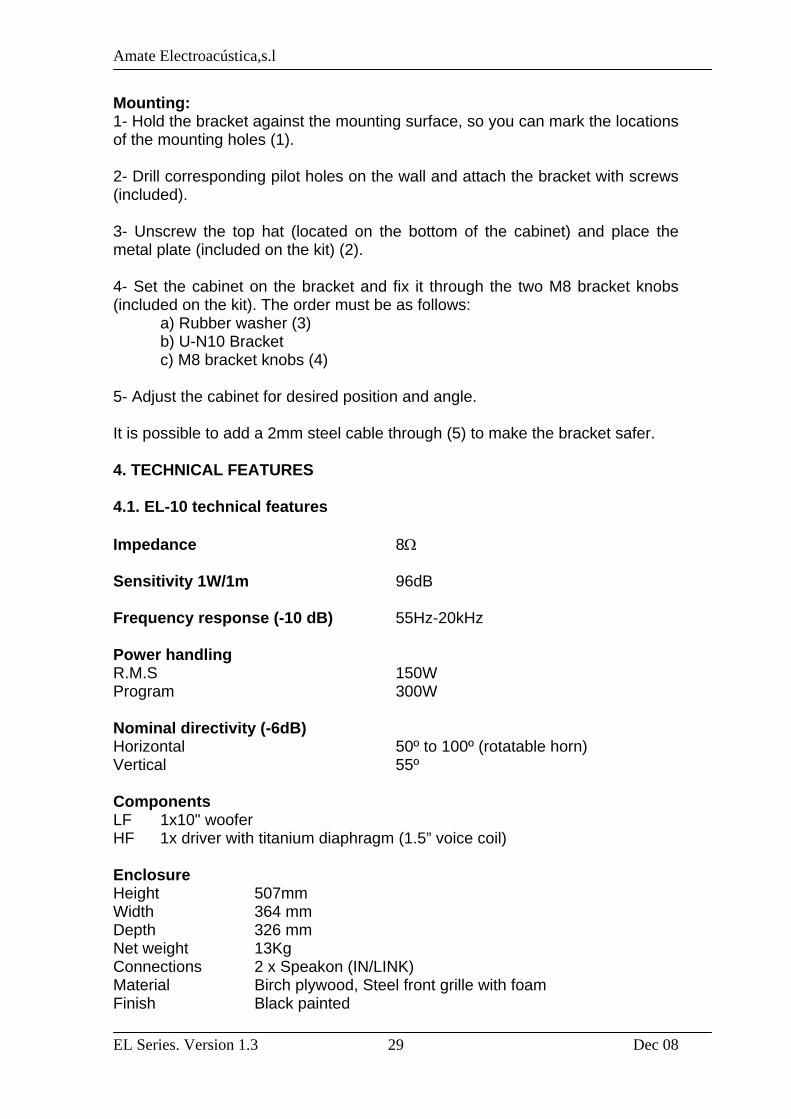
Mounting: 1- Hold the bracket against the mounting surface, so you can mark the locations of the mounting holes (1). 2- Drill corresponding pilot holes on the wall and attach the bracket with screws (included). 3- Unscrew the top hat (located on the bottom of the cabinet) and place the metal plate (included on the kit) (2). 4- Set the cabinet on the bracket and fix it through the two M8 bracket knobs (included on the kit). The order must be as follows: a) Rubber washer (3) b) U-N10 Bracket c) M8 bracket knobs (4) 5- Adjust the cabinet for desired position and angle. It is possible to add a 2mm steel cable through (5) to make the bracket safer. 4. TECHNICAL FEATURES 4.1. EL-10 technical features Impedance 8Ω Sensitivity 1W/1m 96dB Frequency response (-10 dB) 55Hz-20kHz Power handling R.M.S 150W Program 300W Nominal directivity (-6dB) Horizontal 50º to 100º (rotatable horn) Vertical 55º Components LF 1x10" woofer HF 1x driver with titanium diaphragm (1.5” voice coil) Enclosure Height 507mm Width 364 mm Depth 326 mm Net weight 13Kg Connections 2 x Speakon (IN/LINK) Material Birch plywood, Steel front grille with foam Finish Black painted
Amate Electroacústica,s.l
EL Series. Version 1.3 Dec 08
30
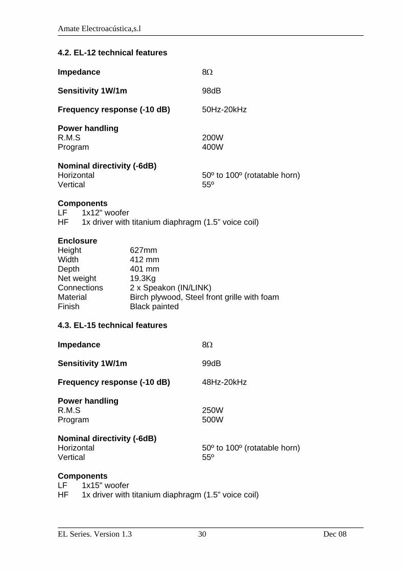
4.2. EL-12 technical features Impedance 8Ω Sensitivity 1W/1m 98dB Frequency response (-10 dB) 50Hz-20kHz Power handling R.M.S 200W Program 400W Nominal directivity (-6dB) Horizontal 50º to 100º (rotatable horn) Vertical 55º Components LF 1x12" woofer HF 1x driver with titanium diaphragm (1.5” voice coil) Enclosure Height 627mm Width 412 mm Depth 401 mm Net weight 19.3Kg Connections 2 x Speakon (IN/LINK) Material Birch plywood, Steel front grille with foam Finish Black painted 4.3. EL-15 technical features Impedance 8Ω Sensitivity 1W/1m 99dB Frequency response (-10 dB) 48Hz-20kHz Power handling R.M.S 250W Program 500W Nominal directivity (-6dB) Horizontal 50º to 100º (rotatable horn) Vertical 55º Components LF 1x15" woofer HF 1x driver with titanium diaphragm (1.5” voice coil)
Amate Electroacústica,s.l
EL Series. Version 1.3 Dec 08
31
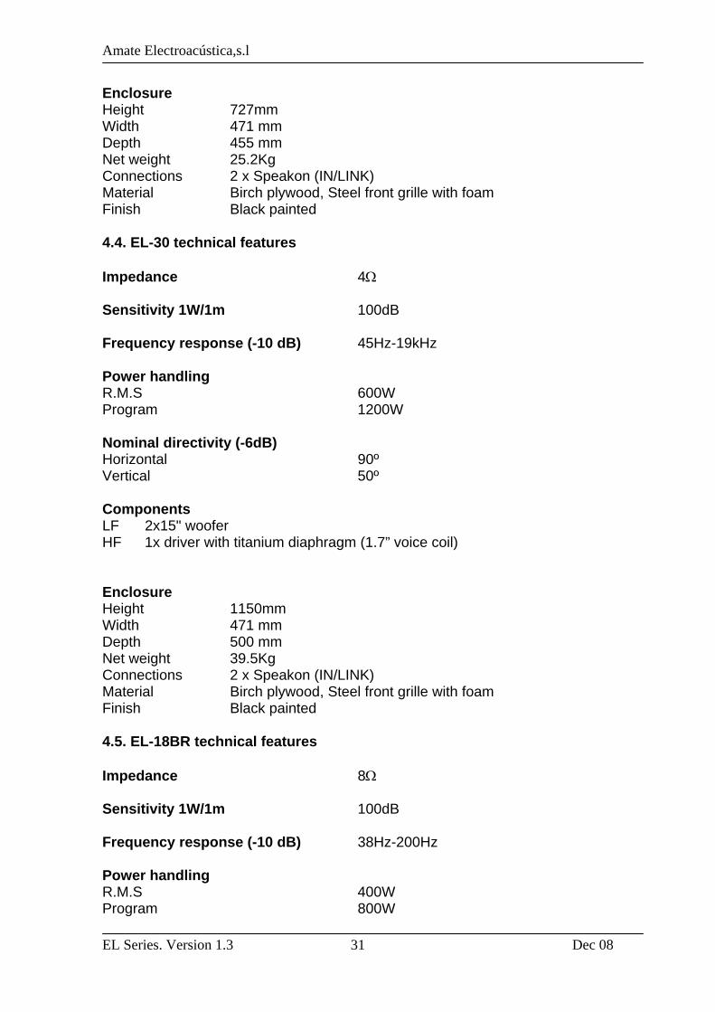
Enclosure Height 727mm Width 471 mm Depth 455 mm Net weight 25.2Kg Connections 2 x Speakon (IN/LINK) Material Birch plywood, Steel front grille with foam Finish Black painted 4.4. EL-30 technical features Impedance 4Ω Sensitivity 1W/1m 100dB Frequency response (-10 dB) 45Hz-19kHz Power handling R.M.S 600W Program 1200W Nominal directivity (-6dB) Horizontal 90º Vertical 50º Components LF 2x15" woofer HF 1x driver with titanium diaphragm (1.7” voice coil) Enclosure Height 1150mm Width 471 mm Depth 500 mm Net weight 39.5Kg Connections 2 x Speakon (IN/LINK) Material Birch plywood, Steel front grille with foam Finish Black painted 4.5. EL-18BR technical features Impedance 8Ω Sensitivity 1W/1m 100dB Frequency response (-10 dB) 38Hz-200Hz Power handling R.M.S 400W Program 800W
Amate Electroacústica,s.l
EL Series. Version 1.3 Dec 08
32
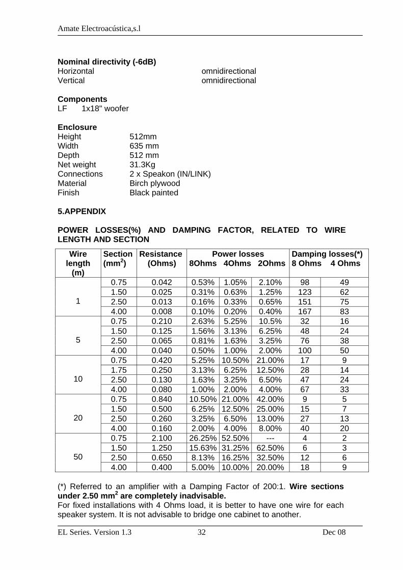
Nominal directivity (-6dB) Horizontal omnidirectional Vertical omnidirectional Components LF 1x18" woofer Enclosure Height 512mm Width 635 mm Depth 512 mm Net weight 31.3Kg Connections 2 x Speakon (IN/LINK) Material Birch plywood Finish Black painted 5.APPENDIX POWER LOSSES(%) AND DAMPING FACTOR, RELATED TO WIRE LENGTH AND SECTION
(*) Referred to an amplifier with a Damping Factor of 200:1. Wire sections under 2.50 mm2 are completely inadvisable. For fixed installations with 4 Ohms load, it is better to have one wire for each speaker system. It is not advisable to bridge one cabinet to another.
Wire length
(m)
Section (mm2)
Resistance(Ohms)
Power losses 8Ohms 4Ohms 2Ohms
Damping losses(*) 8 Ohms 4 Ohms
0.75 0.042 0.53% 1.05% 2.10% 98 49 1.50 0.025 0.31% 0.63% 1.25% 123 62 2.50 0.013 0.16% 0.33% 0.65% 151 75
1 4.00 0.008 0.10% 0.20% 0.40% 167 83
0.75 0.210 2.63% 5.25% 10.5% 32 16 1.50 0.125 1.56% 3.13% 6.25% 48 24 2.50 0.065 0.81% 1.63% 3.25% 76 38
5 4.00 0.040 0.50% 1.00% 2.00% 100 50
0.75 0.420 5.25% 10.50% 21.00% 17 9 1.75 0.250 3.13% 6.25% 12.50% 28 14 2.50 0.130 1.63% 3.25% 6.50% 47 24
10 4.00 0.080 1.00% 2.00% 4.00% 67 33
0.75 0.840 10.50% 21.00% 42.00% 9 5 1.50 0.500 6.25% 12.50% 25.00% 15 7 2.50 0.260 3.25% 6.50% 13.00% 27 13
20 4.00 0.160 2.00% 4.00% 8.00% 40 20
0.75 2.100 26.25% 52.50% --- 4 2 1.50 1.250 15.63% 31.25% 62.50% 6 3 2.50 0.650 8.13% 16.25% 32.50% 12 6
50 4.00 0.400 5.00% 10.00% 20.00% 18 9