Central Con Presa
67
B. Leist H. Evers W. Leech J. Kroyer June 12, 2007 B. Leist H. Evers W. Leech J. Kroyer June 12, 2007 Kárahnjúkar HEP Extreme Underground Construction Kárahnjúkar HEP Extreme Underground Construction
-
Upload
jdonosov1579 -
Category
Documents
-
view
245 -
download
2
Transcript of Central Con Presa
B. LeistH. EversW. LeechJ. KroyerJune 12, 2007
B. LeistH. EversW. LeechJ. KroyerJune 12, 2007
Kárahnjúkar HEP
Extreme Underground ConstructionKárahnjúkar HEP
Extreme Underground Construction
Project Overview
Design
Construction
Conclusions
Project Overview
− Project location
− Key figures
− Tunnel alignment

Snæ-fell
Eyja-bakkar
12.2003
Jökulsá á DalFjarðaál
Egilsstaðir
Reyðarfjörður
FL 3&42x220 kV
Laga
rfljót
Þrándar-jökull
Mývatn
Jöku
lsáá Fjöllum
Ódáðahraun
Jökuldals-heiði
Krafla60 MW
Bjarnarflag3 MW
Héraðs-flói
Brúar-öræfi
Vestur-öræfi
Askja
Herðu-breið
Krep
pa
Kverkfjöll Hraun
Dyngjujökull
Kröflulína 2132 kV
132 kV
132 kV
Kárahnjúkar HEP690 MW
Kára-hnjúkar
Headracetunnel
Jöku
lsáí F
ljótsd
al
Hálslónreservoir
KárahnjúkarPowerhouse
Kelduárlónreservoir
V A T N A J Ö K U L L G L A C I E R
BrúarjökullGlacier
Ufsarlónreservoir N

Kárahnjúkar HEP800 m a.s.l.
Pressure shaftHeadrace tunnel
Power station26,5
m a.s.l.
625 m a.s.l.Kárahnjúkar dam Longitude section
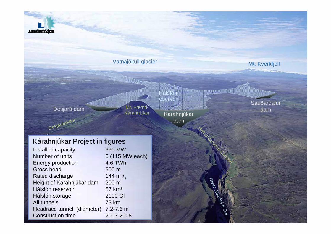
Mt. Fremri-Kárahnjúkur
Sauðárdalurdam
River Jökulsáá
Dal
Hafrahvammar Canyon
Desjarárdalur
Mt. KverkfjöllVatnajökull glacier
Kárahnjúkardam
Desjará dam
Hálslónreservoir
Installed capacity 690 MWNumber of units 6 (115 MW each)Energy production 4.6 TWhGross head 600 mRated discharge 144 m3/sHeight of Kárahnjúkar dam 200 mHálslón reservoir 57 km²Hálslón storage 2100 GlAll tunnels 73 kmHeadrace tunnel (diameter) 7.2-7.6 mConstruction time 2003-2008
Kárahnjúkar Project in figures
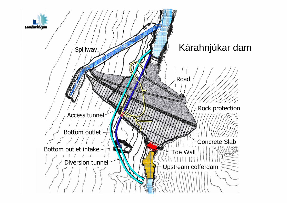
Spillway
Upstream cofferdam
Concrete Slab
Road
Rock protection
Diversion tunnel
Toe WallBottom outlet intake
Access tunnel
Bottom outlet
Kárahnjúkar dam
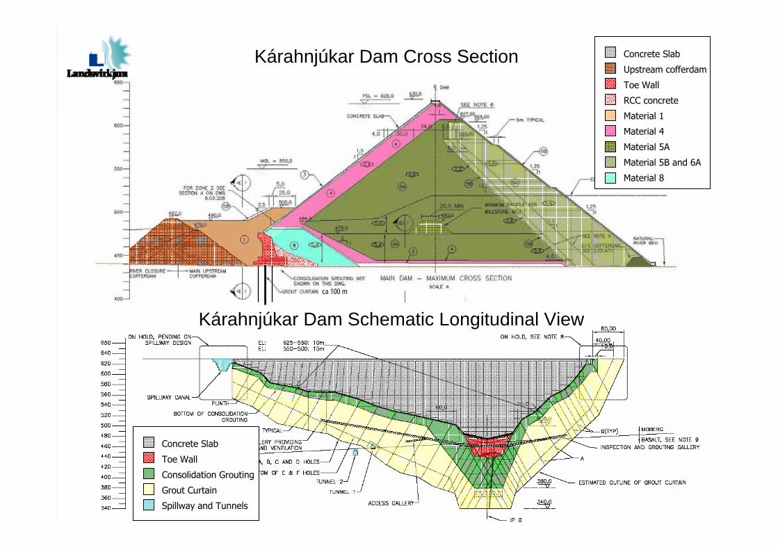
ca 100 m
Kárahnjúkar Dam Cross Section
Kárahnjúkar Dam Schematic Longitudinal View
Concrete Slab
Upstream cofferdam
Toe Wall
RCC concrete
Material 1
Material 4
Material 5A
Material 5B and 6A
Material 8
Concrete Slab
Toe Wall
Consolidation Grouting
Grout Curtain
Spillway and Tunnels
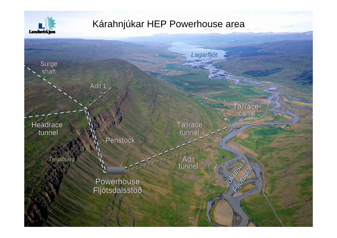
Jöku
lsáí
Fljót
sdal
Jöku
lsáí
Fljót
sdal
Lagarfljót
TeigsbjargTeigsbjarg
ValþjófsstaðurValþjófsstaður
PenstockPenstock
PowerhouseFljótsdalsstöðPowerhouseFljótsdalsstöð
Adit 1Adit 1
Headracetunnel
Headracetunnel
Tailracetunnel
Tailracetunnel
Tailrace-canal
Tailrace-canal
Surgeshaft
Surgeshaft
Kárahnjúkar HEP Powerhouse area
AdittunnelAdit
tunnel
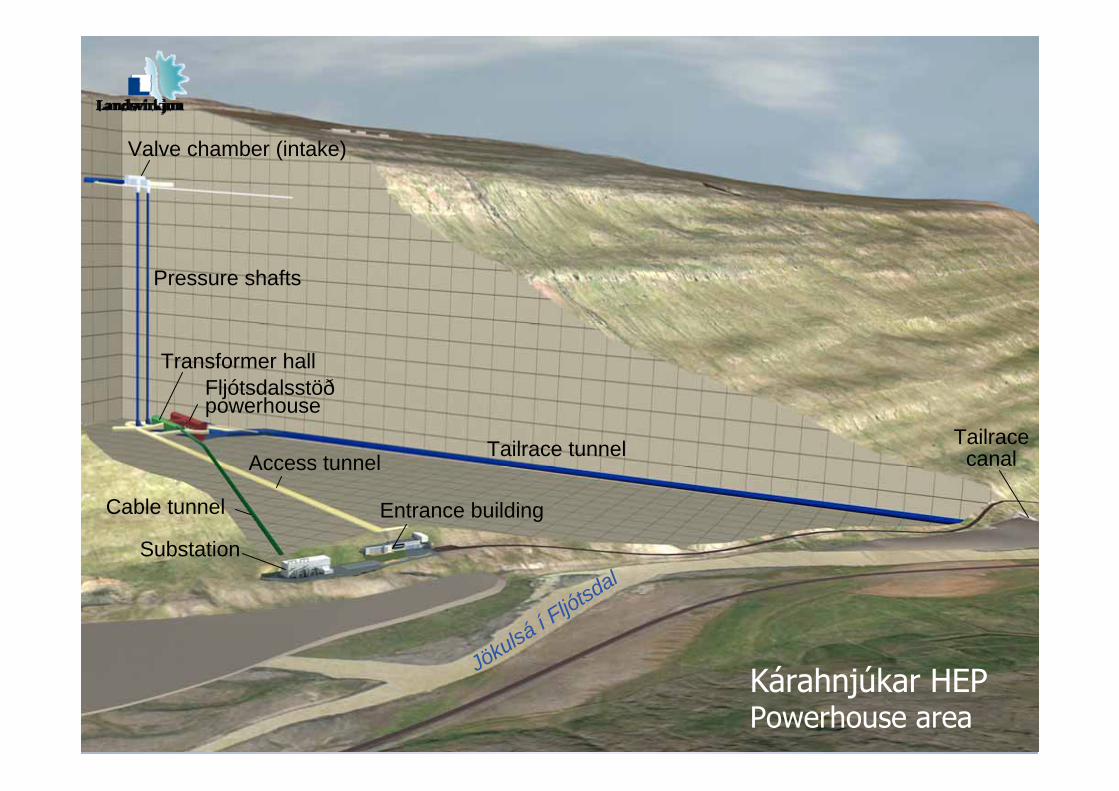
Kárahnjúkar HEPPowerhouse area
Substation
Tailrace tunnel
Entrance buildingCable tunnel
Access tunnel
Fljótsdalsstöðpowerhouse
Pressure shafts
Transformer hall
Valve chamber (intake)
Jökulsá í Fljótsdal
Tailracecanal
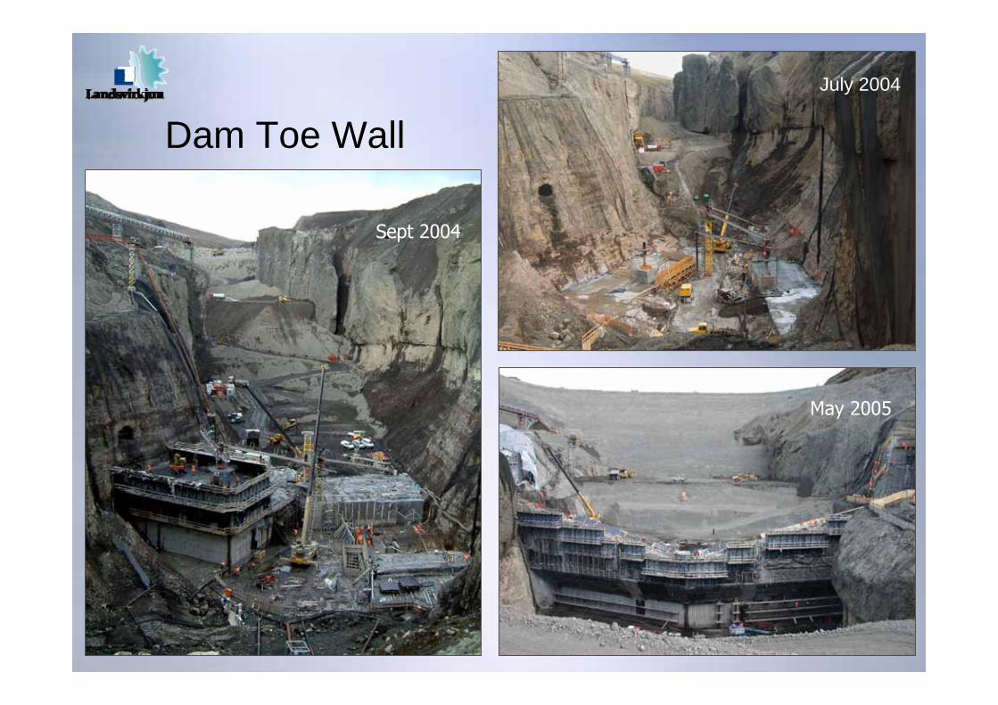
Dam Toe WallJuly 2004
Sept 2004
May 2005

Slipforming of face slab
October 25th 2005
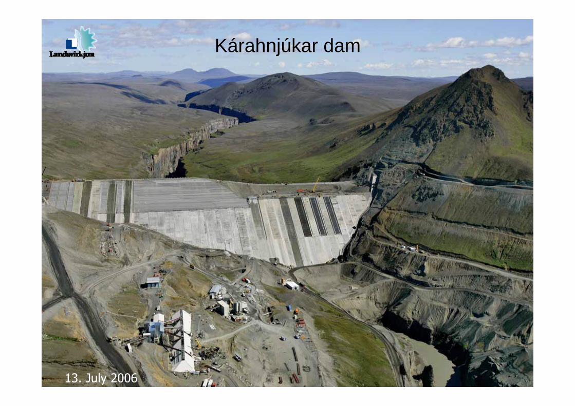
Kárahnjúkar dam
13. July 2006
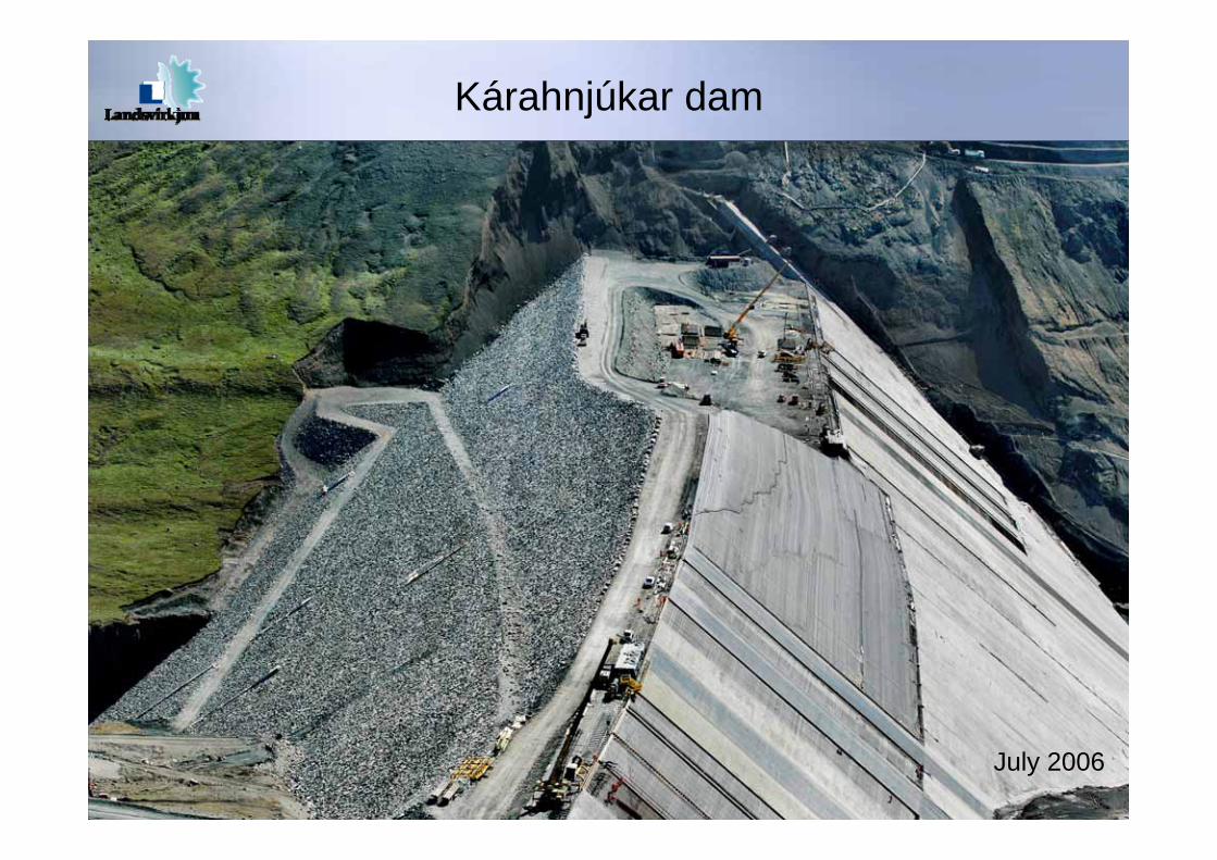
Kárahnjúkar dam
July 2006

March 28, 2007
Kárahnjúkar dam
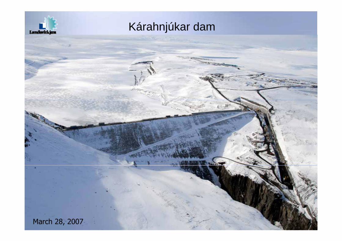
March 28, 2007
Kárahnjúkar dam
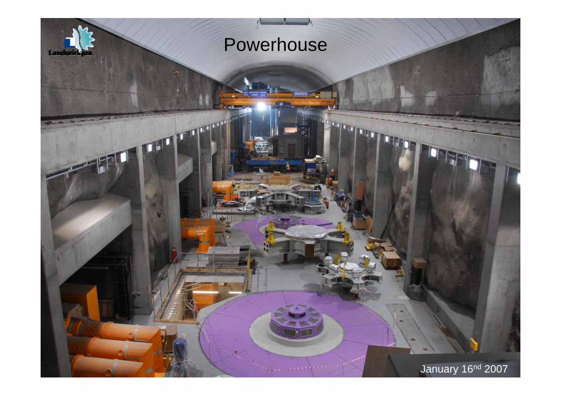
January 16nd 2007
Powerhouse
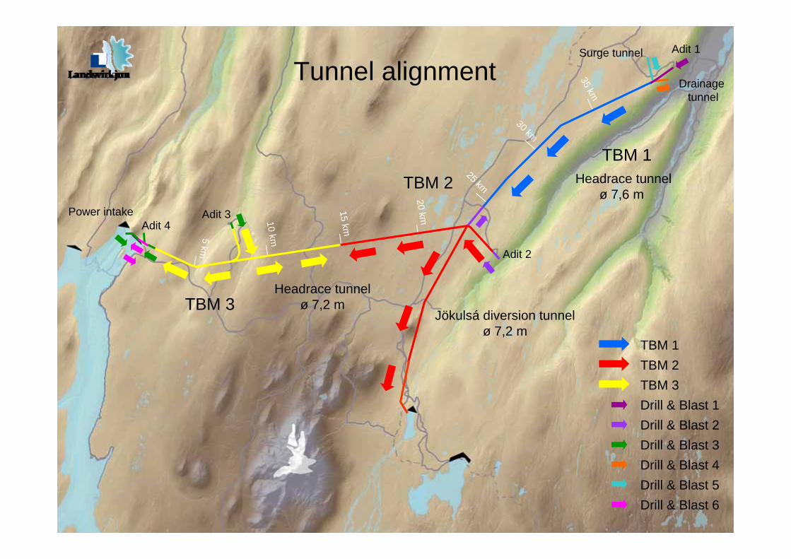
TBM 1TBM 2TBM 3Drill & Blast 1Drill & Blast 2Drill & Blast 3Drill & Blast 4Drill & Blast 5Drill & Blast 6
5 km
10 km
15 km
20 km
25 km
30 km
35 km
Adit 1
Adit 2
Adit 3Adit 4
Power intake
Surge tunnel
Drainagetunnel
Jökulsá diversion tunnelø 7,2 m
Headrace tunnelø 7,6 m
Headrace tunnelø 7,2 m
Tunnel alignment
TBM 3
TBM 2TBM 1
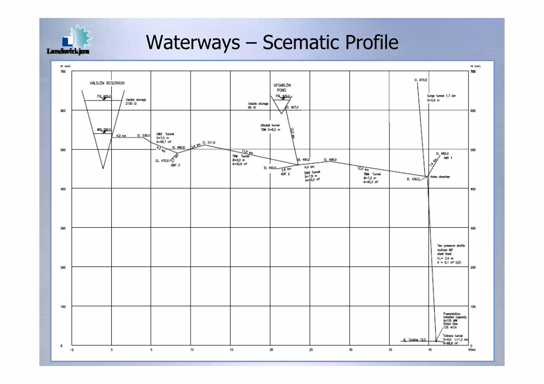
Waterways – Scematic Profile
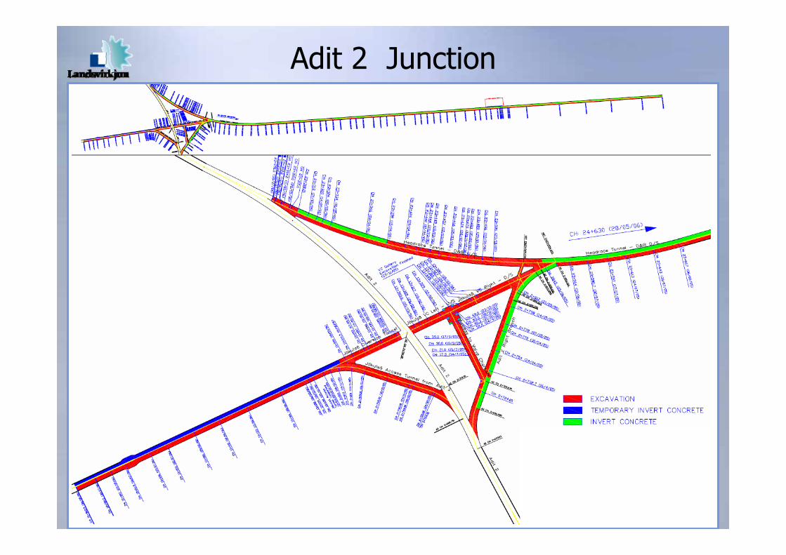
Adit 2 Junction

Design
− Geology
− Excavation classes (D&B and TBM)
− Bore classes

Geology
• Shallow dipping strata(3 to 5°)
• Basalt flows with sediments and móberg formations in between
• Móberg is volcanic rock formed in water or glacical environment
• Faults & dykes at ~200 m spacing
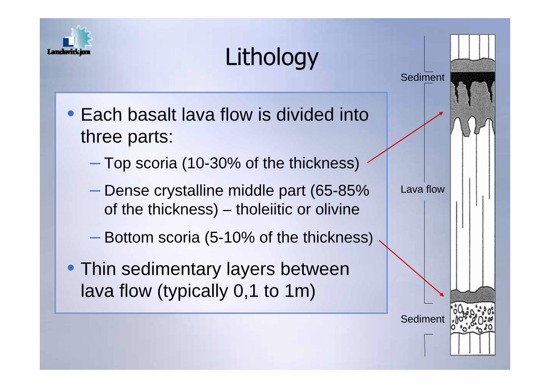
Lithology
• Each basalt lava flow is divided into three parts:– Top scoria (10-30% of the thickness)
– Dense crystalline middle part (65-85% of the thickness) – tholeiitic or olivine
– Bottom scoria (5-10% of the thickness)
• Thin sedimentary layers between lava flow (typically 0,1 to 1m)
Sediment
Lava flow
Sediment
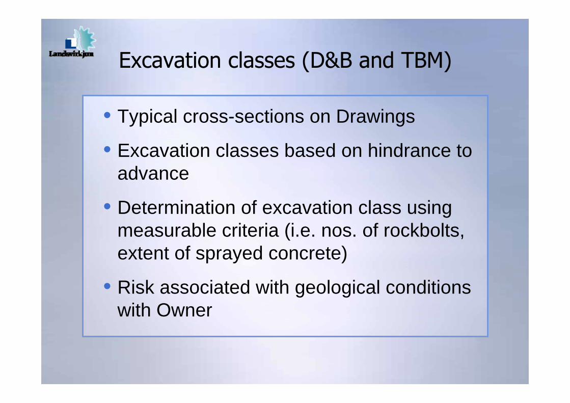
Excavation classes (D&B and TBM)
• Typical cross-sections on Drawings
• Excavation classes based on hindrance to advance
• Determination of excavation class using measurable criteria (i.e. nos. of rockbolts, extent of sprayed concrete)
• Risk associated with geological conditions with Owner
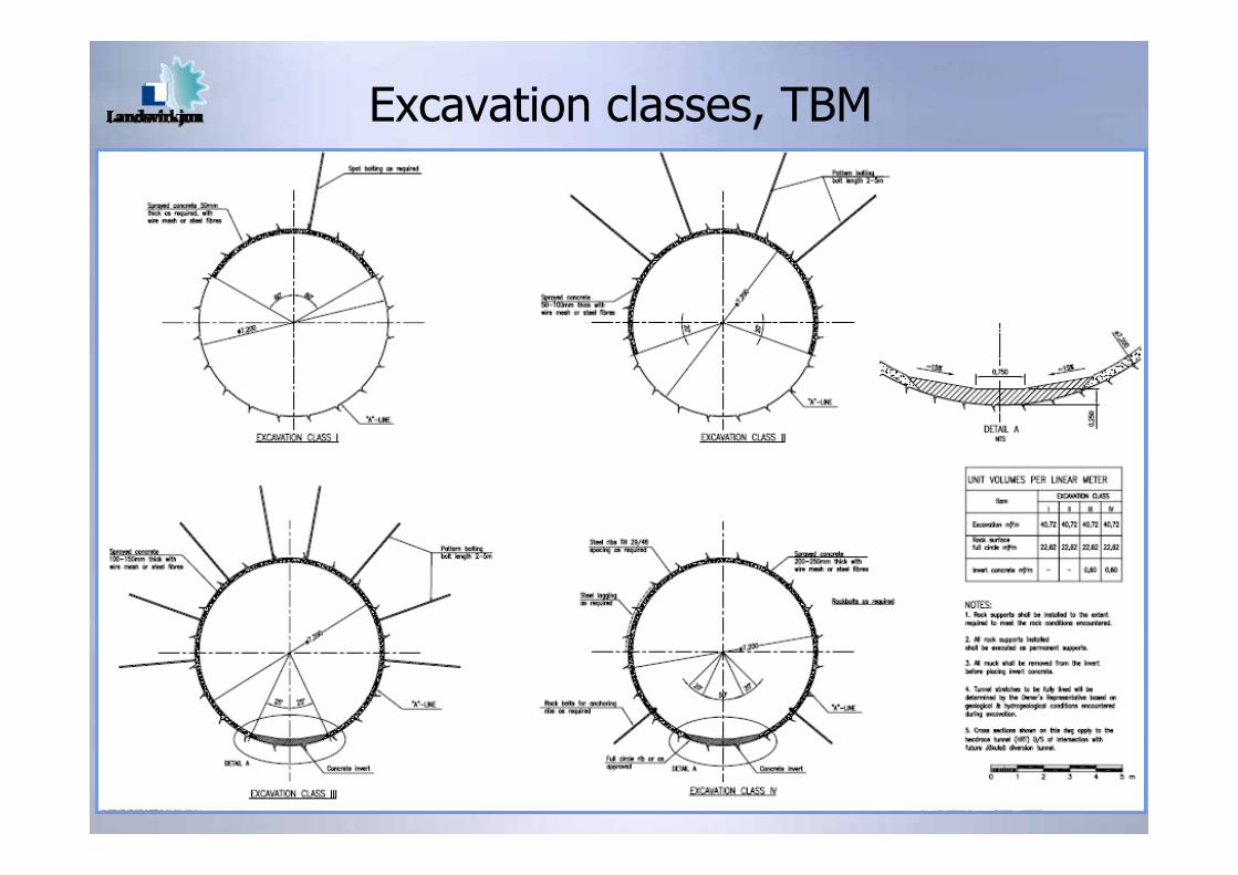
Excavation classes, TBM
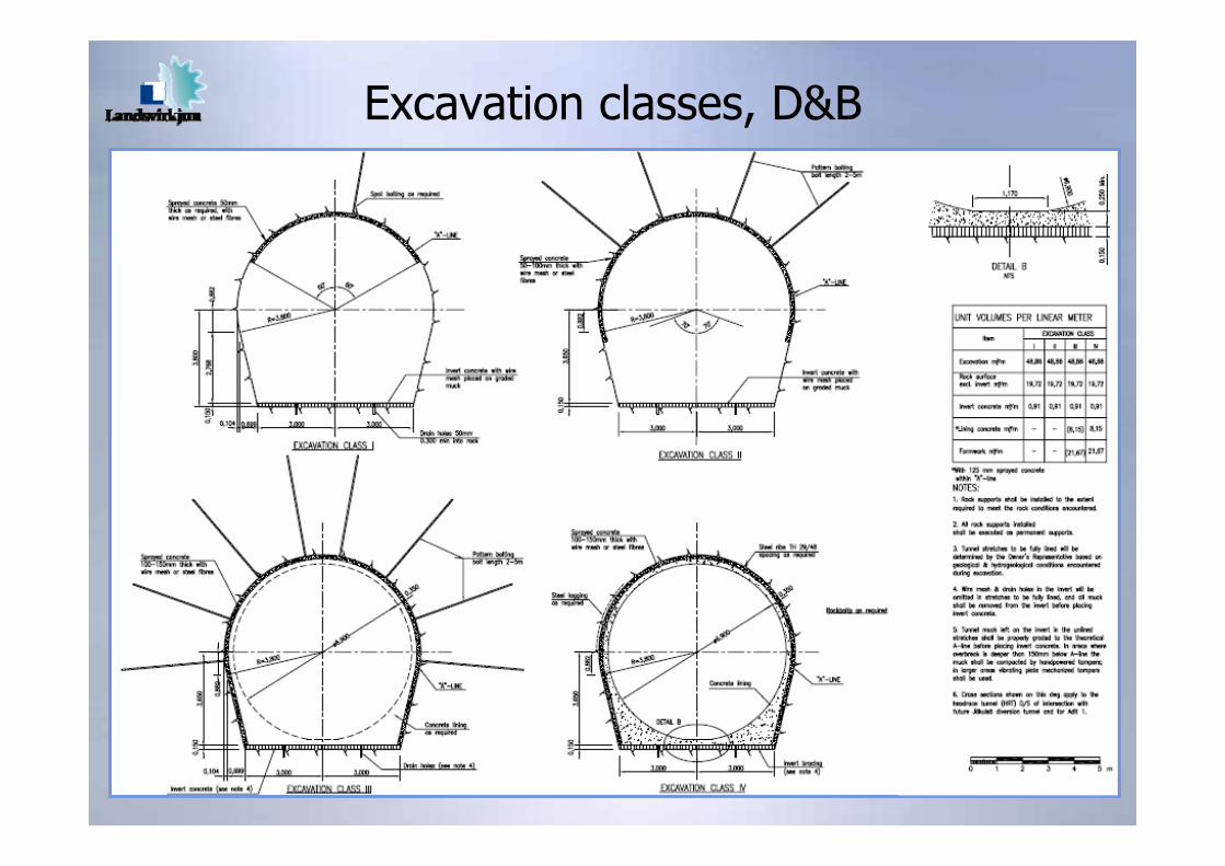
Excavation classes, D&B
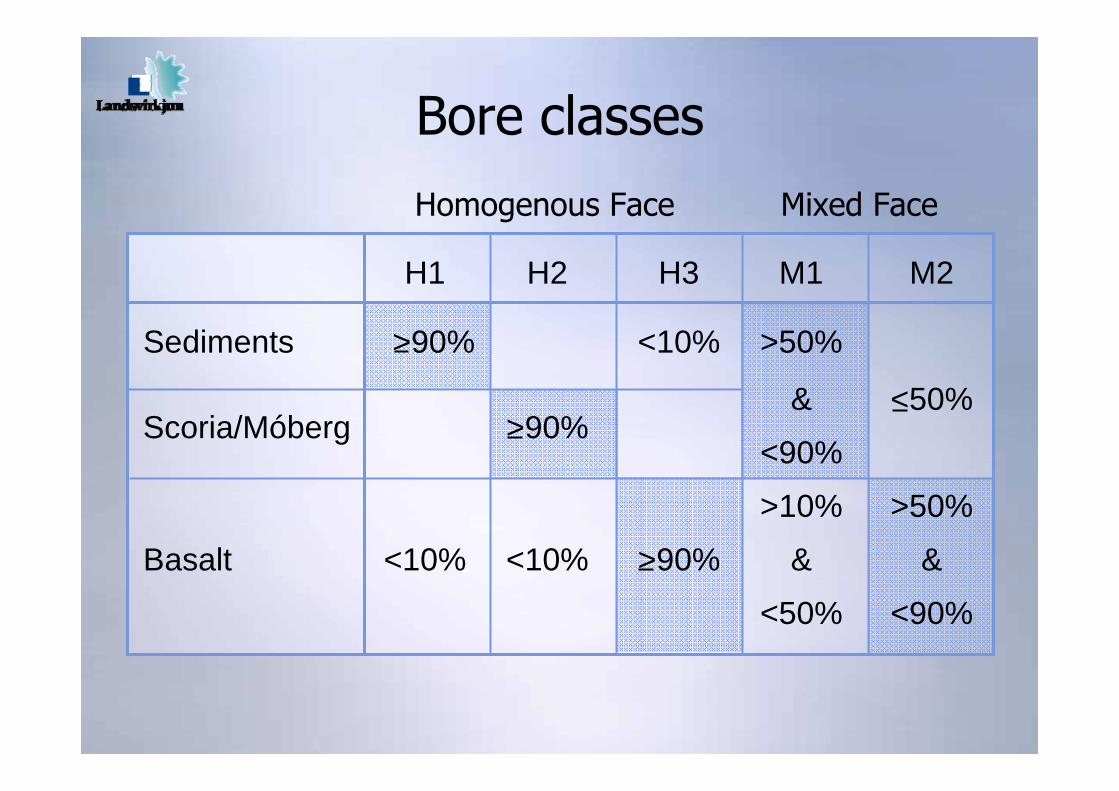
Bore classes
Scoria/Móberg >90%
H1 H2 H3 M1 M2
Sediments >90% <10% >50%
& <50%
<90%
>10% >50%
Basalt <10% <10% >90% & &
<50% <90%
Homogenous Face Mixed Face
Construction
− Robbins TBM
− Challenges encountered
− Mitigation measures
− Actual progress
− Utilization
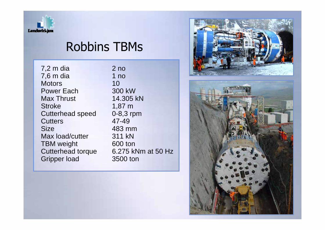
Robbins TBMs
7,2 m dia 2 no7,6 m dia 1 noMotors 10Power Each 300 kWMax Thrust 14.305 kNStroke 1,87 mCutterhead speed 0-8,3 rpmCutters 47-49Size 483 mmMax load/cutter 311 kNTBM weight 600 tonCutterhead torque 6.275 kNm at 50 HzGripper load 3500 ton

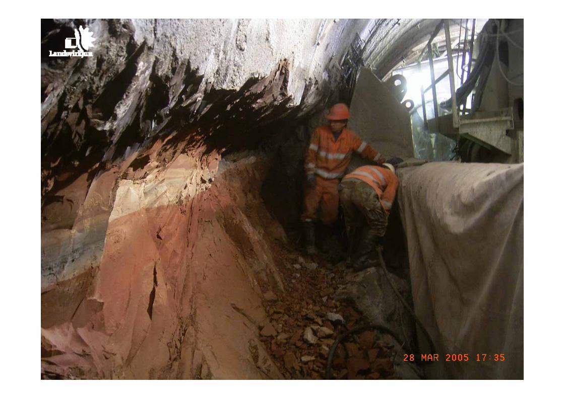
Challenges encountered
• Red sedimentary layers, HRT 1
• Fault zone, HRT 2
• High water inflow, HRT 3
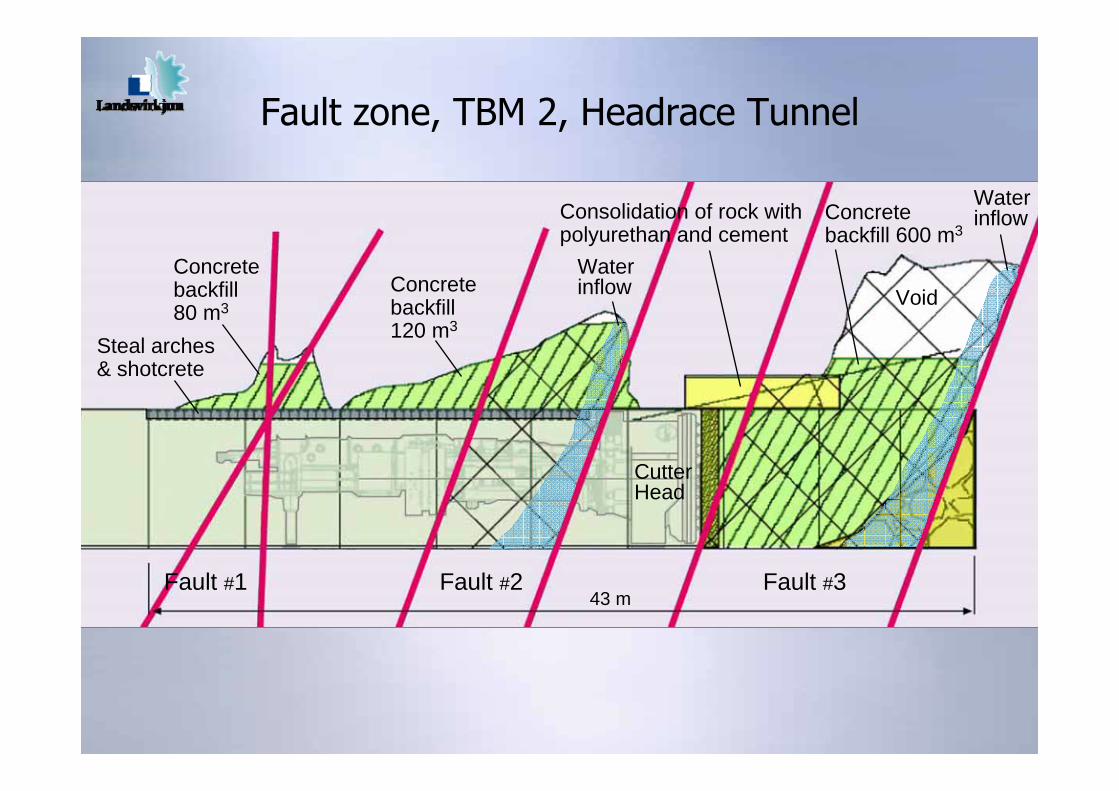
Fault zone, TBM 2, Headrace Tunnel
Fault #1 Fault #2 Fault #3
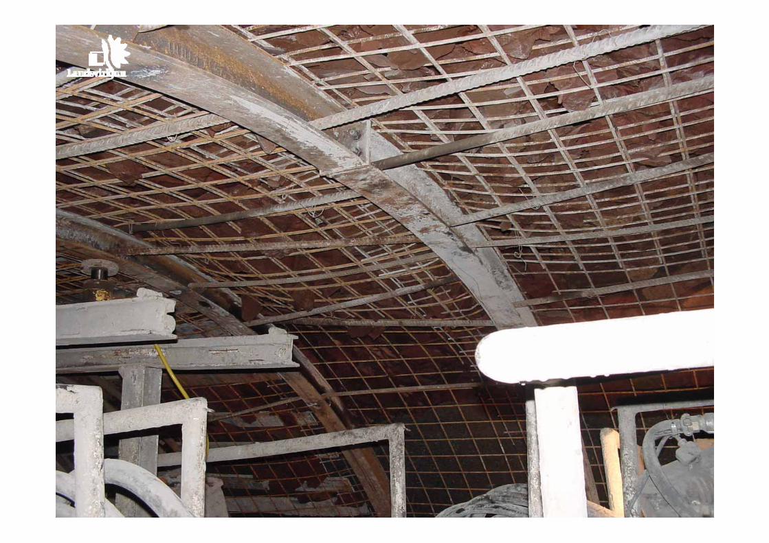
Steal arches& shotcrete
43 m
Concretebackfill80 m3
Concretebackfill120 m3
Concretebackfill 600 m3
Consolidation of rock withpolyurethan and cement
Void
CutterHead
Waterinflow
Waterinflow
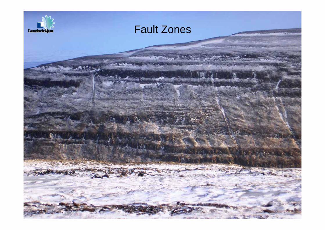
Fault Zones
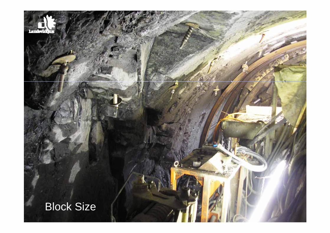
Block Size

Closely-Spaced Steel Arches
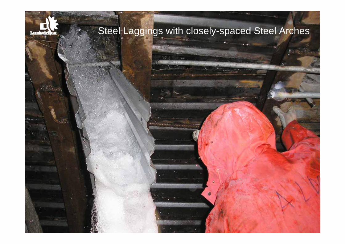
Steel Laggings with closely-spaced Steel Arches

Fault No.1 Spiling
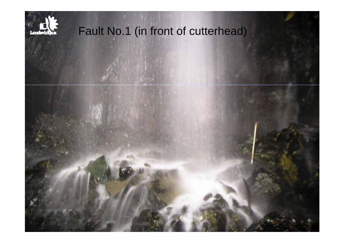
Fault No.1 (in front of cutterhead)
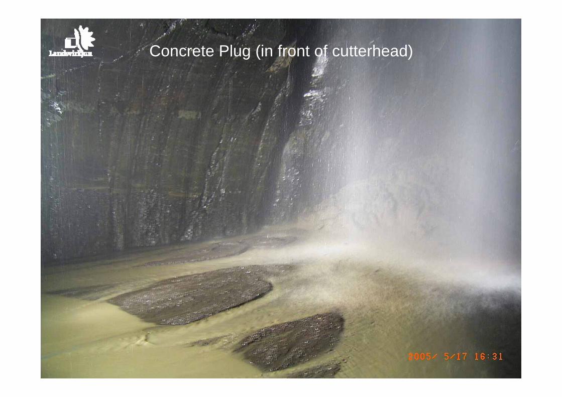
Concrete Plug (in front of cutterhead)

PU Foam
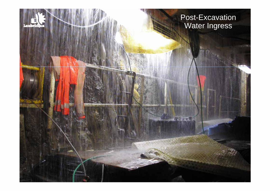
Post-ExcavationWater Ingress
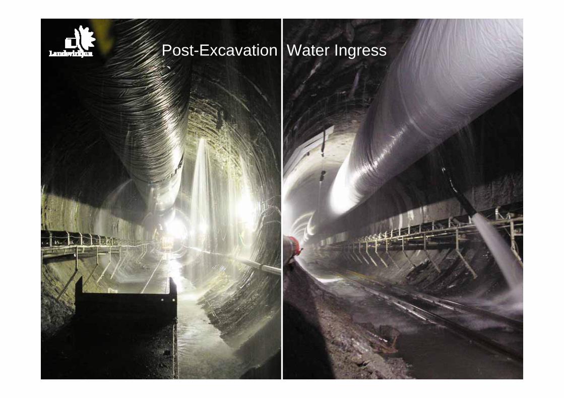
Post-Excavation Water Ingress
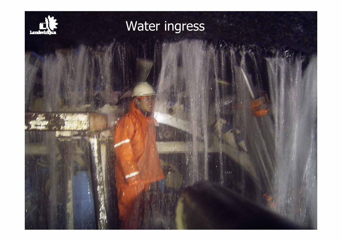
Water ingress
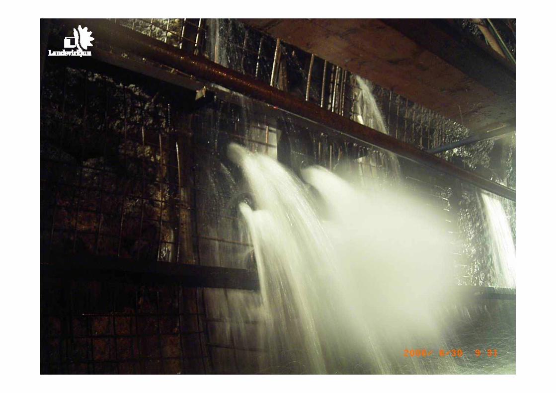
Water inflow
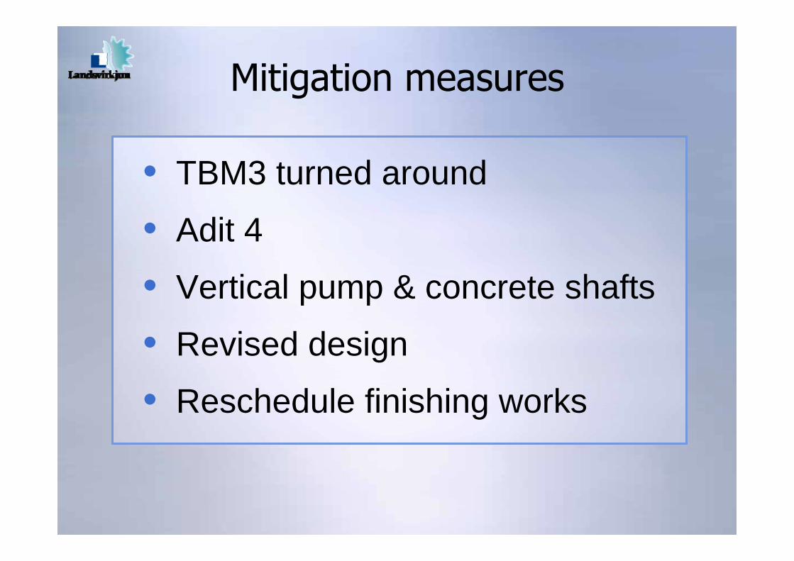
• TBM3 turned around
• Adit 4
• Vertical pump & concrete shafts
• Revised design
• Reschedule finishing works
Mitigation measures

TBM 1TBM 2TBM 3Drill & Blast 1Drill & Blast 2Drill & Blast 3Drill & Blast 4Drill & Blast 5Drill & Blast 6
5 km
10 km
15 km
20 km
25 km
30 km
35 km
Adit 1
Adit 2
Adit 3Adit 4
Power intake
Surge tunnel
Drainagetunnel
Jökulsá diversion tunnelø 7,2 m
Headrace tunnelø 7,6 m
Headrace tunnelø 7,2 m
Tunnel alignment
TBM 3
TBM 2TBM 1
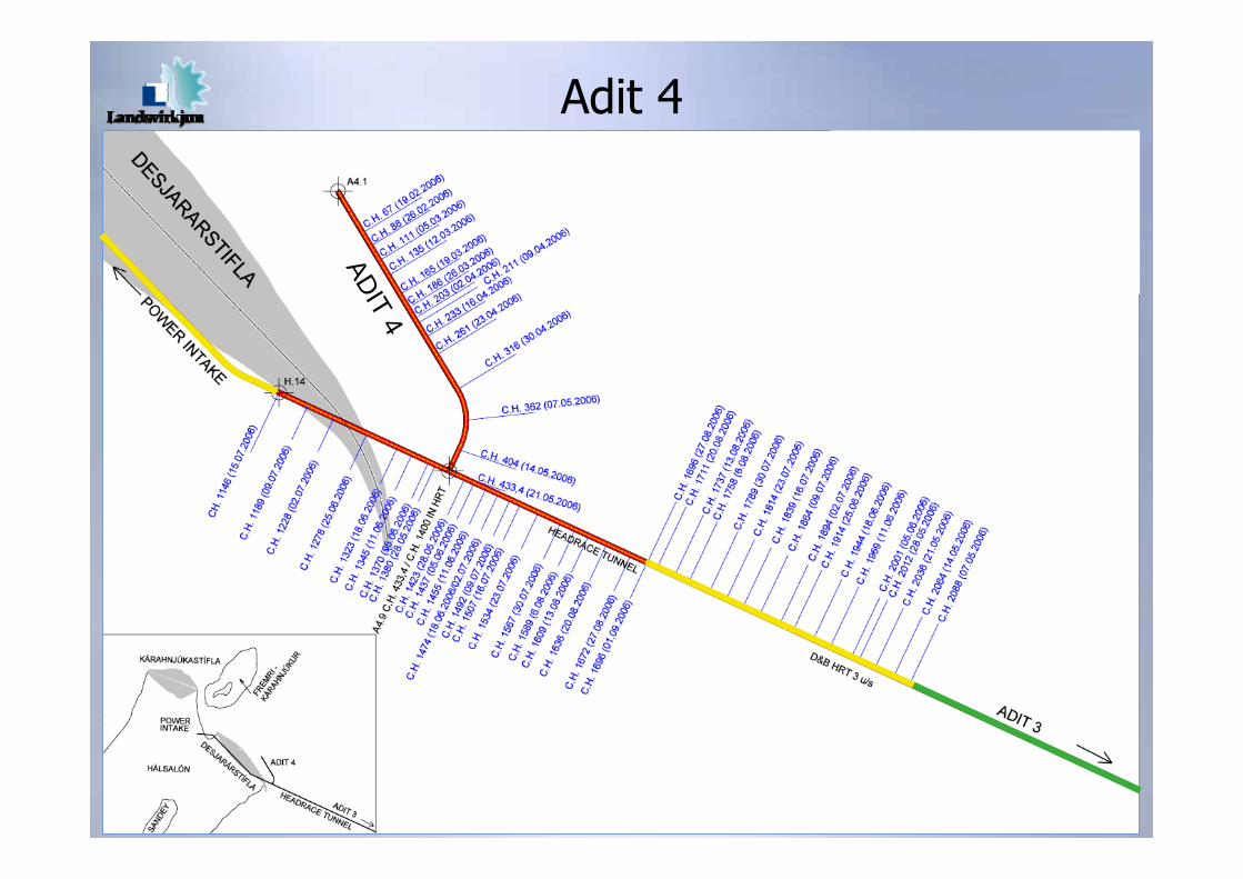
ADIT 4
Adit 4

Shaft chainage 5204 for pumps
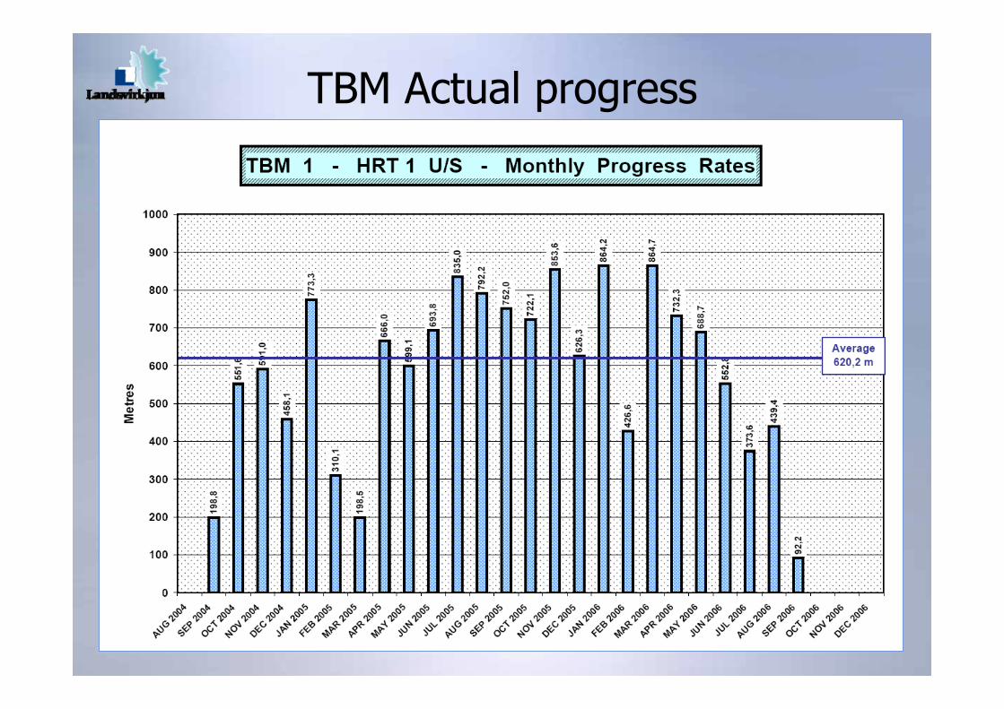
TBM Actual progress
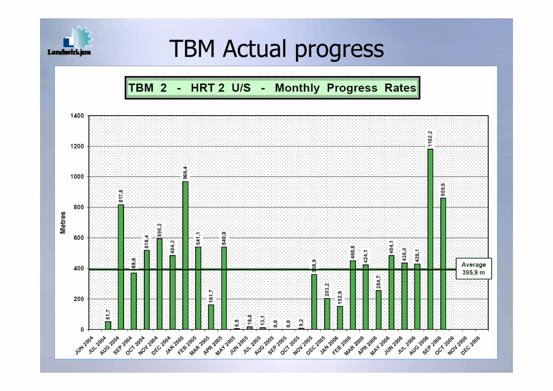
TBM Actual progress
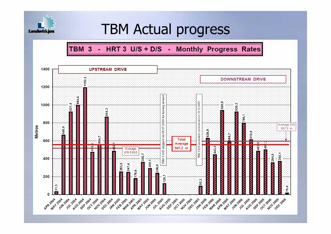
TBM Actual progress
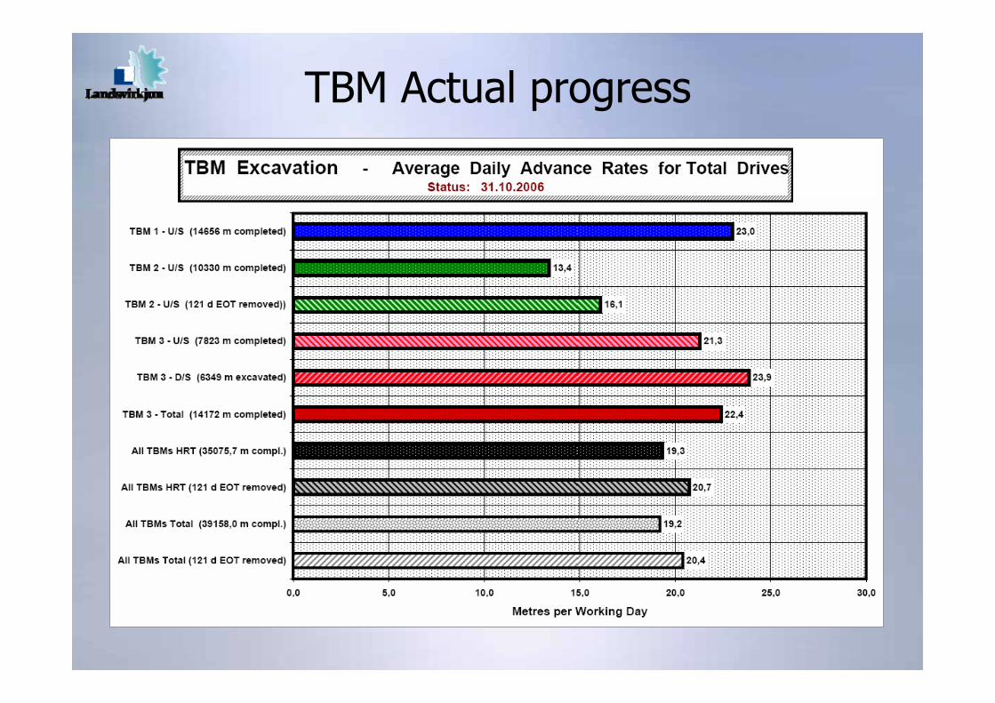
TBM Actual progress
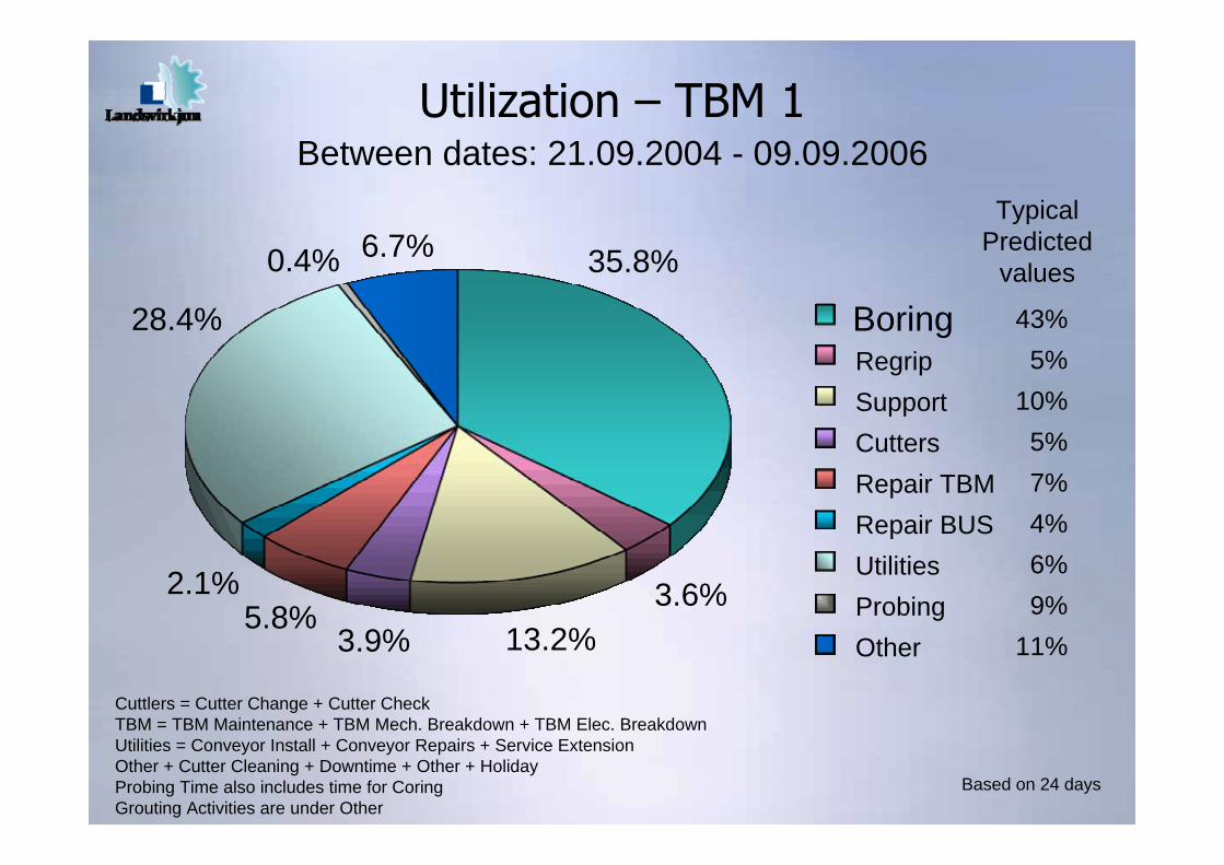
Utilization – TBM 1Between dates: 21.09.2004 - 09.09.2006
Cuttlers = Cutter Change + Cutter CheckTBM = TBM Maintenance + TBM Mech. Breakdown + TBM Elec. BreakdownUtilities = Conveyor Install + Conveyor Repairs + Service ExtensionOther + Cutter Cleaning + Downtime + Other + HolidayProbing Time also includes time for CoringGrouting Activities are under Other
Based on 24 days
BoringRegripSupportCuttersRepair TBMRepair BUSUtilitiesProbingOther
28.4%
0.4%
3.9%5.8%
2.1%
13.2%
6.7%
3.6%
35.8%
43%5%
10%5%7%4%6%9%
11%
TypicalPredicted
values
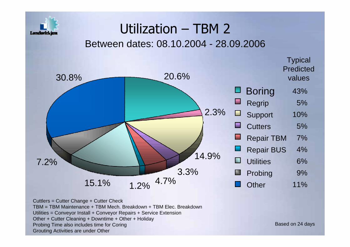
Utilization – TBM 2Between dates: 08.10.2004 - 28.09.2006
Cuttlers = Cutter Change + Cutter CheckTBM = TBM Maintenance + TBM Mech. Breakdown + TBM Elec. BreakdownUtilities = Conveyor Install + Conveyor Repairs + Service ExtensionOther + Cutter Cleaning + Downtime + Other + HolidayProbing Time also includes time for CoringGrouting Activities are under Other
Based on 24 days
BoringRegripSupportCuttersRepair TBMRepair BUSUtilitiesProbingOther
30.8%
1.2%15.1% 4.7%
7.2% 14.9%
2.3%
20.6%43%
5%10%
5%7%4%6%9%
11%
TypicalPredicted
values
3.3%
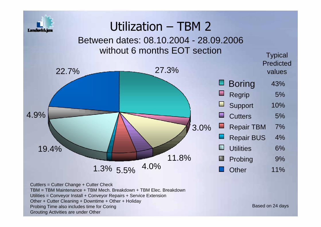
Utilization – TBM 2Between dates: 08.10.2004 - 28.09.2006
without 6 months EOT section
Cuttlers = Cutter Change + Cutter CheckTBM = TBM Maintenance + TBM Mech. Breakdown + TBM Elec. BreakdownUtilities = Conveyor Install + Conveyor Repairs + Service ExtensionOther + Cutter Cleaning + Downtime + Other + HolidayProbing Time also includes time for CoringGrouting Activities are under Other
Based on 24 days
BoringRegripSupportCuttersRepair TBMRepair BUSUtilitiesProbingOther
22.7%
5.5%1.3% 4.0%
19.4%
3.0%4.9%
27.3%43%
5%10%
5%7%4%6%9%
11%
TypicalPredicted
values
11.8%
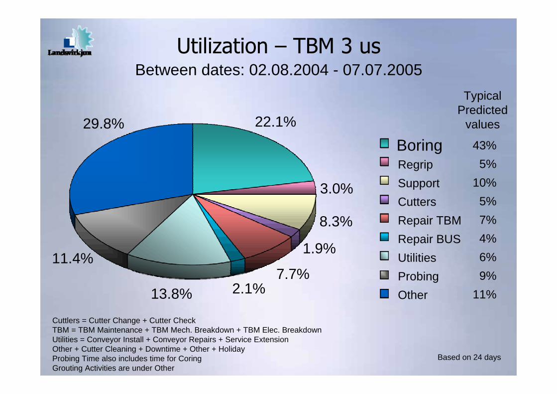
Utilization – TBM 3 usBetween dates: 02.08.2004 - 07.07.2005
Cuttlers = Cutter Change + Cutter CheckTBM = TBM Maintenance + TBM Mech. Breakdown + TBM Elec. BreakdownUtilities = Conveyor Install + Conveyor Repairs + Service ExtensionOther + Cutter Cleaning + Downtime + Other + HolidayProbing Time also includes time for CoringGrouting Activities are under Other
Based on 24 days
BoringRegripSupportCuttersRepair TBMRepair BUSUtilitiesProbingOther
29.8%
8.3%
13.8% 2.1%
11.4%
3.0%
1.9%
22.1%43%
5%10%
5%7%4%6%9%
11%
TypicalPredicted
values
7.7%
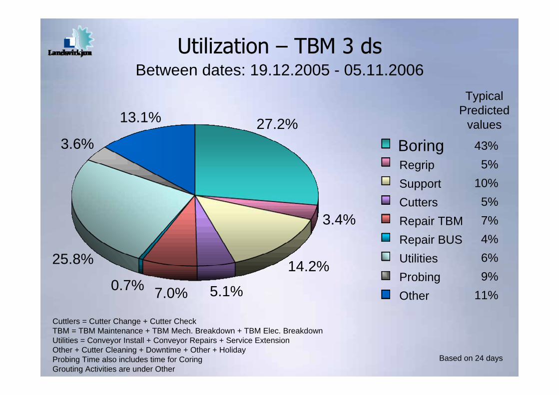
Utilization – TBM 3 dsBetween dates: 19.12.2005 - 05.11.2006
Cuttlers = Cutter Change + Cutter CheckTBM = TBM Maintenance + TBM Mech. Breakdown + TBM Elec. BreakdownUtilities = Conveyor Install + Conveyor Repairs + Service ExtensionOther + Cutter Cleaning + Downtime + Other + HolidayProbing Time also includes time for CoringGrouting Activities are under Other
Based on 24 days
BoringRegripSupportCuttersRepair TBMRepair BUSUtilitiesProbingOther
13.1%
7.0%0.7% 5.1%
25.8%
3.4%
14.2%
27.2%43%
5%10%
5%7%4%6%9%
11%
TypicalPredicted
values
3.6%
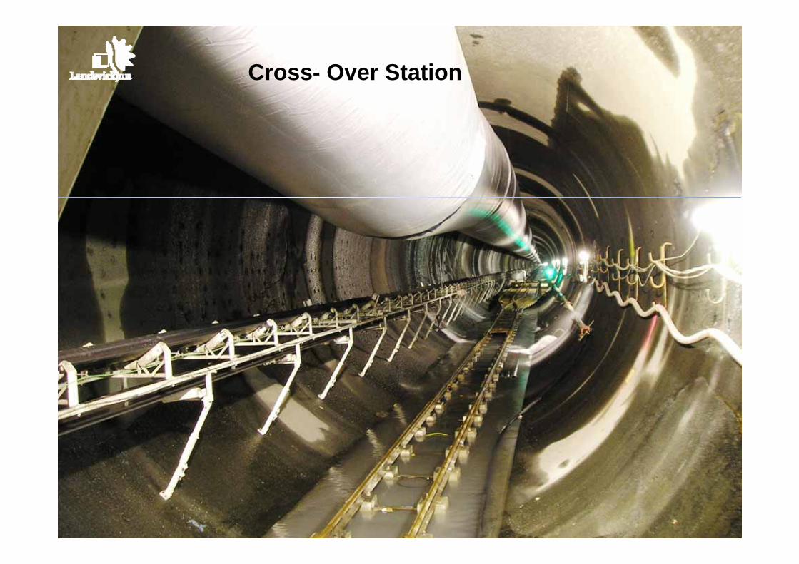
Cross- Over Station
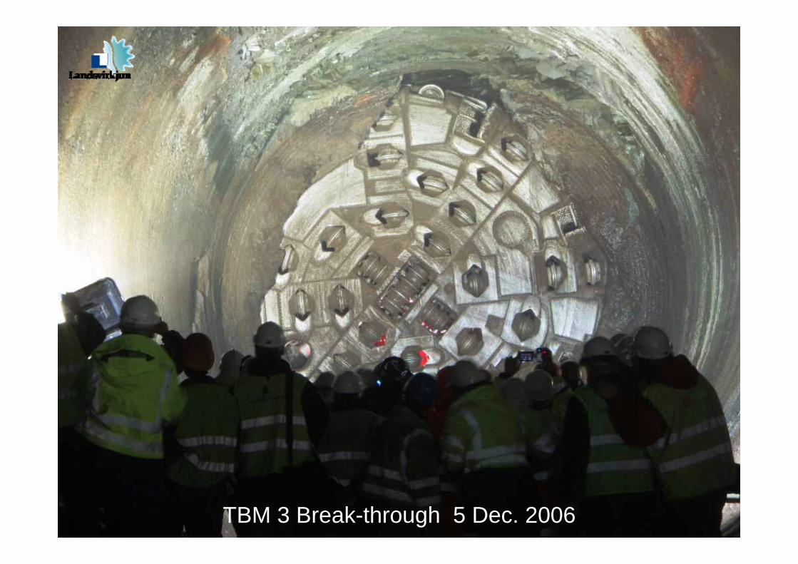
TBM 3 Break-through 5 Dec. 2006
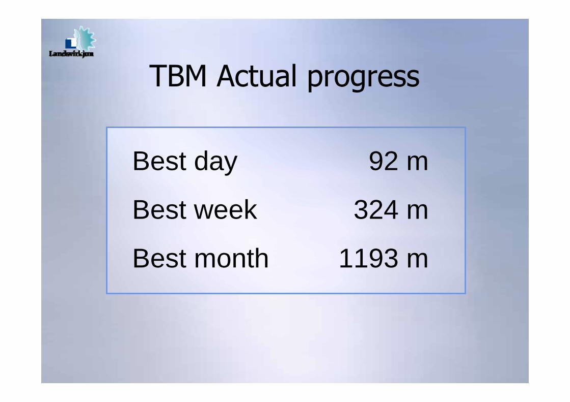
Best day 92 m
Best week 324 m
Best month 1193 m
TBM Actual progress
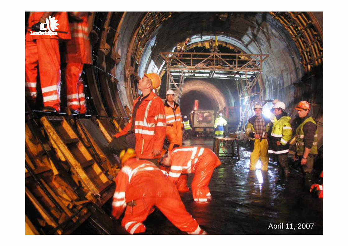
April 11, 2007
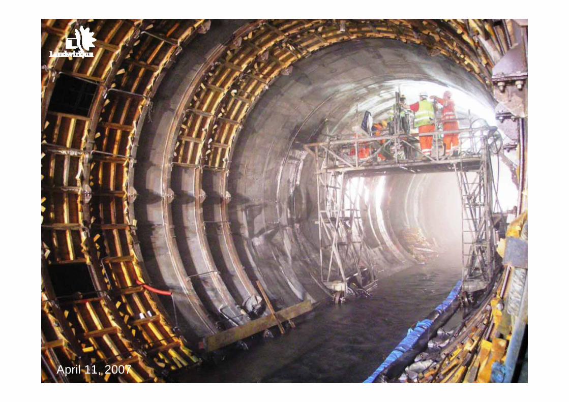
April 11, 2007

Conclusions− First use of TBMs in Iceland− TBMs are generally well suited for
Icelandic mixed faced basaltic rock− Challenging ground
−Mixed face− Fault zones−Water ingress
− Conveyors can be effective for long, large diameter tunnel drives
March 28, 2007March 28, 2007
Thank you for your attention!