Catálogos Levante Sistemas de Automatización y Control S.L....Levante Sistemas de Automatización...
143
Levante Sistemas de Automatización y Control S.L. Catálogos www.lsa-control.com Distribuidor oficial Bosch Rexroth, Indramat, Bosch y Aventics. LSA Control S.L. - Bosch Rexroth Sales Partner Ronda Narciso Monturiol y Estarriol, 7-9 Edificio TecnoParQ Planta 1ª Derecha, Oficina 14 (Parque Tecnológico de Paterna) 46980 Paterna (Valencia) Telf. (+34) 960 62 43 01 [email protected] www.lsa-control.com www.boschrexroth.es
Transcript of Catálogos Levante Sistemas de Automatización y Control S.L....Levante Sistemas de Automatización...
Levante Sistemas de Automatización y Control S.L.
Catálogos
www.lsa-control.com
Distribuidor oficial Bosch Rexroth, Indramat, Bosch y Aventics.
LSA Control S.L. - Bosch Rexroth Sales PartnerRonda Narciso Monturiol y Estarriol, 7-9Edificio TecnoParQ Planta 1ª Derecha, Oficina 14(Parque Tecnológico de Paterna)46980 Paterna (Valencia)Telf. (+34) 960 62 43 01 [email protected] www.lsa-control.com www.boschrexroth.es
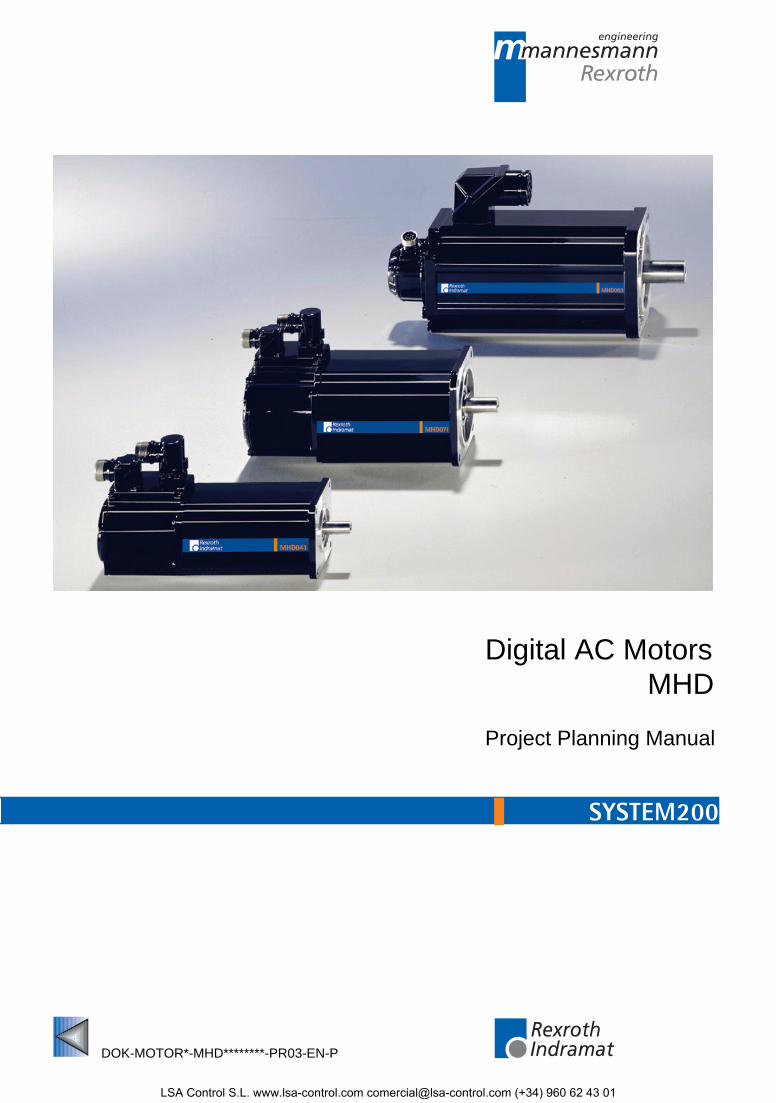
Digital AC MotorsMHD
Project Planning Manual
DOK-MOTOR*-MHD********-PR03-EN-P
mannesmannRexroth
engineering
IndramatRexroth
7=78)1���
LSA Control S.L. www.lsa-control.com [email protected] (+34) 960 62 43 01
About this Documentation Digital AC- Motors MHD
DOK-MOTOR*-MHD********-PR03-EN-P
Digital AC Motors
Project Planning Manual
DOK-MOTOR*-MHD********-PR03-EN-P
• drawing number: 120-1500-B307-03/EN
This document helps
• in the familiarization with digital MHD AC motors
• to plan the mechanical integration into the installation
• to plan the electrical connections
• to connect the motor
• to order or identify a motor
• to determine the required motor cable and connector
Document identification of previousand present output
ReleaseDate
Comments
DOK-MOTOR*-MHD********-PRJ1-EN-P 10.96 1st edition
DOK-MOTOR*-MHD********-PRJ2-EN-P 11.98 Newly includedMHD041A,MHD071A, MHD090,MHD112, correctionof technical data
DOK-MOTOR*-MHD********-PR03-EN-P 09.99 Revision
REXROTH INDRAMAT GmbH, 1999
Transmission as well as reproduction of this documentation, commercialuse or communication of its contents will not be permitted withoutexpressed written permission. Violation of these stipulations will requirecompensation. All rights reserved for the issuance of the patent orregistered design. (DIN 34-1)
All rights are reserved with respect to the content of this documentationand the availability of the product.
REXROTH INDRAMAT GmbHBgm.-Dr.-Nebel-Str. 2 • D-97816 Lohr a. Main
Telephone 09352/40-0 • Tx 689421 • Fax 09352/40-4885
http://www.rexroth.com/indramat
Dept. ECM5(JW)
This document has been printed on chlorine-free bleached paper.
Title
Type of documentation
Documentation code
Internal file reference
What is the purpose of thisdocument?
Course of modifications
Copyright
Validity
Published by
Note
LSA Control S.L. www.lsa-control.com [email protected] (+34) 960 62 43 01
Digital AC- Motors MHD Contents I
DOK-MOTOR*-MHD********-PR03-EN-P
Contents
1 Introducing MHD AC Motors............................................................................... 1-1
1.1 General Features ............................................................................................................................... 1-1
1.2 Designs .............................................................................................................................................. 1-3
1.3 Motor Feedback ................................................................................................................................. 1-4
2 Safety Instructions for Electrical Drives............................................................ 2-1
2.1 Introduction......................................................................................................................................... 2-1
2.2 Hazards by improper use ................................................................................................................... 2-2
2.3 General............................................................................................................................................... 2-3
2.4 Protection against contact with electrical parts and not grounded enclosures .................................. 2-4
2.5 Protection by protective low voltage (PELV) against electrical shock .......................................... 2-5
2.6 Protection against dangerous movements......................................................................................... 2-6
2.7 Protection against magnetic and electromagnetic fields during operations and mounting................ 2-7
2.8 Protection against contact with hot parts ........................................................................................... 2-8
2.9 Protection during handling and installation ........................................................................................ 2-8
2.10 Battery safety.................................................................................................................................... 2-9
3 Integrating Mechanically into the Installation ................................................... 3-1
3.1 Installation Elevation and Ambient Temperature ............................................................................... 3-1
3.2 Protection Category............................................................................................................................ 3-2
Selecting the Protection Category...................................................................................................... 3-4
Selection List for Sealing Air Connection Accessories ...................................................................... 3-5
3.3 Form and Mounting Position .............................................................................................................. 3-6
3.4 Prime Coat and Housing Finish ......................................................................................................... 3-6
3.5 Maximum Vibrations and Shock demands......................................................................................... 3-6
3.6 Output Shafts ..................................................................................................................................... 3-7
Available types ................................................................................................................................... 3-7
Shaft load ........................................................................................................................................... 3-8
3.7 Surface Cooling................................................................................................................................ 3-10
3.8 Liquid-Cooled MHD Motors.............................................................................................................. 3-11
3.9 Holding Brake................................................................................................................................... 3-11
3.10 Output Direction of the Electrical Connections............................................................................... 3-13
3.11 Speed/Torque Characteristics ........................................................................................................ 3-14
4 Electrical Connections........................................................................................ 4-1
4.1 An Overview of the Connections........................................................................................................ 4-1
4.2 Power Cables ..................................................................................................................................... 4-2
4.3 Feedback Cables ............................................................................................................................. 4-12
LSA Control S.L. www.lsa-control.com [email protected] (+34) 960 62 43 01
II Contents Digital AC- Motors MHD
DOK-MOTOR*-MHD********-PR03-EN-P
4.4 Technical Data of Power and Feedback Cables.............................................................................. 4-13
4.5 Individual Parts................................................................................................................................. 4-14
5 Connections for Liquid-Cooling......................................................................... 5-1
5.1 Types of Connections......................................................................................................................... 5-1
5.2 Connection Instructions...................................................................................................................... 5-1
6 MHD041 ................................................................................................................ 6-1
6.1 Technical Data ................................................................................................................................... 6-1
6.2 Speed/Torque Characteristics............................................................................................................ 6-2
6.3 Data for Determining Maximum Shaft Load....................................................................................... 6-4
6.4 Dimensional Data ............................................................................................................................... 6-5
6.5 Available Versions and Type Codes .................................................................................................. 6-6
7 MHD071 ................................................................................................................ 7-1
7.1 Technical Data ................................................................................................................................... 7-1
7.2 Speed/Torque Characteristics............................................................................................................ 7-2
7.3 Data for Determining Maximum Shaft Load....................................................................................... 7-4
7.4 Dimensional Data ............................................................................................................................... 7-5
7.5 Available Versions and Type Codes .................................................................................................. 7-6
7.6 Surface cooling................................................................................................................................... 7-7
8 MHD090 ................................................................................................................ 8-1
8.1 Technical Data ................................................................................................................................... 8-1
8.2 Speed/Torque Characteristics............................................................................................................ 8-2
8.3 Data for Determining Shaft Capacity.................................................................................................. 8-4
8.4 Dimensional Data ............................................................................................................................... 8-5
8.5 Available Versions and Type Codes .................................................................................................. 8-6
8.6 Surface cooling................................................................................................................................... 8-7
9 MHD093 ................................................................................................................ 9-1
9.1 Technical Data ................................................................................................................................... 9-1
9.2 Speed/Torque Characteristics............................................................................................................ 9-3
9.3 Data on Determining Maximum Shaft Load ....................................................................................... 9-7
9.4 Dimensional Data (Standard cooling) ................................................................................................ 9-8
9.5 Dimensional Data (Liquid cooling) ..................................................................................................... 9-9
9.6 Available Versions and Type Codes ................................................................................................ 9-10
9.7 Surface cooling................................................................................................................................. 9-11
10 MHD112 .............................................................................................................. 10-1
10.1 Technical Data................................................................................................................................ 10-1
10.2 Speed/Torque Characteristics ........................................................................................................ 10-5
10.3 Data on Determining Maximum Shaft Load ................................................................................... 10-9
10.4 Dimensional Data ......................................................................................................................... 10-10
10.5 Available Versions and Type Codes ............................................................................................ 10-12
10.6 Surface cooling ............................................................................................................................. 10-13
LSA Control S.L. www.lsa-control.com [email protected] (+34) 960 62 43 01
Digital AC- Motors MHD Contents III
DOK-MOTOR*-MHD********-PR03-EN-P
11 MHD115 .............................................................................................................. 11-1
11.1 Technical Data................................................................................................................................ 11-1
11.2 Speed/Torque Characteristics ........................................................................................................ 11-3
11.3 Data for Determining Maximum Shaft Load ................................................................................... 11-6
11.4 Dimensional Data ........................................................................................................................... 11-7
11.5 Available Versions and Type Codes .............................................................................................. 11-9
11.6 Surface cooling ............................................................................................................................. 11-10
12 State at Delivery................................................................................................. 12-1
12.1 General Information........................................................................................................................ 12-1
12.2 Releasing the Taut Bands .............................................................................................................. 12-1
12.3 Documentation................................................................................................................................ 12-1
13 Identifying the Merchandise ............................................................................. 13-1
13.1 Delivery Slip.................................................................................................................................... 13-1
13.2 Barcode Sticker .............................................................................................................................. 13-1
13.3 Type Plates..................................................................................................................................... 13-1
14 Storage, Transport and Handling..................................................................... 14-1
14.1 Notes on Packaging ....................................................................................................................... 14-1
14.2 Storage ........................................................................................................................................... 14-1
14.3 Transport and Handling .................................................................................................................. 14-2
15 Mounting and Installation ................................................................................. 15-1
15.1 General Information on Mounting ................................................................................................... 15-1
15.2 Mounting the Motor......................................................................................................................... 15-1
15.3 Connecting the Motor ..................................................................................................................... 15-1
Connecting Ready-Made Cables ..................................................................................................... 15-3
Changing the Output Direction of Power and Feedback Connectors .............................................. 15-4
15.4 Connecting and Mounting the Blower Connector........................................................................... 15-7
15.5 Cleaning the Holding Brakes.......................................................................................................... 15-8
16 Service Guidelines ............................................................................................ 16-1
16.1 Maintenance ................................................................................................................................... 16-1
16.2 Contacting Customer Service......................................................................................................... 16-1
16.3 Fault Report .................................................................................................................................... 16-1
17 Index ................................................................................................................... 17-1
18 Kundenbetreuungsstellen - Sales & Service Facilities .................................. 18-1
LSA Control S.L. www.lsa-control.com [email protected] (+34) 960 62 43 01
IV Contents Digital AC- Motors MHD
DOK-MOTOR*-MHD********-PR03-EN-P
LSA Control S.L. www.lsa-control.com [email protected] (+34) 960 62 43 01
Digital AC- Motors MHD Introducing MHD AC Motors 1-1
DOK-MOTOR*-MHD********-PR03-EN-P
1 Introducing MHD AC Motors
1.1 General Features
MHD digital AC motors in conjunction with digital intelligent drivecontrollers from INDRAMAT create cost-effective automation systemsthat make available an extensive range of functionalities for such areasas
• machine tools
• transfer machines
• handling systems
• printing machines
• packaging machines and
• textile machines
The following advantages distinguish MHD motors:
• High operating reliability
• Maintenance-free operation (due to the brushless design and bearingslubricated for their entire service life)
• Can be used even under adverse environmental conditions (due tothe completely sealed motor design with a protection category of IP65)
• Overload protection (due to motor temperature monitoring)
• High power data
• High dynamics (due to favorable torque/inertia ratio)
• High overload capabilities (due to favorable heat conduction awayfrom the stator windings to the outside wall of the motor housing)
• Peak torque can be used over a broad speed range (due to electroniccommutation)
• Continuous start-stop operations with high repetitive frequencies arepossible (electronic commutation)
• Mounting into the machine is easy (due to the flange that meets therequirements as specified in DIN 42948)
• Any mounting orientation is possible
• Direct attachment of pinions and belt pulleys to the shaft as the designmakes it possible to apply high radial loads
• Simple cable routing (due to ready-made cables which are available ina variety of versions)
• Simple and quick commissioning (due to data memory in the motorfeedback)
Application range
Advantages
LSA Control S.L. www.lsa-control.com [email protected] (+34) 960 62 43 01
1-2 Introducing MHD AC Motors Digital AC- Motors MHD
DOK-MOTOR*-MHD********-PR03-EN-P
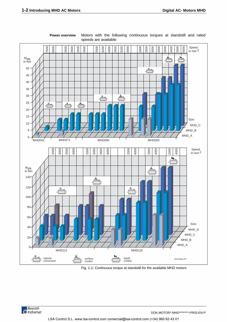
Motors with the following continuous torques at standstill and ratedspeeds are available:
naturalconvection
surfacecooled
liquidcooled
0
5
10
15
20
25
30
35
40
45
50
MHD_A
MHD_B
MHD_C
Speed in min-1
MdNin Nm
MHD041 MHD071 MHD090 MHD093
0
7500
6000
2500
4500
2500
4500
2500
3200
4000
2500
3200
4000
2000
2500
3000
4000
2500
4000
2500
4000
MHD_A
MHD_B
MHD_D
20
40
60
80
100
120
140
MHD_C
MdN in Nm
MHD112 MHD115
Speed in min-120
00
3000
3500
4000
2000
3000
3500
4000
2000
4000
2000
4000
2000
4000
Size
Size
o01mh81p.fh7
Fig. 1-1: Continuous torque at standstill for the available MHD motors
Power overview
LSA Control S.L. www.lsa-control.com [email protected] (+34) 960 62 43 01
Digital AC- Motors MHD Introducing MHD AC Motors 1-3
DOK-MOTOR*-MHD********-PR03-EN-P
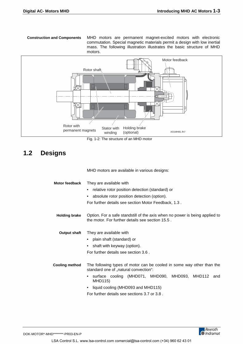
MHD motors are permanent magnet-excited motors with electroniccommutation. Special magnetic materials permit a design with low inertialmass. The following illustration illustrates the basic structure of MHDmotors.
X01MH81.fh7
Rotor shaft
Motor feedback
Rotor withpermanent magnets
Holding brake(optional)
Stator withwinding
Fig. 1-2: The structure of an MHD motor
1.2 Designs
MHD motors are available in various designs:
They are available with
• relative rotor position detection (standard) or
• absolute rotor position detection (option).
For further details see section Motor Feedback, 1.3 .
Option. For a safe standstill of the axis when no power is being applied tothe motor. For further details see section 15.5 .
They are available with
• plain shaft (standard) or
• shaft with keyway (option).
For further details see section 3.6 .
The following types of motor can be cooled in some way other than thestandard one of „natural convection“:
• surface cooling (MHD071, MHD090, MHD093, MHD112 andMHD115)
• liquid cooling (MHD093 and MHD115)
For further details see sections 3.7 or 3.8 .
Construction and Components
Motor feedback
Holding brake
Output shaft
Cooling method
LSA Control S.L. www.lsa-control.com [email protected] (+34) 960 62 43 01
1-4 Introducing MHD AC Motors Digital AC- Motors MHD
DOK-MOTOR*-MHD********-PR03-EN-P
1.3 Motor Feedback
The drive controller needs the current motor position to control motorspeed and to position.
The integrated motor feedback supplies the drive controller with theappropriate signals. Controllers are generally able to transmit thedetermined position value to a higher-ranking CNC or PLC.
The feedback electronics are equipped with data memory in which motortype designations, control loop and motor parameters are stored.
INDRAMAT’s digital intelligent drive controllers can read this data. Thisensures a
• rapid and simple start-up
• and adjustments between motor and drive controllers without thedanger of damage to the motor.
MHD motors are available with two position evaluation types
• relative position detection or
• absolute position detection.
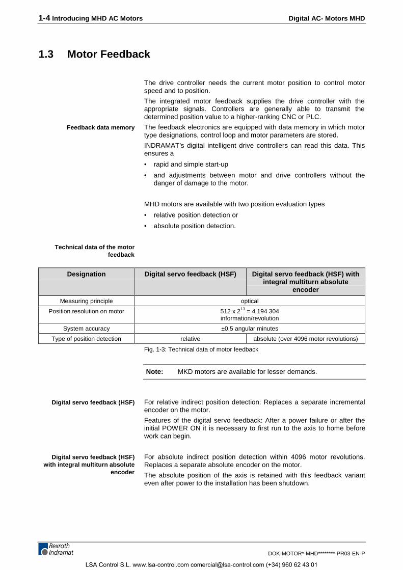
Designation Digital servo feedback (HSF) Digital servo feedback (HSF) withintegral multiturn absolute
encoder
Measuring principle optical
Position resolution on motor 512 x 213 = 4 194 304information/revolution
System accuracy ±0.5 angular minutes
Type of position detection relative absolute (over 4096 motor revolutions)
Fig. 1-3: Technical data of motor feedback
Note: MKD motors are available for lesser demands.
For relative indirect position detection: Replaces a separate incrementalencoder on the motor.
Features of the digital servo feedback: After a power failure or after theinitial POWER ON it is necessary to first run to the axis to home beforework can begin.
For absolute indirect position detection within 4096 motor revolutions.Replaces a separate absolute encoder on the motor.
The absolute position of the axis is retained with this feedback varianteven after power to the installation has been shutdown.
Feedback data memory
Technical data of the motorfeedback
Digital servo feedback (HSF)
Digital servo feedback (HSF)with integral multiturn absolute
encoder
LSA Control S.L. www.lsa-control.com [email protected] (+34) 960 62 43 01
Digital AC- Motors MHD Safety Instructions for Electrical Drives 2-1
DOK-MOTOR*-MHD********-PR03-EN-P
2 Safety Instructions for Electrical Drives
2.1 Introduction
These instructions must be read and understood before the equipment isused to minimize the risk of personal injury and / or property damage.Follow these safety instructions at all times.
Do not attempt to install, use or service this equipment without firstreading all documentation provided with the product. Please read andunderstand these safety instructions, and all user documentation of theequipment, prior to working with the equipment at any time. You mustcontact your local Indramat representative if you cannot locate the userdocumentation for your equipment. A listing of Indramat offices issupplied in the back of this manual. Request that your representativesend this documentation immediately to the person or personsresponsible for the safe operation of this equipment.
If the product is resold, rented and/or otherwise transferred or passed onto others, then these safety instructions must accompany it.
WARNING
Improper use of this equipment, failure to follow theattached safety instructions, or tampering with theproduct, including disabling of safety device, mayresult in personal injury, severe electrical shock,death, or property damage!
LSA Control S.L. www.lsa-control.com [email protected] (+34) 960 62 43 01
2-2 Safety Instructions for Electrical Drives Digital AC- Motors MHD
DOK-MOTOR*-MHD********-PR03-EN-P
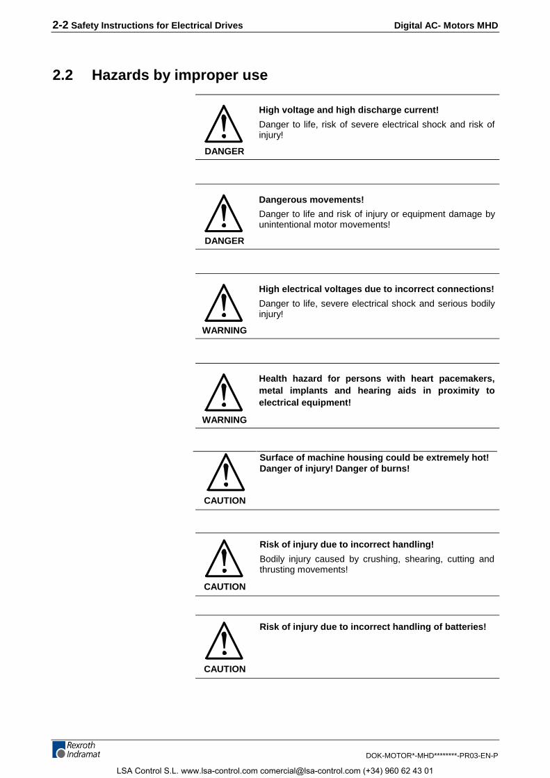
2.2 Hazards by improper use
DANGER
High voltage and high discharge current!
Danger to life, risk of severe electrical shock and risk ofinjury!
DANGER
Dangerous movements!
Danger to life and risk of injury or equipment damage byunintentional motor movements!
WARNING
High electrical voltages due to incorrect connections!
Danger to life, severe electrical shock and serious bodilyinjury!
WARNING
Health hazard for persons with heart pacemakers,metal implants and hearing aids in proximity toelectrical equipment!
CAUTION
Surface of machine housing could be extremely hot!Danger of injury! Danger of burns!
CAUTION
Risk of injury due to incorrect handling!
Bodily injury caused by crushing, shearing, cutting andthrusting movements!
CAUTION
Risk of injury due to incorrect handling of batteries!
LSA Control S.L. www.lsa-control.com [email protected] (+34) 960 62 43 01
Digital AC- Motors MHD Safety Instructions for Electrical Drives 2-3
DOK-MOTOR*-MHD********-PR03-EN-P
2.3 General
• INDRAMAT GmbH is not liable for damages resulting from failure toobserve the warnings given in these instructions.
• Operating, maintenance and safety instructions in English must beordered and received before initial start-up, if the instructions in thelanguage provided are not understood perfectly.
• Proper and correct transport, storage, assembly, and installation aswell as care in operation and maintenance are prerequisites foroptimal and safe operation of this equipment.
• Trained and qualified personnel in electrical equipment:
Only trained and qualified personnel may work on this equipment or withinits proximity. Personnel are qualified if they have sufficient knowledgeof the assembly, installation, and operation of the product as well asan understanding of all warnings and precautionary measures noted inthese instructions.
Furthermore, they should be trained, instructed, and qualified to switchelectrical circuits and equipment on and off, to ground them, and tomark them according to the requirements of safe work practices andcommon sense. They must have adequate safety equipment and betrained in first aid.
• Use only spare parts approved by the manufacturer.
• All safety regulations and requirements for the specific applicationmust be followed as practiced in the country of use.
• The equipment is designed for installation on commercial machinery.
• Start-up is only permitted once it is sure that the machine in which theproduct is installed complies with the requirements of national safetyregulations and safety specifications of the application.
European countries: see Directive 89/392/EEC (Machine Guideline).
• Operation is only permitted if the national EMC regulations for theapplication are met.
The instructions for installation in accordance with EMC requirements canbe found in the INDRAMAT document "EMC in Drive and ControlSystems“.
The machine builder is responsible for compliance with the limiting valuesas prescribed in the national regulations and specific EMC regulationsfor the application.
European countries: see Directive 89/336/EEC (EMC Guideline).
U.S.A.: See National Electrical Codes (NEC), National ElectricalManufacturers Association (NEMA), and local building codes. Theuser of this equipment must consult the above noted items at all times.
• Technical data, connections, and operational conditions are specifiedin the product documentation and must be followed.
LSA Control S.L. www.lsa-control.com [email protected] (+34) 960 62 43 01
2-4 Safety Instructions for Electrical Drives Digital AC- Motors MHD
DOK-MOTOR*-MHD********-PR03-EN-P
2.4 Protection against contact with electrical parts and notgrounded enclosures
Note: This section pertains to equipment and drive components withvoltages over 50 Volts.
Touching live parts with potentials of 50 volts and higher applied to themor touching not grounded enclosures can be dangerous and cause severeelectrical shock. In order for electrical equipment to be operated, certainparts must have dangerous voltages applied to them.
DANGER
High Voltage!Danger to life, severe electrical shock and risk of injury!
⇒ Only those trained and qualified to work with or onelectrical equipment are permitted to operate, maintainand / or repair this equipment.
⇒ Follow general construction and safety regulationswhen working on electrical installations.
⇒ Before switching on power, the ground wire must bepermanently connected to all electrical units accordingto the connection diagram.
⇒ At no time may electrical equipment be operated if theground wire is not permanently connected, even forbrief measurements or tests.
⇒ Before beginning any work, disconnect mains or thevoltage source from the equipment. Lock theequipment against being switched on while work isbeing performed.
⇒ Wait five (5) minutes after switching off power to allowcapacitors to discharge before beginning work.Measure the voltage on the capacitors beforebeginning work to make sure that the equipment is safeto touch.
⇒ Never touch the electrical connection points of acomponent while power is turned on.
⇒ Before switching the equipment on, install those coversand guards provided with the equipment to preventcontact with live parts. Before operating, cover andguard live parts properly so they cannot be touched.
⇒ A residual-current-operated protective device (r.c.d.)must not be used on an AC drive! Indirect contact mustbe prevented by other means, for example, by anovercurrent protective device.
European countries: according to EN 50178/ 1994.⇒ Electrical components with exposed live parts must be
installed in a control cabinet to prevent direct contact.European countries: according to EN 50178/ 1994.U.S.A: See National Electrical Codes (NEC), NationalElectrical Manufacturers Association (NEMA), and localbuilding codes. The user of this equipment must consultthe above noted items at all times.
LSA Control S.L. www.lsa-control.com [email protected] (+34) 960 62 43 01
Digital AC- Motors MHD Safety Instructions for Electrical Drives 2-5
DOK-MOTOR*-MHD********-PR03-EN-P
DANGER
High housing voltage! High leakage current!Danger to life and limb, danger of injury from electricshock!
⇒ Prior to powering up, connect the electrical equipment,the housing of all electrical units and motors to theprotective conductor at the grounding points or groundthem. This applies even to brief tests.
⇒ The protective conductor of the electrical equipmentand units must always be connected to the supplynetwork. Leakage current exceeds 3.5 mA.
⇒ Use at least a 10 mm2 copper conductor cross sectionfor this protective connection over its entire course!
⇒ Prior to startups, even for brief tests, always connectthe protective conductor or connect with ground wire.High voltage levels can occur on the housing that couldlead to severe electrical shock and personal injury.
European countries: EN 50178 / 1994, section 5.3.2.3.USA: See National Electrical Codes (NEC), NationalElectrical Manufacturers Association (NEMA), and localbuilding codes. The user of this equipment must consultthe above noted items at all times.
2.5 Protection by protective low voltage (PELV) againstelectrical shock
All connections and terminals with voltages ranging between 5 and 50volts on INDRAMAT products are protective low voltages designed inaccordance with the following standards on contact safety:
• International: IEC 364-4-411.1.5
• EU countries: see EN 50178/1994, section 5.2.8.1.
WARNING
High electrical voltages due to incorrect connections!Danger to life, severe electrical shock and/or seriousbodily injury!
⇒ Only that equipment or those electrical componentsand cables may be connected to all terminals andclamps with 0 to 50 volts that are of the protective lowvoltage type (PELV = Protective Extra Low Voltage).
⇒ Only connect those voltages and electrical circuits thatare safely isolated. Safe isolation is achieved, forexample, with an isolating transformer, anoptoelectronic coupler or when battery-operated.
LSA Control S.L. www.lsa-control.com [email protected] (+34) 960 62 43 01
2-6 Safety Instructions for Electrical Drives Digital AC- Motors MHD
DOK-MOTOR*-MHD********-PR03-EN-P
2.6 Protection against dangerous movements
Dangerous movements can be caused when units have bad interfaces ormotors are connected incorrectly.
There are various causes of dangerous movements:
• Improper or incorrect wiring or cable connections
• equipment is operated incorrectly
• probe parameters or encoder parameters are set incorrectly
• malfunctioning components
• errors in software or firmware
Dangerous movements can occur immediately after equipment isswitched on or even after an unspecified time of trouble-free operation.
Although the monitoring circuits in the drive components make improperoperation almost impossible, personnel safety requires that proper safetyprecautions be taken to minimize the risk of personal injury and/orproperty damage. This means that unexpected motion must beanticipated since safety monitoring built into the equipment might bedefeated by incorrect wiring or other faults.
DANGER
Dangerous movements!Danger to life and risk of injury or equipment damage!
⇒ In the drive component monitoring units, every effort ismade to avoid the possibility of faulty operation inconnected drives. Unintended machine motion or othermalfunction is possible if monitoring units are disabled,bypassed or not activated.
⇒ Safe requirements of each individual drive applicationmust be considered on a case-by-case basis by usersand machine builders.
Avoiding accidents, personal injury and/or propertydamage:
⇒ Keep free and clear of the machine’s range of motionand moving parts. Prevent people from accidentallyentering the machine’s range of movement:
- use protective fences- use protective railings- install protective coverings- install light curtains / barriers
⇒ Fences should be strong enough to withstandmaximum possible momentum.
⇒ Mount the Emergency Stop (E-stop) switch in theimmediate reach of the operator. Verify that theemergency stop works before startup. Do not operatethe machine if it is not working.
⇒ Isolate the drive power connection by means of anemergency stop circuit or use a start inhibit system toprevent unintentional start-up.
LSA Control S.L. www.lsa-control.com [email protected] (+34) 960 62 43 01
Digital AC- Motors MHD Safety Instructions for Electrical Drives 2-7
DOK-MOTOR*-MHD********-PR03-EN-P
⇒ Make sure that the drives are brought to standstillbefore accessing or entering the danger zone.
⇒ Disconnect electrical power to the equipment using amaster lock-out and secure against reconnection for:
- maintenance and repair work- cleaning of equipment- long periods of discontinued equipment use
⇒ Avoid operating high-frequency, remote control, andradio equipment near equipment electronics andsupply leads. If use of such equipment cannot beavoided, verify the system and the plant for possiblemalfunctions at all possible positions of normal usebefore the first start-up. If necessary, perform aspecial Electromagnetic Compatibility (EMC) test onthe plant.
2.7 Protection against magnetic and electromagnetic fieldsduring operations and mounting
Magnetic and electromagnetic fields in the vicinity of current-carryingconductors and permanent motor magnets represent a serious healthhazard to persons with heart pacemakers, metal implants and hearingaids.
WARNING
Health hazard for persons with heart pacemakers,metal implants and hearing aids in proximity toelectrical equipment!⇒ Persons with pacemakers and metal implants are not
permitted to have access to the following areas:− Areas in which electrical equipment and parts are
mounted, being operated or started up.− Areas in which parts of motors with permanent
magnets are being stored, repaired or mounted.⇒ If it is necessary for a person with a pacemaker to enter
into such an area, then a physician must be consultedprior to doing so.
⇒ Persons with metal implants or hearing aids must takecare prior to entering into areas described above. It isassumed that metal implants or hearing aids will beaffected by such areas: A physician must be consultedprior to working in and/or entering such areas.
LSA Control S.L. www.lsa-control.com [email protected] (+34) 960 62 43 01
2-8 Safety Instructions for Electrical Drives Digital AC- Motors MHD
DOK-MOTOR*-MHD********-PR03-EN-P
2.8 Protection against contact with hot parts
2.9 Protection during handling and installation
All INDRAMAT products should be handled and assembled according tothe instructions in the documentation.
CAUTION
Risk of injury due to incorrect handling!Bodily injury caused by crushing, shearing, cutting, andthrusting movements!
⇒ Observe installation instructions and safety regulationsbefore handling and working on the product.
⇒ Use suitable lifting or moving equipment duringinstallation. Refer to the user manual for the product.
⇒ Take precautions to avoid pinching and crushing.⇒ Only use suitable tools specified in the user manuals
and use them according the instructions.⇒ Use lifting devices and tools correctly and safely.⇒ Wear appropriate protective clothing, e.g., protective
goggles, safety shoes, protective gloves.⇒ Never stand under suspended loads.⇒ Clean up liquids form the floor to prevent personnel
from slipping.
LSA Control S.L. www.lsa-control.com [email protected] (+34) 960 62 43 01
Digital AC- Motors MHD Safety Instructions for Electrical Drives 2-9
DOK-MOTOR*-MHD********-PR03-EN-P
2.10 Battery safety
Batteries contain reactive chemicals. Incorrect handling can result ininjury or equipment damage.
CAUTION
Risk of injury due to incorrect handling!
⇒ Do not attempt to reactivate dead batteries by heatingor other methods (danger of explosion and corrosion).
⇒ Never charge batteries (danger from leakage andexplosion).
⇒ Never throw batteries into a fire.⇒ Do not take batteries apart.⇒ Handle carefully. Incorrect extraction or installation of a
battery can damage equipment.
Note: Environmental protection and disposal! The batteries contained inthe product should be considered as hazardous material for land,air and sea transport in the sense of the legal requirements(Danger of explosion). Dispose of batteries separately from otherrefuse. Observe the legal requirements in the country ofinstallation.
LSA Control S.L. www.lsa-control.com [email protected] (+34) 960 62 43 01
2-10 Safety Instructions for Electrical Drives Digital AC- Motors MHD
DOK-MOTOR*-MHD********-PR03-EN-P
LSA Control S.L. www.lsa-control.com [email protected] (+34) 960 62 43 01
Digital AC- Motors MHD Integrating Mechanically into the Installation 3-1
DOK-MOTOR*-MHD********-PR03-EN-P
3 Integrating Mechanically into the Installation
3.1 Installation Elevation and Ambient Temperature
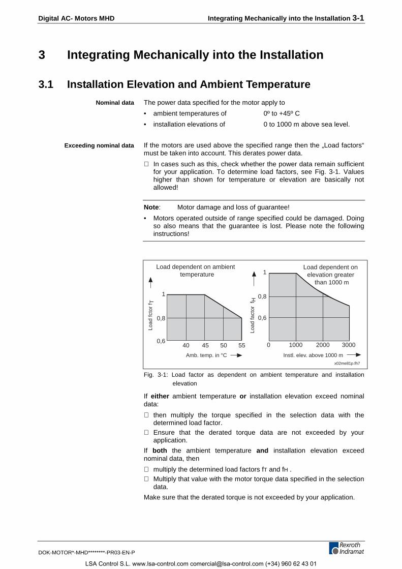
The power data specified for the motor apply to
• ambient temperatures of 0º to +45º C
• installation elevations of 0 to 1000 m above sea level.
If the motors are used above the specified range then the „Load factors“must be taken into account. This derates power data.
⇒ In cases such as this, check whether the power data remain sufficientfor your application. To determine load factors, see Fig. 3-1. Valueshigher than shown for temperature or elevation are basically notallowed!
Note: Motor damage and loss of guarantee!
• Motors operated outside of range specified could be damaged. Doingso also means that the guarantee is lost. Please note the followinginstructions!
x02me81p.fh7
Load dependent on ambienttemperature
Load dependent onelevation greater
than 1000 m
Load
fcto
r f T
Load
fact
or f
H
Amb. temp. in °C Instl. elev. above 1000 m
1000 2000 3000
0,6
0,8
1
0,6
0,8
1
40 45 50 55 0
Fig. 3-1: Load factor as dependent on ambient temperature and installationelevation
If either ambient temperature or installation elevation exceed nominaldata:
⇒ then multiply the torque specified in the selection data with thedetermined load factor.
⇒ Ensure that the derated torque data are not exceeded by yourapplication.
If both the ambient temperature and installation elevation exceednominal data, then
⇒ multiply the determined load factors fT and fH .⇒ Multiply that value with the motor torque data specified in the selection
data.
Make sure that the derated torque is not exceeded by your application.
Nominal data
Exceeding nominal data
LSA Control S.L. www.lsa-control.com [email protected] (+34) 960 62 43 01
3-2 Integrating Mechanically into the Installation Digital AC- Motors MHD
DOK-MOTOR*-MHD********-PR03-EN-P
3.2 Protection Category
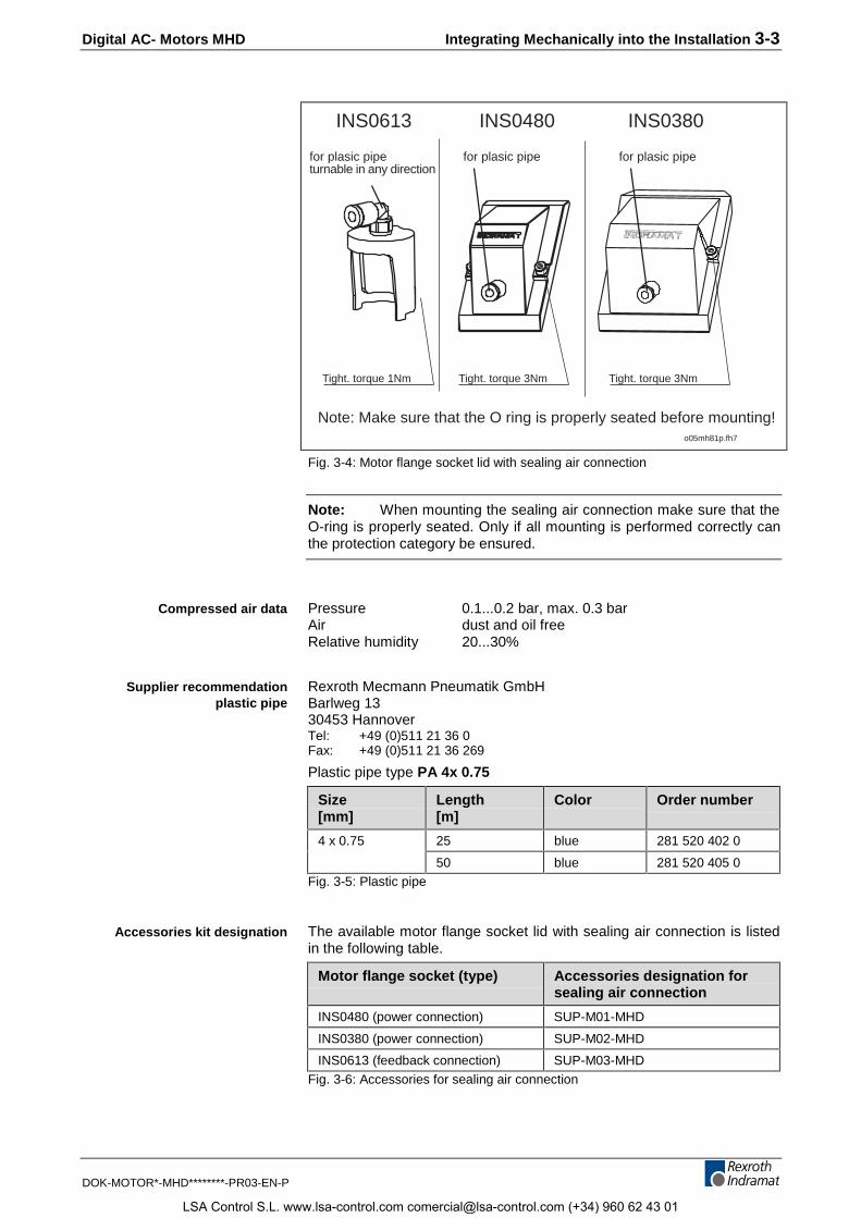
The design of MHD motors meets the following protection categories asspecified in DIN VDE 0470, part 1, edition dated 11/1992 (EN 60 529):
Motor ranges Protection Comment
Motor housing, drive shaft, powerand feedback connections (onlywith correct mounting)
about IP67 with sealing air option
Motor housing, drive shaft, powerand feedback connections (onlywith correct mounting)
IP 65 Standard
Blower motor IP 44 Standard
Surface blower (blower grid) andblower connection
IP 24 Standard
Fig. 3-2: Protection categories of the motors
The protection category is specified with IP (International Protection) andtwo numbers for the level of protection.
The first number describes the protection against contact andpenetration of extrinsic objects. The second one describes the level ofprotection against water.
Firstnumber
Protection
6 protection against dust penetration (dust proof); completeprotection against contact
4 protection against penetration of solid extrinsic objects havinga diameter exceeding 1 mm
2 protection against penetration of solid extrinsic objects havinga diameter exceeding 12 mm⇒ Keep fingers or similar objects away from unit!
Secondnumber
Protection
7 protection against damaging effects with brief submersionsinto water
5 protection against a jet of water from a nozzle comging fromall directions pointed at housing (jet of water)
4 protection against water coming from all directions against thehousing
Fig. 3-3: IP protection categories
Note: The checks for the second number are conducted with freshwater. If cleaning processes use higher pressure or solvents, lubricantsor other types of oils, then a higher protection category may becomenecessary.
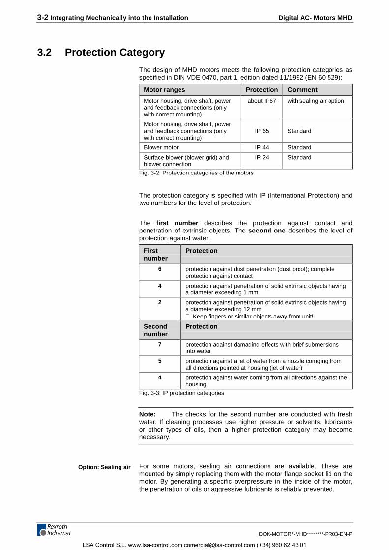
For some motors, sealing air connections are available. These aremounted by simply replacing them with the motor flange socket lid on themotor. By generating a specific overpressure in the inside of the motor,the penetration of oils or aggressive lubricants is reliably prevented.
Option: Sealing air
LSA Control S.L. www.lsa-control.com [email protected] (+34) 960 62 43 01
Digital AC- Motors MHD Integrating Mechanically into the Installation 3-3
DOK-MOTOR*-MHD********-PR03-EN-P
for plasic pipeturnable in any direction
o05mh81p.fh7
Tight. torque 1Nm
INS0613 INS0480 INS0380
Tight. torque 3Nm Tight. torque 3Nm
Note: Make sure that the O ring is properly seated before mounting!
for plasic pipe for plasic pipe
Fig. 3-4: Motor flange socket lid with sealing air connection
Note: When mounting the sealing air connection make sure that theO-ring is properly seated. Only if all mounting is performed correctly canthe protection category be ensured.
Pressure 0.1...0.2 bar, max. 0.3 barAir dust and oil freeRelative humidity 20...30%
Rexroth Mecmann Pneumatik GmbHBarlweg 1330453 HannoverTel: +49 (0)511 21 36 0Fax: +49 (0)511 21 36 269
Plastic pipe type PA 4x 0.75
Size[mm]
Length[m]
Color Order number
4 x 0.75 25 blue 281 520 402 0
50 blue 281 520 405 0Fig. 3-5: Plastic pipe
The available motor flange socket lid with sealing air connection is listedin the following table.
Motor flange socket (type) Accessories designation forsealing air connection
INS0480 (power connection) SUP-M01-MHD
INS0380 (power connection) SUP-M02-MHD
INS0613 (feedback connection) SUP-M03-MHD
Fig. 3-6: Accessories for sealing air connection
Compressed air data
Supplier recommendationplastic pipe
Accessories kit designation
LSA Control S.L. www.lsa-control.com [email protected] (+34) 960 62 43 01
3-4 Integrating Mechanically into the Installation Digital AC- Motors MHD
DOK-MOTOR*-MHD********-PR03-EN-P
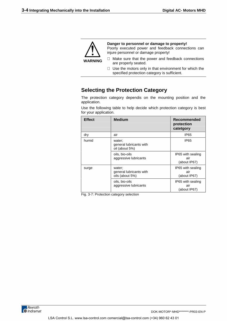
WARNING
Danger to personnel or damage to property!Poorly executed power and feedback connections caninjure personnel or damage property!
⇒ Make sure that the power and feedback connectionsare properly seated.
⇒ Use the motors only in that environment for which thespecified protection category is sufficient.
Selecting the Protection CategoryThe protection category dependis on the mounting position and theapplication.
Use the following table to help decide which protection category is bestfor your application.
Effect Medium Recommendedprotectioncatetgory
dry air IP65
humid water;general lubricants withoil (about 5%)
IP65
oils, bio-oilsaggressive lubricants
IP65 with sealingair
(about IP67)
surge water;general lubricants withoils (about 5%)
IP65 with sealingair
(about IP67)
oils, bio-oilsaggressive lubricants
IP65 with sealingair
(about IP67)Fig. 3-7: Protection category selection
LSA Control S.L. www.lsa-control.com [email protected] (+34) 960 62 43 01
Digital AC- Motors MHD Integrating Mechanically into the Installation 3-5
DOK-MOTOR*-MHD********-PR03-EN-P
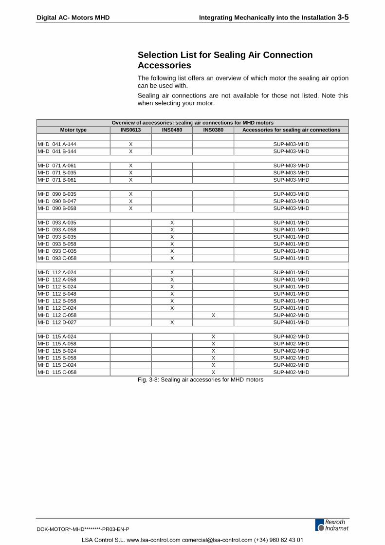
Selection List for Sealing Air ConnectionAccessoriesThe following list offers an overview of which motor the sealing air optioncan be used with.
Sealing air connections are not available for those not listed. Note thiswhen selecting your motor.
Overview of accessories: sealing air connections for MHD motorsMotor type INS0613 INS0480 INS0380 Accessories for sealing air connections
MHD 041 A-144 X SUP-M03-MHDMHD 041 B-144 X SUP-M03-MHD
MHD 071 A-061 X SUP-M03-MHDMHD 071 B-035 X SUP-M03-MHDMHD 071 B-061 X SUP-M03-MHD
MHD 090 B-035 X SUP-M03-MHDMHD 090 B-047 X SUP-M03-MHDMHD 090 B-058 X SUP-M03-MHD
MHD 093 A-035 X SUP-M01-MHDMHD 093 A-058 X SUP-M01-MHDMHD 093 B-035 X SUP-M01-MHDMHD 093 B-058 X SUP-M01-MHDMHD 093 C-035 X SUP-M01-MHDMHD 093 C-058 X SUP-M01-MHD
MHD 112 A-024 X SUP-M01-MHDMHD 112 A-058 X SUP-M01-MHDMHD 112 B-024 X SUP-M01-MHDMHD 112 B-048 X SUP-M01-MHDMHD 112 B-058 X SUP-M01-MHDMHD 112 C-024 X SUP-M01-MHDMHD 112 C-058 X SUP-M02-MHDMHD 112 D-027 X SUP-M01-MHD
MHD 115 A-024 X SUP-M02-MHDMHD 115 A-058 X SUP-M02-MHDMHD 115 B-024 X SUP-M02-MHDMHD 115 B-058 X SUP-M02-MHDMHD 115 C-024 X SUP-M02-MHDMHD 115 C-058 X SUP-M02-MHD
Fig. 3-8: Sealing air accessories for MHD motors
LSA Control S.L. www.lsa-control.com [email protected] (+34) 960 62 43 01
3-6 Integrating Mechanically into the Installation Digital AC- Motors MHD
DOK-MOTOR*-MHD********-PR03-EN-P
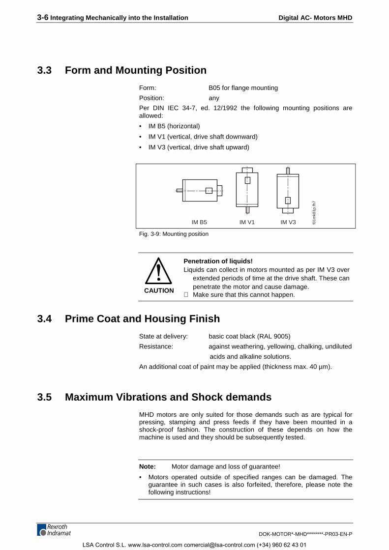
3.3 Form and Mounting Position
Form: B05 for flange mounting
Position: any
Per DIN IEC 34-7, ed. 12/1992 the following mounting positions areallowed:
• IM B5 (horizontal)
• IM V1 (vertical, drive shaft downward)
• IM V3 (vertical, drive shaft upward)
IM B5 IM V1 IM V3 f01m
k81p
.fh7
Fig. 3-9: Mounting position
CAUTION
Penetration of liquids!Liquids can collect in motors mounted as per IM V3 over
extended periods of time at the drive shaft. These canpenetrate the motor and cause damage.
⇒ Make sure that this cannot happen.
3.4 Prime Coat and Housing Finish
State at delivery: basic coat black (RAL 9005)
Resistance: against weathering, yellowing, chalking, undiluted
acids and alkaline solutions.
An additional coat of paint may be applied (thickness max. 40 µm).
3.5 Maximum Vibrations and Shock demands
MHD motors are only suited for those demands such as are typical forpressing, stamping and press feeds if they have been mounted in ashock-proof fashion. The construction of these depends on how themachine is used and they should be subsequently tested.
Note: Motor damage and loss of guarantee!
• Motors operated outside of specified ranges can be damaged. Theguarantee in such cases is also forfeited, therefore, please note thefollowing instructions!
LSA Control S.L. www.lsa-control.com [email protected] (+34) 960 62 43 01
Digital AC- Motors MHD Integrating Mechanically into the Installation 3-7
DOK-MOTOR*-MHD********-PR03-EN-P
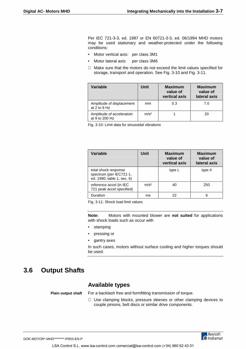
Per IEC 721-3-3, ed. 1987 or EN 60721-3-3, ed. 06/1994 MHD motorsmay be used stationary and weather-protected under the followingconditions:
• Motor vertical axis: per class 3M1
• Motor lateral axis: per class 3M6
⇒ Make sure that the motors do not exceed the limit values specified forstorage, transport and operation. See Fig. 3-10 and Fig. 3-11.
Variable Unit Maximumvalue of
vertical axis
Maximumvalue of
lateral axis
Amplitude of displacementat 2 to 9 Hz
mm 0.3 7.0
Amplitude of acceleratoinat 9 to 200 Hz
m/s² 1 20
Fig. 3-10: Limit data for sinusoidal vibrations
Variable Unit Maximumvalue of
vertical axis
Maximumvalue of
lateral axis
total shock responsespectrum (per IEC721-1,ed. 1990; table 1, sec. 6)
type L type II
reference accel (in IEC721 peak accel specified)
m/s² 40 250
Duration ms 22 6
Fig. 3-11: Shock load limit values
Note: Motors with mounted blower are not suited for applicationswith shock loads such as occur with
• stamping
• pressing or
• gantry axes
In such cases, motors without surface cooling and higher torques shouldbe used.
3.6 Output Shafts
Available typesFor a backlash free and formfitting transmission of torque.
⇒ Use clamping blocks, pressure sleeves or other clamping devices tocouple pinions, belt discs or similar drive components.
Plain output shaft
LSA Control S.L. www.lsa-control.com [email protected] (+34) 960 62 43 01

3-8 Integrating Mechanically into the Installation Digital AC- Motors MHD
DOK-MOTOR*-MHD********-PR03-EN-P
(Per DIN 6885, sh.1; ed. 08/1968). For formfitting transmission of torquewith low demands made of shaft/hub connection.
Note: Shaft could be damaged!
• During forceful reverse operatoins, the keyway could swing out. Anydeformations within this area can then lead to a break in the shaft. It istherefore advisable to use a plain output shaft.
Shaft loadRadial and axial forces effect the output shaft:
Faxial
Fradial
x
X03MH81P.fh7
Fig. 3-12: Shaft load forces
Note: Motor damage and loss of guarantee!
• Excessive shaft loads can damage the motors and shorten bearingservice life. The guarantee is also lost, therefore, please note thefollowing instructions!
The maximum allowed radial force Fradial_max depends on shaft break load.It is determined in terms of distance x of the point of application of forceand the design of the output shaft (plain shaft or one with keyway).
Sections to contain ”Data to detrermine maximum shaft load“ sections.
⇒ Using those characteristics determine maximum allowed radial forceFradial_max for your application.
⇒ Make sure that the radial force determined is not exceeded at anytime during operation.
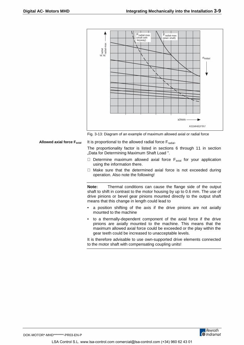
The allowed radial force Fradial depends on the bearing service lifewanted. It is fixed in terms of the arithmetically determined speed of themotor nmittel and distance x of the point of application of force (see Fig. 3-13).
Sections 6 to 11 contain ”Data to determine maximum shaft load“sections.
⇒ Using those characteristics determine maximum allowed radial forceFradial_max for your application.
⇒ Make sure that the radial force determined is not exceeded at anytime during operation.
Output shaft with keyway
Maximum allowed radial forceFradial_max
Allowed radial force Fradial
LSA Control S.L. www.lsa-control.com [email protected] (+34) 960 62 43 01
Digital AC- Motors MHD Integrating Mechanically into the Installation 3-9
DOK-MOTOR*-MHD********-PR03-EN-P
x/mm
nmittel
Fra
dial
Fra
dial
-max
Fradial-max (shaft with keyway)
Fradial-max (plain shaft)
K01MH81P.fh7
Fig. 3-13: Diagram of an example of maximum allowed axial or radial force
It is proportional to the allowed radial force Fradial.
The proportionality factor is listed in sections 6 through 11 in section„Data for Determining Maximum Shaft Load ".
⇒ Determine maximum allowed axial force Faxial for your applicationusing the information there.
⇒ Make sure that the determined axial force is not exceeded duringoperation. Also note the following!
Note: Thermal conditions can cause the flange side of the outputshaft to shift in contrast to the motor housing by up to 0.6 mm. The use ofdrive pinions or bevel gear pinions mounted directly to the output shaftmeans that this change in length could lead to
• a position shifting of the axis if the drive pinions are not axiallymounted to the machine
• to a thermally-dependent component of the axial force if the drivepinions are axially mounted to the machine. This means that themaximum allowed axial force could be exceeded or the play within thegear teeth could be increased to unacceptable levels.
It is therefore advisable to use own-supported drive elements connectedto the motor shaft with compensating coupling units!
Allowed axial force Faxial
LSA Control S.L. www.lsa-control.com [email protected] (+34) 960 62 43 01
3-10 Integrating Mechanically into the Installation Digital AC- Motors MHD
DOK-MOTOR*-MHD********-PR03-EN-P
If the allowed radial and axial forces are not exceeded, then it applies tothe nominal bearing service lifespan:
L10h = 30,000 operating hours (computed per ISO 281, ed. 12/1990).
Lifespan otherwise is derated:
LF
F10h
radial
radial ist=
⋅_
3
30000
L10h: bearing lifespan (per ISO 281, ed. 12/1990)Fradial: determined allowed radial force in NFradial_ist: actual effective radial force in N
Fig. 3-14: Computing bearing lifespan L10h if allowed radial force Fradial isexceeded
Note: The actually effective radial force Fradial_ist may not exceedmaximum allowed radial force Fradial_max.
Note: When mounting drive elements to an output shaft anoverdefined bearing must be avoided. The inevitable tolerances generateadditional forces applied to the bearings of the motor shaft and thus to aclearly shorter service life. If such a construction cannot be avoided, thenplease consult INDRAMAT!
3.7 Surface Cooling
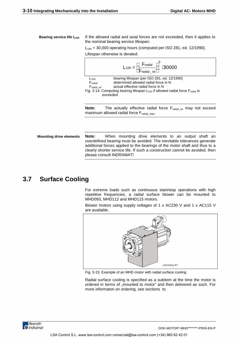
For extreme loads such as continuous start/stop operations with highrepetitive frequencies, a radial surface blower can be mounted toMHD093, MHD112 and MHD115 motors.
Blower motors using supply voltages of 1 x AC230 V and 1 x AC115 Vare available.
o02mh81p.fh7
Fig. 3-15: Example of an MHD motor with radial surface cooling
Radial surface cooling is specified as a subitem at the time the motor isordered in terms of „mounted to motor” and then delivered as such. Formore informaton on ordering, see sections to.
Bearing service life L10h
Mounting drive elements
LSA Control S.L. www.lsa-control.com [email protected] (+34) 960 62 43 01
Digital AC- Motors MHD Integrating Mechanically into the Installation 3-11
DOK-MOTOR*-MHD********-PR03-EN-P
Note: Motors with mounted blower units are not suited for such asapplications with shock loads that exist with
• stamping
• pressing or
• gantry axes
In such cases, use motors without surface cooling and higher torques.
3.8 Liquid-Cooled MHD Motors
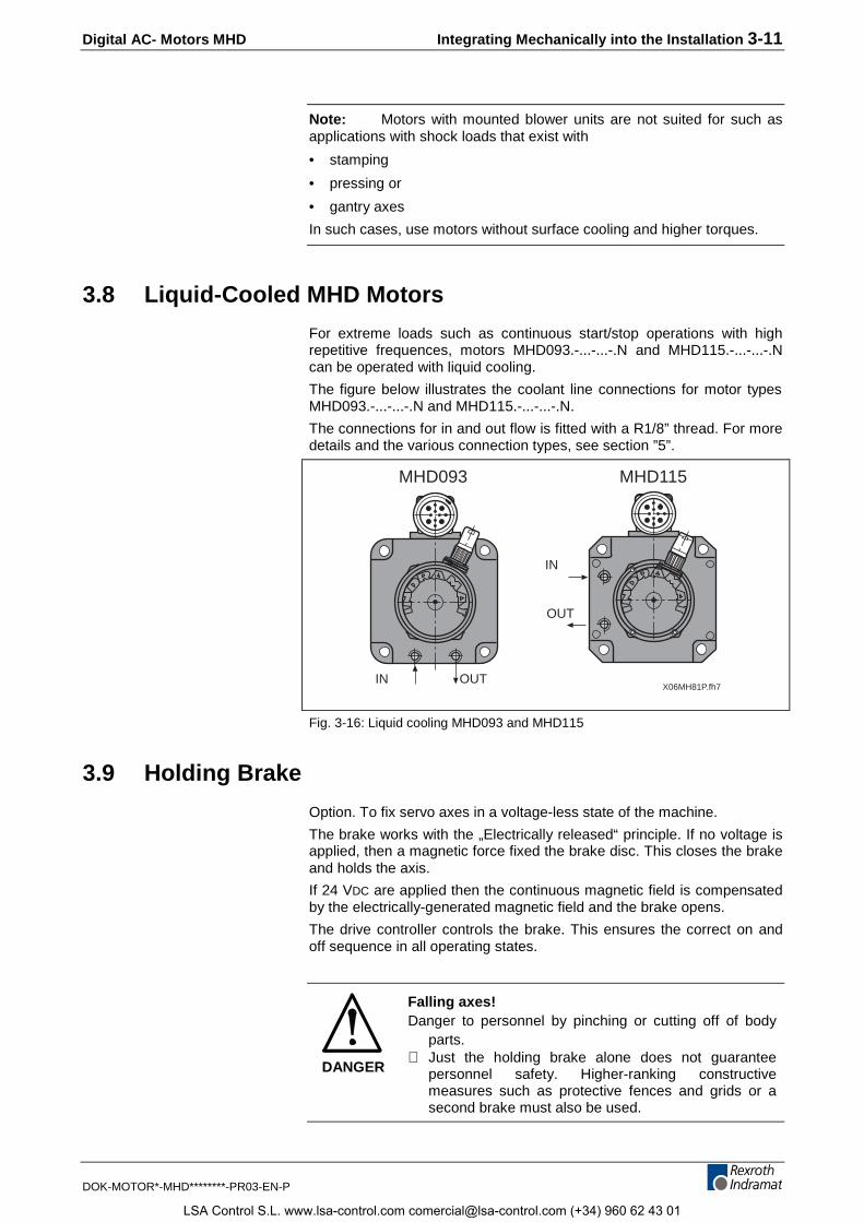
For extreme loads such as continuous start/stop operations with highrepetitive frequences, motors MHD093.-...-...-.N and MHD115.-...-...-.Ncan be operated with liquid cooling.
The figure below illustrates the coolant line connections for motor typesMHD093.-...-...-.N and MHD115.-...-...-.N.
The connections for in and out flow is fitted with a R1/8” thread. For moredetails and the various connection types, see section ”5”.
MHD093
IN OUT
IN
OUT
MHD115
X06MH81P.fh7
Fig. 3-16: Liquid cooling MHD093 and MHD115
3.9 Holding Brake
Option. To fix servo axes in a voltage-less state of the machine.
The brake works with the „Electrically released“ principle. If no voltage isapplied, then a magnetic force fixed the brake disc. This closes the brakeand holds the axis.
If 24 VDC are applied then the continuous magnetic field is compensatedby the electrically-generated magnetic field and the brake opens.
The drive controller controls the brake. This ensures the correct on andoff sequence in all operating states.
DANGER
Falling axes!Danger to personnel by pinching or cutting off of body
parts.⇒ Just the holding brake alone does not guarantee
personnel safety. Higher-ranking constructivemeasures such as protective fences and grids or asecond brake must also be used.
LSA Control S.L. www.lsa-control.com [email protected] (+34) 960 62 43 01
3-12 Integrating Mechanically into the Installation Digital AC- Motors MHD
DOK-MOTOR*-MHD********-PR03-EN-P
Note: Premature wear of holding brake is possible!
• The brake wears down after about 20,000 revolutions of the motor in aclosed state. Therefore, do not use the holding brake as if it were anormal brake to stop a moving axis. This is only permitted in anemergency stop situation.
Holding torque must be checked prior to start up.
Note: If motors have been stored for extended periods, then thetransferrable torque of the holding brake must be checked before themotor is used. If the holding torque specified in the data sheets is notreached, then the brake must be re-finished.
⇒ Please note data in section „brake“.
LSA Control S.L. www.lsa-control.com [email protected] (+34) 960 62 43 01
Digital AC- Motors MHD Integrating Mechanically into the Installation 3-13
DOK-MOTOR*-MHD********-PR03-EN-P
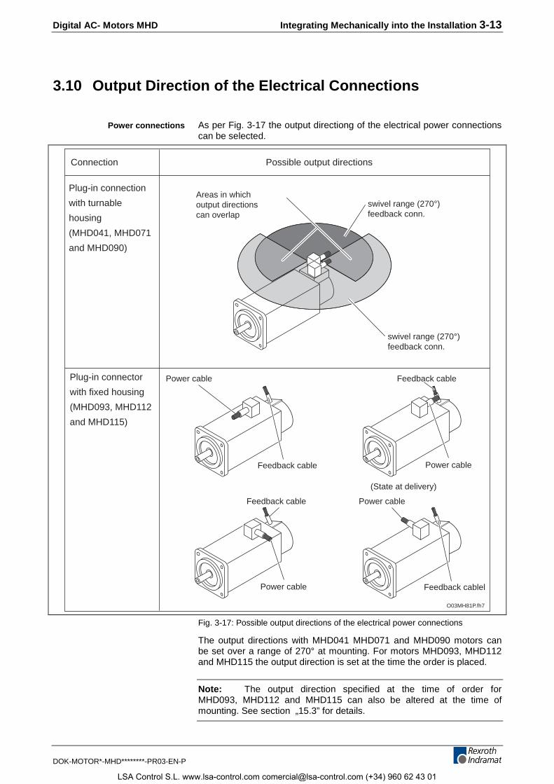
3.10 Output Direction of the Electrical Connections
As per Fig. 3-17 the output directiong of the electrical power connectionscan be selected.
O03MH81P.fh7
Connection Possible output directions
Plug-in connector
with fixed housing
(MHD093, MHD112
and MHD115)
Power cable
Feedback cable Power cable
(State at delivery)
Feedback cable
Feedback cable Power cable
Power cable Feedback cablel
Plug-in connection
with turnable
housing
(MHD041, MHD071
and MHD090)
swivel range (270°)feedback conn.
swivel range (270°)feedback conn.
Areas in whichoutput directionscan overlap
Fig. 3-17: Possible output directions of the electrical power connections
The output directions with MHD041 MHD071 and MHD090 motors canbe set over a range of 270° at mounting. For motors MHD093, MHD112and MHD115 the output direction is set at the time the order is placed.
Note: The output direction specified at the time of order forMHD093, MHD112 and MHD115 can also be altered at the time ofmounting. See section „15.3” for details.
Power connections
LSA Control S.L. www.lsa-control.com [email protected] (+34) 960 62 43 01
3-14 Integrating Mechanically into the Installation Digital AC- Motors MHD
DOK-MOTOR*-MHD********-PR03-EN-P
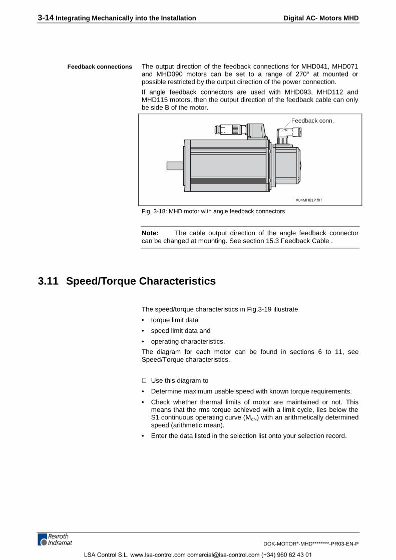
The output direction of the feedback connections for MHD041, MHD071and MHD090 motors can be set to a range of 270° at mounted orpossible restricted by the output direction of the power connection.
If angle feedback connectors are used with MHD093, MHD112 andMHD115 motors, then the output direction of the feedback cable can onlybe side B of the motor.
X04MH81P.fh7
Feedback conn.
Fig. 3-18: MHD motor with angle feedback connectors
Note: The cable output direction of the angle feedback connectorcan be changed at mounting. See section 15.3 Feedback Cable .
3.11 Speed/Torque Characteristics
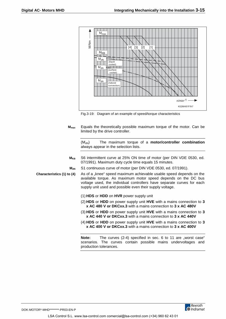
The speed/torque characteristics in Fig.3-19 illustrate
• torque limit data
• speed limit data and
• operating characteristics.
The diagram for each motor can be found in sections 6 to 11, seeSpeed/Torque characteristics.
⇒ Use this diagram to
• Determine maximum usable speed with known torque requirements.
• Check whether thermal limits of motor are maintained or not. Thismeans that the rms torque achieved with a limit cycle, lies below theS1 continuous operating curve (MdN) with an arithmetically determinedspeed (arithmetic mean).
• Enter the data listed in the selection list onto your selection record.
Feedback connections
LSA Control S.L. www.lsa-control.com [email protected] (+34) 960 62 43 01
Digital AC- Motors MHD Integrating Mechanically into the Installation 3-15
DOK-MOTOR*-MHD********-PR03-EN-P
K02MH81P.fh7
n/min-1
M/N
m
Mmax
MKB
[1][2][3][4]
(naturalconvection)
MdN(surface cooled)
MdN
MdN(liquidcooled)
Fig.3-19: Diagram of an example of speed/torque characteristics
Equals the theoretically possible maximum torque of the motor. Can belimited by the drive controller.
(MdN) The maximum torque of a motor/controller combinationalways appear in the selection lists.
S6 intermittent curve at 25% ON time of motor (per DIN VDE 0530, ed.07/1991). Maximum duty cycle time equals 15 minutes.
S1 continuous curve of motor (per DIN VDE 0530, ed. 07/1991).
As of a „knee“ speed maximum achievable usable speed depends on theavailable torque. As maximum motor speed depends on the DC busvoltage used, the individual controllers have separate curves for eachsupply unit used and possible even their supply voltage.
(1) HDS or HDD on HVR power supply unit
(2) HDS or HDD on power supply unit HVE with a mains connection to 3x AC 480 V or DKCxx.3 with a mains connection to 3 x AC 480V
(3) HDS or HDD on power supply unit HVE with a mains connection to 3x AC 440 V or DKCxx.3 with a mains connection to 3 x AC 440V
(4) HDS or HDD on power supply unit HVE with a mains connection to 3x AC 400 V or DKCxx.3 with a mains connection to 3 x AC 400V
Note: The curves (2-4) specified in sec. 6 to 11 are „worst case“scenarios. The curves contain possible mains undervoltages andproduction tolerances.
Mmax
MKB
MdN
Characteristics (1) to (4)
LSA Control S.L. www.lsa-control.com [email protected] (+34) 960 62 43 01
3-16 Integrating Mechanically into the Installation Digital AC- Motors MHD
DOK-MOTOR*-MHD********-PR03-EN-P
LSA Control S.L. www.lsa-control.com [email protected] (+34) 960 62 43 01
Digital AC- Motors MHD Electrical Connections 4-1
DOK-MOTOR*-MHD********-PR03-EN-P
4 Electrical Connections
4.1 An Overview of the Connections
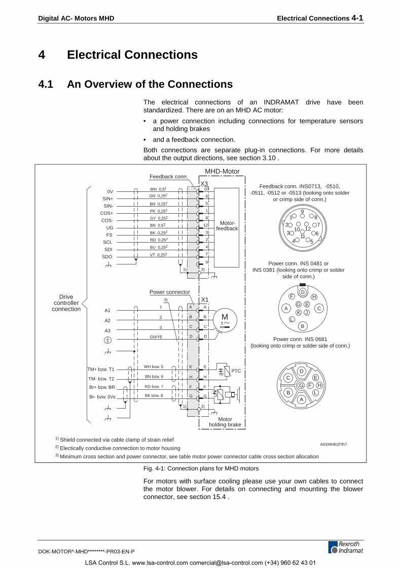
The electrical connections of an INDRAMAT drive have beenstandardized. There are on an MHD AC motor:
• a power connection including connections for temperature sensorsand holding brakes
• and a feedback connection.
Both connections are separate plug-in connections. For more detailsabout the output directions, see section 3.10 .
MHD-Motor
Drivecontroller
connection
A01MH81P.fh7
AB
CD
EHFG
L
A
B
C
A1
A2
A3
M3
Motorholding brake
TM- bzw. T2
PTC
U
Motor-feedback
E
H
F
G
1
2
3
GN/YE
TM+ bzw. T1
Br- bzw. 0VB
Br+ bzw. BR
VT 0,252
BU 0,252
RD 0,252
BK 0,252
GY 0,252
PK 0,252
BN 0,252
GN 0,252
WH 0,52
BN 0,52
10
6
5
1
8
12
3
2
4
7
0V
SIN+
SIN-
COS+
COS-
UG
FS
SCL
SDI
SDO
3)
BK bzw. 8
RD bzw. 7
BN bzw. 6
WH bzw. 5
9
D
A
B
C
D
E
H
F
G
X3
X1
2)
2)
1)
1)
12
3
4 5
6
78
9
1011
12
B
HF
L
CA
D
E
K J
G
Feedback conn. INS0713, -0510,-0511, -0512 or -0513 (looking onto solder
or crimp side of conn.)
Power conn. INS 0481 orINS 0381 (looking onto crimp or solder
side of conn.)
Power conn. INS 0681(looking onto crimp or solder side of conn.)
1) Shield connected via cable clamp of strain relief2) Electically conductive connection to motor housing3) Minimum cross section and power connector, see table motor power connector cable cross section allocation
Power connector
Feedback conn.
Fig. 4-1: Connection plans for MHD motors
For motors with surface cooling please use your own cables to connectthe motor blower. For details on connecting and mounting the blowerconnector, see section 15.4 .
LSA Control S.L. www.lsa-control.com [email protected] (+34) 960 62 43 01
4-2 Electrical Connections Digital AC- Motors MHD
DOK-MOTOR*-MHD********-PR03-EN-P
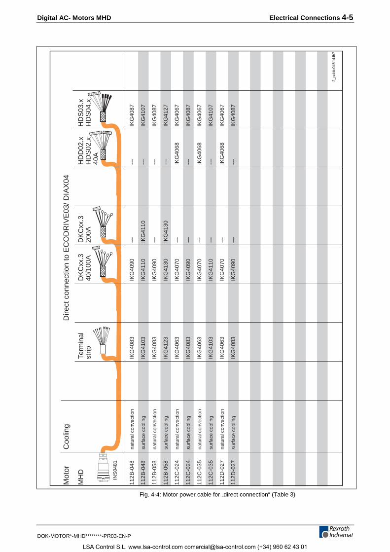
4.2 Power Cables
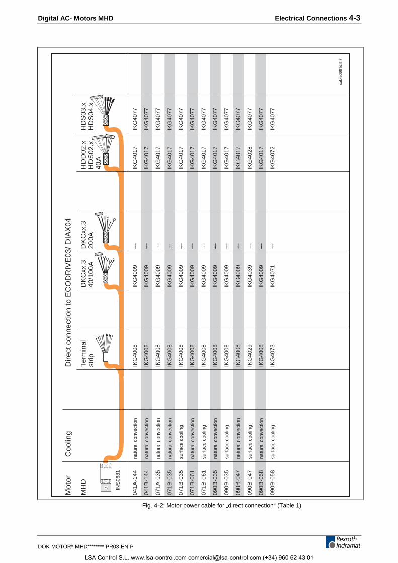
MHD motors are preferrably equipped with standard power cables.
These power cables are available in the following versions:
• direct connections
• connections with intermediate plug-in locations
⇒ The following table lists the cable designations, i.e., orderdesignations, or the motor/controller combinations.
Available cable lengths are 2 to 75 meters.
⇒ To order, simply state the cable length(s) needed. Example: IKG4009/ 10.5 (=power cable for DKCxx.3, length 10.5m).
Note: The maximum total length of the cable connection from motorto drive controller with two intermediate plugs equals 75meters. With several plug-in locations the maximum totallength is reduced. This, however, should be checked to seewhether it is functioning properly or not.
Lengths
LSA Control S.L. www.lsa-control.com [email protected] (+34) 960 62 43 01
Digital AC- Motors MHD Electrical Connections 4-3
DOK-MOTOR*-MHD********-PR03-EN-P
4 3 2 1
7 6 5 4 3 2 1
4 3 2 1
7 6 5 4 3
4 3 2 1
Mot
or C
oolin
gD
irect
con
nect
ion
to E
CO
DR
IVE
03/ D
IAX
04
MH
DTe
rmin
alD
KC
xx.3
DK
Cxx
.3H
DD
02.x
HD
S03
.xst
rip40
/100
A20
0AH
DS
02.x
HD
S04
.x
40
A
041A
-144
natu
ral c
onve
ctio
nIK
G40
08IK
G40
09--
-IK
G40
17IK
G40
77
041B
-144
natu
ral c
onve
ctio
nIK
G40
08IK
G40
09--
-IK
G40
17IK
G40
77
071A
-035
natu
ral c
onve
ctio
nIK
G40
08IK
G40
09--
-IK
G40
17IK
G40
77
071B
-035
natu
ral c
onve
ctio
nIK
G40
08IK
G40
09--
-IK
G40
17IK
G40
77
071B
-035
surf
ace
cool
ing
IKG
4008
IKG
4009
---
IKG
4017
IKG
4077
071B
-061
natu
ral c
onve
ctio
nIK
G40
08IK
G40
09--
-IK
G40
17IK
G40
77
071B
-061
surf
ace
cool
ing
IKG
4008
IKG
4009
---
IKG
4017
IKG
4077
090B
-035
natu
ral c
onve
ctio
nIK
G40
08IK
G40
09--
-IK
G40
17IK
G40
77
090B
-035
surf
ace
cool
ing
IKG
4008
IKG
4009
---
IKG
4017
IKG
4077
090B
-047
natu
ral c
onve
ctio
nIK
G40
08IK
G40
09--
-IK
G40
17IK
G40
77
090B
-047
surf
ace
cool
ing
IKG
4029
IKG
4039
---
IKG
4028
IKG
4077
090B
-058
natu
ral c
onve
ctio
nIK
G40
08IK
G40
09--
-IK
G40
17IK
G40
77
090B
-058
surf
ace
cool
ing
IKG
4073
IKG
4071
---
IKG
4072
IKG
4077
cabl
e068
1d.fh
7
INS
0681
Fig. 4-2: Motor power cable for „direct connection“ (Table 1)
LSA Control S.L. www.lsa-control.com [email protected] (+34) 960 62 43 01
4-4 Electrical Connections Digital AC- Motors MHD
DOK-MOTOR*-MHD********-PR03-EN-P
4 3 2 1
7 6 5 4 3 2 1
4 3 2 1
7 6 5 4 3
4 3 2 1
Mot
or
Coo
ling
Dire
ct c
onne
ctio
n to
EC
OD
RIV
E03
/ DIA
X04
MH
DTe
rmin
alD
KC
xx.3
DK
Cxx
.3H
DD
02.x
HD
S03
.xst
rip40
/100
A20
0AH
DS
02.x
HD
S04
.x
40
A
093A
-024
natu
ral c
onve
ctio
nIK
G40
53IK
G40
60--
-IK
G40
55IK
G40
47
093A
-035
natu
ral c
onve
ctio
nIK
G40
53IK
G40
60--
-IK
G40
55IK
G40
47
093A
-058
natu
ral c
onve
ctio
nIK
G40
53IK
G40
60--
-IK
G40
55IK
G40
47
093B
-035
natu
ral c
onve
ctio
nIK
G40
53IK
G40
60--
-IK
G40
55IK
G40
47
093B
-035
surf
ace
cool
ing
IKG
4053
IKG
4060
---
IKG
4055
IKG
4047
093B
-035
liqui
d co
olin
gIK
G40
63IK
G40
70--
-IK
G40
68IK
G40
67
093B
-058
natu
ral c
onve
ctio
nIK
G40
53IK
G40
60--
-IK
G40
55IK
G40
47
093B
-058
surf
ace
cool
ing
IKG
4083
IKG
4090
---
---
IKG
4087
093B
-058
liqui
d co
olin
gIK
G40
83IK
G40
90--
---
-IK
G40
87
093C
-035
natu
ral c
onve
ctio
nIK
G40
53IK
G40
60--
-IK
G40
55IK
G40
47
093C
-035
surf
ace
cool
ing
IKG
4063
IKG
4070
---
IKG
4068
IKG
4067
093C
-035
liqui
d co
olin
gIK
G40
83IK
G40
90--
---
-IK
G40
87
093C
-058
natu
ral c
onve
ctio
nIK
G40
63IK
G40
70--
-IK
G40
68IK
G40
67
093C
-058
surf
ace
cool
ing
IKG
4083
IKG
4090
---
---
IKG
4087
093C
-058
liqui
d co
olin
gIK
G41
03IK
G41
10IK
G41
10--
-IK
G41
07
112A
-024
natu
ral c
onve
ctio
nIK
G40
53IK
G40
60--
-IK
G40
55IK
G40
47
112A
-058
natu
ral c
onve
ctio
nIK
G40
53IK
G40
60--
-IK
G40
55IK
G40
47
112B
-024
natu
ral c
onve
ctio
nIK
G40
53IK
G40
60--
-IK
G40
55IK
G40
47
112B
-024
surf
ace
cool
ing
IKG
4083
IKG
4090
---
---
IKG
4087
1_ca
ble0
481d
.fh7
INS
0481
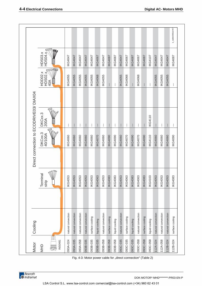
Fig. 4-3: Motor power cable for „direct connection“ (Table 2)
LSA Control S.L. www.lsa-control.com [email protected] (+34) 960 62 43 01
Digital AC- Motors MHD Electrical Connections 4-5
DOK-MOTOR*-MHD********-PR03-EN-P
4 3 2 1
7 6 5 4 3 2 1
4 3 2 1
7 6 5 4 3
4 3 2 1
Mot
or
Coo
ling
Dire
ct c
onne
ctio
n to
EC
OD
RIV
E03
/ DIA
X04
MH
DTe
rmin
alD
KC
xx.3
DK
Cxx
.3H
DD
02.x
HD
S03
.xst
rip40
/100
A20
0AH
DS
02.x
HD
S04
.x
40
A
112B
-048
natu
ral c
onve
ctio
nIK
G40
83IK
G40
90--
---
-IK
G40
87
112B
-048
surf
ace
cool
ing
IKG
4103
IKG
4110
IKG
4110
---
IKG
4107
112B
-058
natu
ral c
onve
ctio
nIK
G40
83IK
G40
90--
---
-IK
G40
87
112B
-058
surf
ace
cool
ing
IKG
4123
IKG
4130
IKG
4130
---
IKG
4127
112C
-024
natu
ral c
onve
ctio
nIK
G40
63IK
G40
70--
-IK
G40
68IK
G40
67
112C
-024
surf
ace
cool
ing
IKG
4083
IKG
4090
---
---
IKG
4087
112C
-035
natu
ral c
onve
ctio
nIK
G40
63IK
G40
70--
-IK
G40
68IK
G40
67
112C
-035
surf
ace
cool
ing
IKG
4103
IKG
4110
---
---
IKG
4107
112D
-027
natu
ral c
onve
ctio
nIK
G40
63IK
G40
70--
-IK
G40
68IK
G40
67
112D
-027
surf
ace
cool
ing
IKG
4083
IKG
4090
---
---
IKG
4087
2_ca
ble0
481d
.fh7
INS
0481
Fig. 4-4: Motor power cable for „direct connection“ (Table 3)
LSA Control S.L. www.lsa-control.com [email protected] (+34) 960 62 43 01
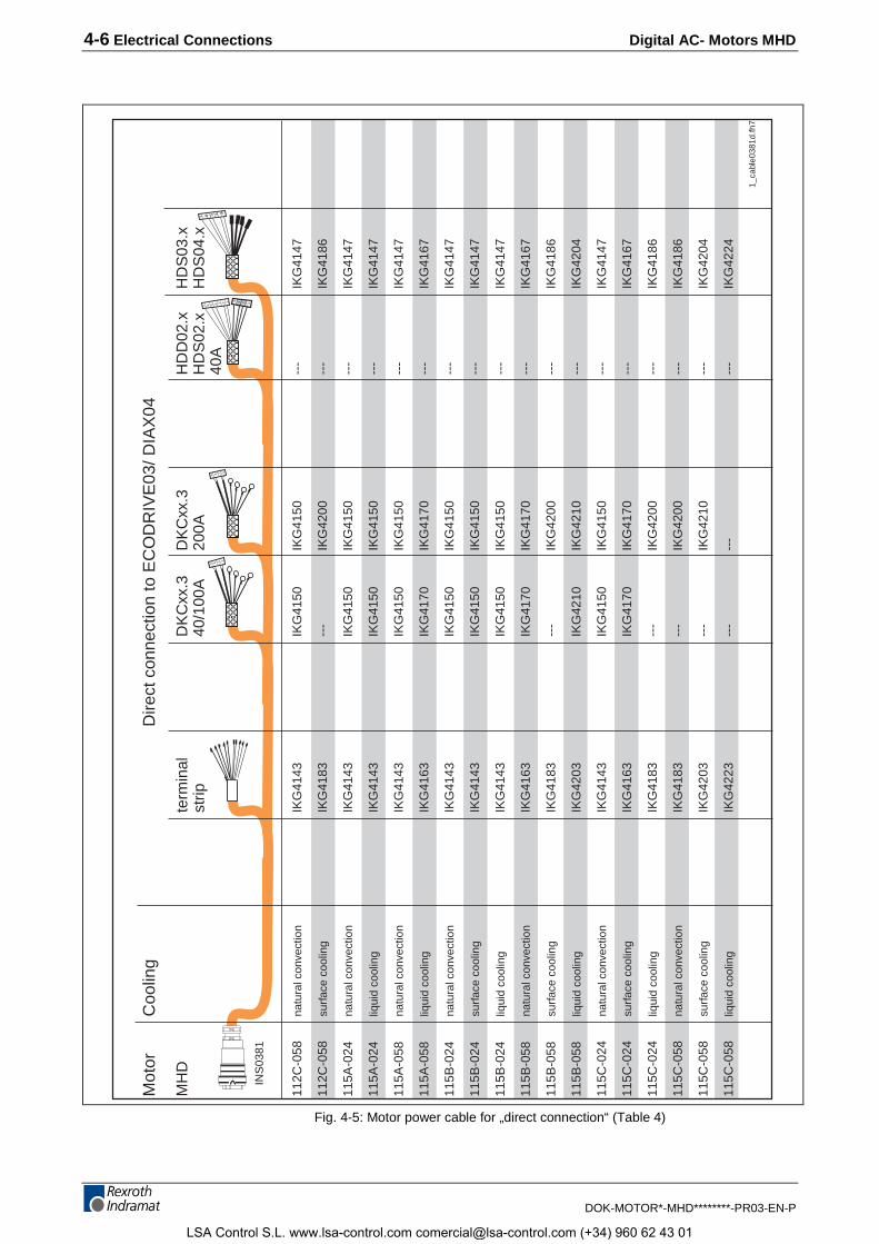
4-6 Electrical Connections Digital AC- Motors MHD
DOK-MOTOR*-MHD********-PR03-EN-P
4 3 2 1
7 6 5 4 3 2 1
4 3 2 1
7 6 5 4 3
4 3 2 1
Mot
or
Coo
ling
Dire
ct c
onne
ctio
n to
EC
OD
RIV
E03
/ DIA
X04
MH
Dte
rmin
alD
KC
xx.3
DK
Cxx
.3H
DD
02.x
HD
S03
.xst
rip40
/100
A20
0AH
DS
02.x
HD
S04
.x
40
A
112C
-058
natu
ral c
onve
ctio
nIK
G41
43IK
G41
50IK
G41
50--
-IK
G41
47
112C
-058
surf
ace
cool
ing
IKG
4183
---
IKG
4200
---
IKG
4186
115A
-024
natu
ral c
onve
ctio
nIK
G41
43IK
G41
50IK
G41
50--
-IK
G41
47
115A
-024
liqui
d co
olin
gIK
G41
43IK
G41
50IK
G41
50--
-IK
G41
47
115A
-058
natu
ral c
onve
ctio
nIK
G41
43IK
G41
50IK
G41
50--
-IK
G41
47
115A
-058
liqui
d co
olin
gIK
G41
63IK
G41
70IK
G41
70--
-IK
G41
67
115B
-024
natu
ral c
onve
ctio
nIK
G41
43IK
G41
50IK
G41
50--
-IK
G41
47
115B
-024
surf
ace
cool
ing
IKG
4143
IKG
4150
IKG
4150
---
IKG
4147
115B
-024
liqui
d co
olin
gIK
G41
43IK
G41
50IK
G41
50--
-IK
G41
47
115B
-058
natu
ral c
onve
ctio
nIK
G41
63IK
G41
70IK
G41
70--
-IK
G41
67
115B
-058
surf
ace
cool
ing
IKG
4183
---
IKG
4200
---
IKG
4186
115B
-058
liqui
d co
olin
gIK
G42
03IK
G42
10IK
G42
10--
-IK
G42
04
115C
-024
natu
ral c
onve
ctio
nIK
G41
43IK
G41
50IK
G41
50--
-IK
G41
47
115C
-024
surf
ace
cool
ing
IKG
4163
IKG
4170
IKG
4170
---
IKG
4167
115C
-024
liqui
d co
olin
gIK
G41
83--
-IK
G42
00--
-IK
G41
86
115C
-058
natu
ral c
onve
ctio
nIK
G41
83--
-IK
G42
00--
-IK
G41
86
11
5C-0
58su
rfac
e co
olin
gIK
G42
03--
-IK
G42
10--
-IK
G42
04
115C
-058
liqui
d co
olin
gIK
G42
23--
---
---
-IK
G42
24
1_ca
ble0
381d
.fh7
INS
0381
Fig. 4-5: Motor power cable for „direct connection“ (Table 4)
LSA Control S.L. www.lsa-control.com [email protected] (+34) 960 62 43 01
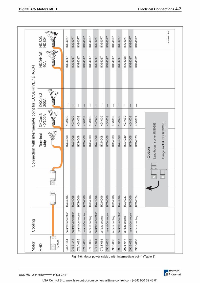
Digital AC- Motors MHD Electrical Connections 4-7
DOK-MOTOR*-MHD********-PR03-EN-P
cabl
e068
1z.fh
7
INS
0681
4 3 2 1
7 6 5 4 3
4 3 2 1
7 6 5 4 3 2 1
4 3 2 1
Mot
or C
oolin
gC
onne
ctio
n w
ith in
term
edia
te p
oint
for
EC
OD
RIV
E /
DIA
X04
MH
DTe
rmin
alD
KC
xx.3
DK
Cxx
.3H
DD
/HD
SH
DS
03st
rip40
/100
A20
0A40
AH
DS
04
041A
-144
natu
ral C
onve
ctio
nIK
G40
06IK
G40
08IK
G40
09--
-IK
G40
17IK
G40
77
041B
-144
natu
ral C
onve
ctio
nIK
G40
06IK
G40
08IK
G40
09--
-IK
G40
17IK
G40
77
071A
-035
natu
ral C
onve
ctio
nIK
G40
06IK
G40
08IK
G40
09--
-IK
G40
17IK
G40
77
071B
-035
natu
ral C
onve
ctio
nIK
G40
06IK
G40
08IK
G40
09--
-IK
G40
17IK
G40
77
071B
-035
surf
ace
cool
ing
IKG
4006
IKG
4008
IKG
4009
---
IKG
4017
IKG
4077
071B
-061
natu
ral C
onve
ctio
nIK
G40
06IK
G40
08IK
G40
09--
-IK
G40
17IK
G40
77
071B
-061
surf
ace
cool
ing
IKG
4006
IKG
4008
IKG
4009
---
IKG
4017
IKG
4077
090B
-035
natu
ral C
onve
ctio
nIK
G40
06IK
G40
08IK
G40
09--
-IK
G40
17IK
G40
77
090B
-035
surf
ace
cool
ing
IKG
4006
IKG
4008
IKG
4009
---
IKG
4017
IKG
4077
090B
-047
natu
ral C
onve
ctio
nIK
G40
06IK
G40
08IK
G40
09--
-IK
G40
17IK
G40
77
090B
-047
surf
ace
cool
ing
IKG
4027
IKG
4029
IKG
4039
---
IKG
4028
IKG
4077
090B
-058
natu
ral C
onve
ctio
nIK
G40
06IK
G40
08IK
G40
09--
-IK
G40
17IK
G40
77
090B
-058
surf
ace
cool
ing
IKG
4074
IKG
4073
IKG
4071
---
IKG
4072
IKG
4077
Opt
ion
Lead
thou
gh s
ocke
t IN
S06
85
Fla
nge
sock
et IN
S06
83/C
03
Fig. 4-6: Motor power cable „ with intermediate point“ (Table 1)
LSA Control S.L. www.lsa-control.com [email protected] (+34) 960 62 43 01
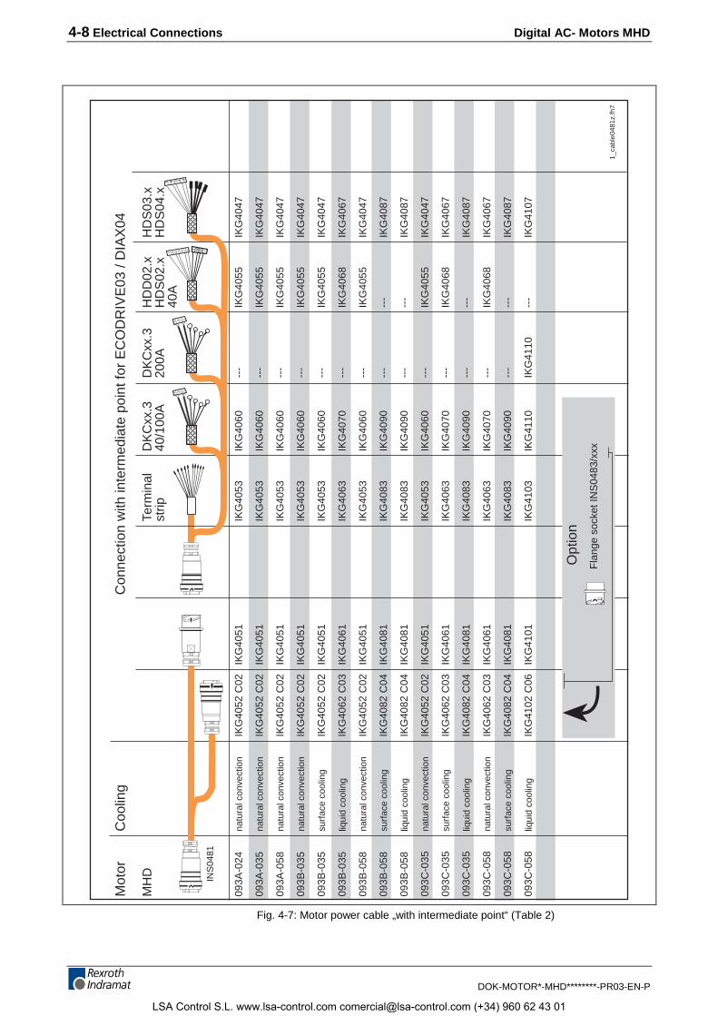
4-8 Electrical Connections Digital AC- Motors MHD
DOK-MOTOR*-MHD********-PR03-EN-P
1_ca
ble0
481z
.fh7
INS
0481
4 3 2 1
7 6 5 4 3
4 3 2 1
7 6 5 4 3 2 1
4 3 2 1
Mot
or
Coo
ling
Con
nect
ion
with
inte
rmed
iate
poi
nt fo
r E
CO
DR
IVE
03 /
DIA
X04
MH
DTe
rmin
alD
KC
xx.3
DK
Cxx
.3H
DD
02.x
HD
S03
.xst
rip40
/100
A20
0AH
DS
02.x
HD
S04
.x
40A
093A
-024
natu
ral c
onve
ctio
nIK
G40
52 C
02IK
G40
51IK
G40
53IK
G40
60--
-IK
G40
55IK
G40
47
093A
-035
natu
ral c
onve
ctio
nIK
G40
52 C
02IK
G40
51IK
G40
53IK
G40
60--
-IK
G40
55IK
G40
47
093A
-058
natu
ral c
onve
ctio
nIK
G40
52 C
02IK
G40
51IK
G40
53IK
G40
60--
-IK
G40
55IK
G40
47
093B
-035
natu
ral c
onve
ctio
nIK
G40
52 C
02IK
G40
51IK
G40
53IK
G40
60--
-IK
G40
55IK
G40
47
093B
-035
surf
ace
cool
ing
IKG
4052
C02
IKG
4051
IKG
4053
IKG
4060
---
IKG
4055
IKG
4047
093B
-035
liqui
d co
olin
gIK
G40
62 C
03IK
G40
61IK
G40
63IK
G40
70--
-IK
G40
68IK
G40
67
093B
-058
natu
ral c
onve
ctio
nIK
G40
52 C
02IK
G40
51IK
G40
53IK
G40
60--
-IK
G40
55IK
G40
47
093B
-058
surf
ace
cool
ing
IKG
4082
C04
IKG
4081
IKG
4083
IKG
4090
---
---
IKG
4087
093B
-058
liqui
d co
olin
gIK
G40
82 C
04IK
G40
81IK
G40
83IK
G40
90--
---
-IK
G40
87
093C
-035
natu
ral c
onve
ctio
nIK
G40
52 C
02IK
G40
51IK
G40
53IK
G40
60--
-IK
G40
55IK
G40
47
093C
-035
surf
ace
cool
ing
IKG
4062
C03
IKG
4061
IKG
4063
IKG
4070
---
IKG
4068
IKG
4067
093C
-035
liqui
d co
olin
gIK
G40
82 C
04IK
G40
81IK
G40
83IK
G40
90--
---
-IK
G40
87
093C
-058
natu
ral c
onve
ctio
nIK
G40
62 C
03IK
G40
61IK
G40
63IK
G40
70--
-IK
G40
68IK
G40
67
093C
-058
surf
ace
cool
ing
IKG
4082
C04
IKG
4081
IKG
4083
IKG
4090
---
---
IKG
4087
093C
-058
liqui
d co
olin
gIK
G41
02 C
06IK
G41
01IK
G41
03IK
G41
10IK
G41
10--
-IK
G41
07
Opt
ion
Fla
nge
sock
et IN
S04
83/x
xx
Fig. 4-7: Motor power cable „with intermediate point“ (Table 2)
LSA Control S.L. www.lsa-control.com [email protected] (+34) 960 62 43 01
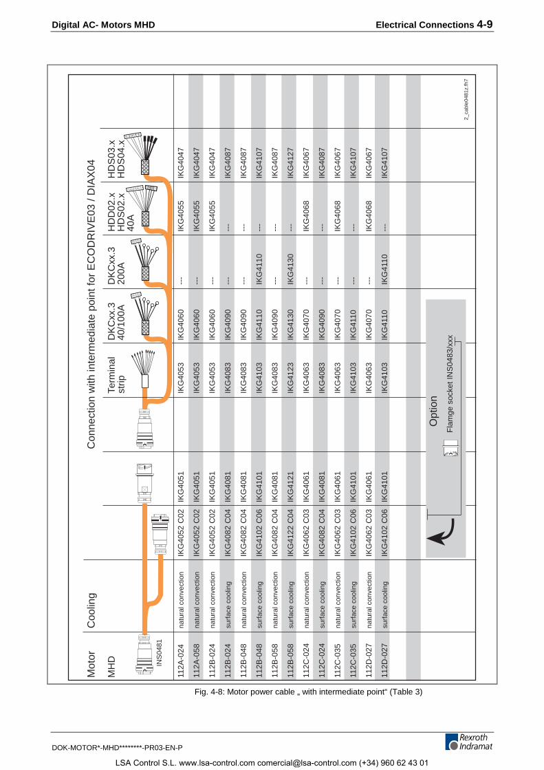
Digital AC- Motors MHD Electrical Connections 4-9
DOK-MOTOR*-MHD********-PR03-EN-P
2_ca
ble0
481z
.fh7
INS
0481
4 3 2 1
7 6 5 4 3
4 3 2 1
7 6 5 4 3 2 1
4 3 2 1
Mot
or
Coo
ling
Con
nect
ion
with
inte
rmed
iate
poi
nt fo
r E
CO
DR
IVE
03 /
DIA
X04
MH
DTe
rmin
al
DK
Cxx
.3D
KC
xx.3
HD
D02
.xH
DS
03.x
strip
40/1
00A
200A
HD
S02
.xH
DS
04.x
40
A
112A
-024
natu
ral c
onve
ctio
n IK
G40
52 C
02IK
G40
51IK
G40
53IK
G40
60--
-IK
G40
55IK
G40
47
112A
-058
natu
ral c
onve
ctio
nIK
G40
52 C
02IK
G40
51IK
G40
53IK
G40
60--
-IK
G40
55IK
G40
47
112B
-024
natu
ral c
onve
ctio
nIK
G40
52 C
02IK
G40
51IK
G40
53IK
G40
60--
-IK
G40
55IK
G40
47
112B
-024
surf
ace
cool
ing
IKG
4082
C04
IKG
4081
IKG
4083
IKG
4090
---
---
IKG
4087
112B
-048
natu
ral c
onve
ctio
nIK
G40
82 C
04IK
G40
81IK
G40
83IK
G40
90--
---
-IK
G40
87
112B
-048
surf
ace
cool
ing
IKG
4102
C06
IKG
4101
IKG
4103
IKG
4110
IKG
4110
---
IKG
4107
112B
-058
natu
ral c
onve
ctio
nIK
G40
82 C
04IK
G40
81IK
G40
83IK
G40
90--
---
-IK
G40
87
11
2B-0
58su
rfac
e co
olin
gIK
G41
22 C
04IK
G41
21IK
G41
23IK
G41
30IK
G41
30--
-IK
G41
27
112C
-024
natu
ral c
onve
ctio
nIK
G40
62 C
03IK
G40
61IK
G40
63IK
G40
70--
-IK
G40
68IK
G40
67
112C
-024
surf
ace
cool
ing
IKG
4082
C04
IKG
4081
IKG
4083
IKG
4090
---
---
IKG
4087
112C
-035
natu
ral c
onve
ctio
nIK
G40
62 C
03IK
G40
61IK
G40
63IK
G40
70--
-IK
G40
68IK
G40
67
112C
-035
surf
ace
cool
ing
IKG
4102
C06
IKG
4101
IKG
4103
IKG
4110
---
---
IKG
4107
112D
-027
natu
ral c
onve
ctio
nIK
G40
62 C
03IK
G40
61IK
G40
63IK
G40
70--
-IK
G40
68IK
G40
67
112D
-027
surf
ace
cool
ing
IKG
4102
C06
IKG
4101
IKG
4103
IKG
4110
IKG
4110
---
IKG
4107
Opt
ion
Fla
mge
soc
ket I
NS
0483
/xxx
Fig. 4-8: Motor power cable „ with intermediate point“ (Table 3)
LSA Control S.L. www.lsa-control.com [email protected] (+34) 960 62 43 01
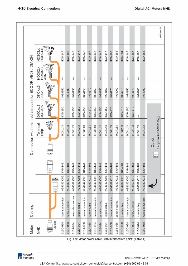
4-10 Electrical Connections Digital AC- Motors MHD
DOK-MOTOR*-MHD********-PR03-EN-P
1_ca
ble0
381.
fh7
INS
0381
4 3 2 1
7 6 5 4 3
4 3 2 1
7 6 5 4 3 2 1
4 3 2 1
Mot
or
Coo
ling
Con
nect
ion
with
inte
rmed
iate
poi
nt fo
r E
CO
DR
IVE
03 /
DIA
X04
MH
DTe
rmin
alD
KC
xx.3
DK
Cxx
.3H
DD
02.x
HD
S03
.xS
trip
40/1
00A
200A
HD
S02
.xH
DS
04.x
40
A
112C
-058
natu
ral c
onve
ctio
nIK
G41
42 C
06IK
G41
41IK
G41
43IK
G41
50IK
G41
50--
-IK
G41
47
112C
-058
surf
ace
cool
ing
IKG
4182
C16
IKG
4181
IKG
4183
---
IKG
4200
---
IKG
4186
115A
-024
nnat
ural
con
vect
ion
IKG
4142
C06
IKG
4141
IKG
4143
IKG
4150
IKG
4150
---
IKG
4147
115A
-024
liqui
d co
olin
gIK
G41
42 C
06IK
G41
41IK
G41
43IK
G41
50IK
G41
50--
-IK
G41
47
115A
-058
natu
ral c
onve
ctio
nIK
G41
42 C
06IK
G41
41IK
G41
43IK
G41
50IK
G41
50--
-IK
G41
47
115A
-058
liqui
d co
olin
gIK
G41
62 C
10IK
G41
61IK
G41
63IK
G41
70IK
G41
70--
-IK
G41
67
115B
-024
natu
ral c
onve
ctio
nIK
G41
42 C
06IK
G41
41IK
G41
43IK
G41
50IK
G41
50--
-IK
G41
47
115B
-024
surf
ace
cool
ing
IKG
4142
C06
IKG
4141
IKG
4143
IKG
4150
IKG
4150
---
IKG
4147
115B
-024
liqui
d co
olin
gIK
G41
42 C
06IK
G41
41IK
G41
43IK
G41
50IK
G41
50--
-IK
G41
47
115B
-058
natu
ral c
onve
ctio
nIK
G41
62 C
10IK
G41
61IK
G41
63IK
G41
70IK
G41
70--
-IK
G41
67
115B
-058
surf
ace
cool
ing
IKG
4182
C16
IKG
4181
IKG
4183
---
IKG
4200
---
IKG
4186
115B
-058
liqui
d co
olin
gIK
G42
02 C
25IK
G42
01IK
G42
03IK
G42
10IK
G42
10--
-IK
G42
04
115C
-024
natu
ral c
onve
ctio
nIK
G41
42 C
06IK
G41
41IK
G41
43IK
G41
50IK
G41
50--
-IK
G41
47
115C
-024
surf
ace
cool
ing
IKG
4162
C10
IKG
4161
IKG
4163
IKG
4170
IKG
4170
---
IKG
4167
115C
-024
liqui
d co
olin
gIK
G41
82 C
16IK
G41
81IK
G41
83--
-IK
G42
00--
-IK
G41
86
115C
-058
natu
ral c
onve
ctio
nIK
G41
82 C
16IK
G41
81IK
G41
83--
-IK
G42
00--
-IK
G41
86
Opt
ion
Fla
nge
sock
et IN
S03
83/x
xx
Fig. 4-9: Motor power cable „with intermediate point“ (Table 4)
LSA Control S.L. www.lsa-control.com [email protected] (+34) 960 62 43 01
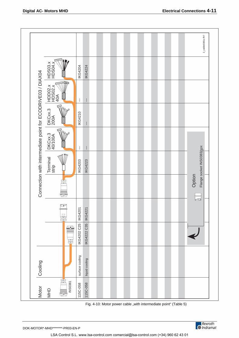
Digital AC- Motors MHD Electrical Connections 4-11
DOK-MOTOR*-MHD********-PR03-EN-P
2_ca
ble0
381z
.fh7
INS
0381
4 3 2 1
7 6 5 4 3
4 3 2 1
7 6 5 4 3 2 1
4 3 2 1
Mot
or
Coo
ling
Con
nect
ion
with
inte
rmed
iate
poi
nt fo
r E
CO
DR
IVE
03 /
DIA
X04
MH
DTe
rmin
alD
KC
xx.3
DK
Cxx
.3H
DD
02.x
HD
S03
.xst
rip40
/100
A20
0AH
DS
02.x
HD
S04
.x
40A
115C
-058
surf
ace
cool
ing
IKG
4202
C25
IKG
4201
IKG
4203
---
IKG
4210
---
IKG
4204
115C
-058
liqui
d co
olin
gIK
G42
22 C
35IK
G42
21IK
G42
23--
---
---
-IK
G42
24
Opt
ion
Fla
nge
sock
et IN
S03
83/x
xx
Fig. 4-10: Motor power cable „with intermediate point“ (Table 5)
LSA Control S.L. www.lsa-control.com [email protected] (+34) 960 62 43 01
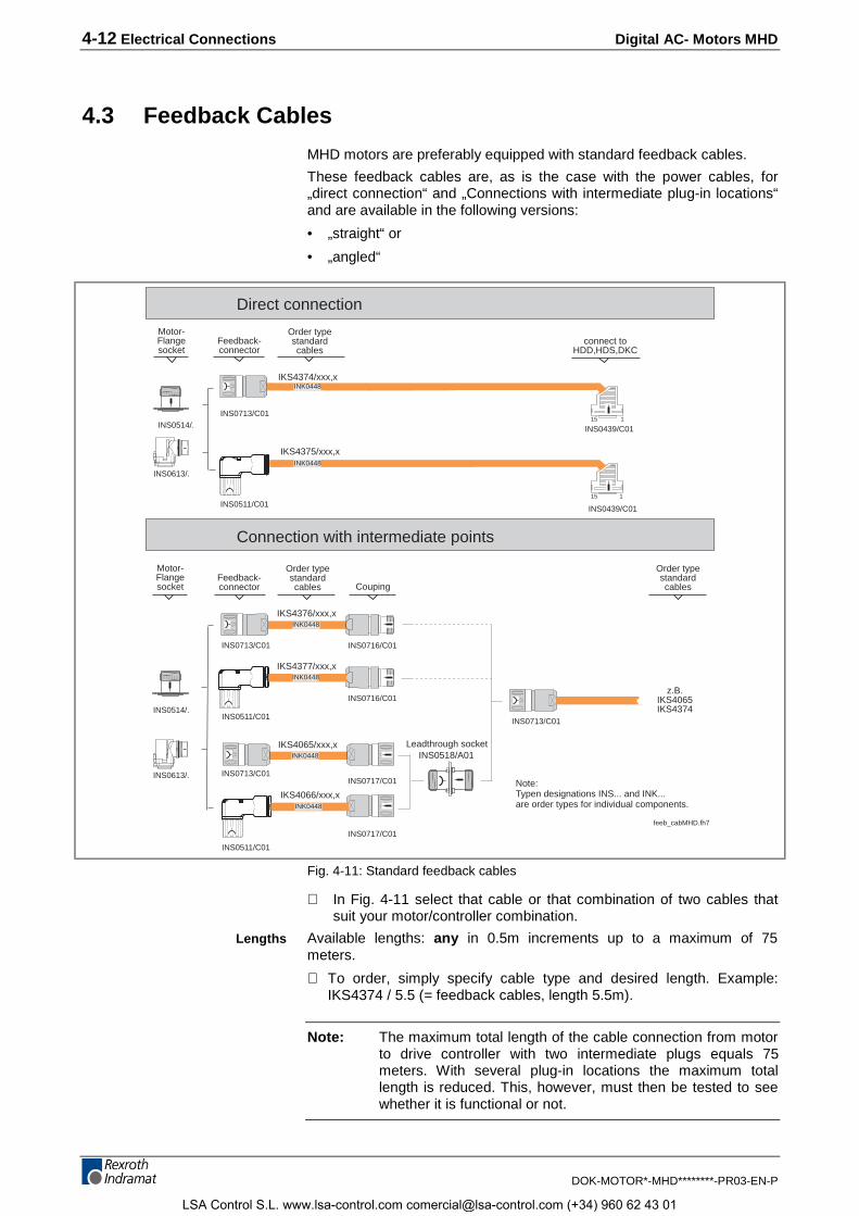
4-12 Electrical Connections Digital AC- Motors MHD
DOK-MOTOR*-MHD********-PR03-EN-P
4.3 Feedback Cables
MHD motors are preferably equipped with standard feedback cables.
These feedback cables are, as is the case with the power cables, for„direct connection“ and „Connections with intermediate plug-in locations“and are available in the following versions:
• „straight“ or
• „angled“
Feedback-connector
connect toHDD,HDS,DKC
IKS4374/xxx,x
z.B.IKS4065IKS4374
Direct connection
Connection with intermediate points
IKS4376/xxx,x
15 1INS0713/C01
INS0716/C01
INS0713/C01
INS0514/.
INS0713/C01
INS0713/C01
INS0439/C01
Couping
Motor-Flangesocket
Order typestandardcables
Order typestandardcables
Order typestandardcables
Feedback-connector
Motor-Flangesocket
INS0613/.
INS0514/.
INS0613/.
INK0448
IKS4375/xxx,x
15 1INS0511/C01 INS0439/C01
INK0448
INS0511/C01
feeb_cabMHD.fh7
Note:Typen designations INS... and INK...are order types for individual components.
INS0518/A01IKS4065/xxx,x Leadthrough socket
INS0717/C01
INK0448
IKS4377/xxx,x
INS0716/C01
INK0448
IKS4066/xxx,x
INS0511/C01
INS0717/C01
INK0448
INK0448
Fig. 4-11: Standard feedback cables
⇒ In Fig. 4-11 select that cable or that combination of two cables thatsuit your motor/controller combination.
Available lengths: any in 0.5m increments up to a maximum of 75meters.
⇒ To order, simply specify cable type and desired length. Example:IKS4374 / 5.5 (= feedback cables, length 5.5m).
Note: The maximum total length of the cable connection from motorto drive controller with two intermediate plugs equals 75meters. With several plug-in locations the maximum totallength is reduced. This, however, must then be tested to seewhether it is functional or not.
Lengths
LSA Control S.L. www.lsa-control.com [email protected] (+34) 960 62 43 01
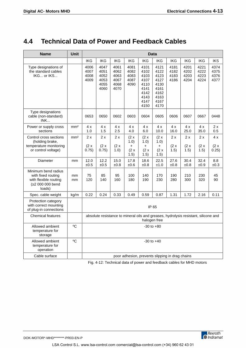
Digital AC- Motors MHD Electrical Connections 4-13
DOK-MOTOR*-MHD********-PR03-EN-P
4.4 Technical Data of Power and Feedback Cables
Name Unit Data
IKG IKG IKG IKG IKG IKG IKG IKG IKG IKS
Type designations ofthe standard cables
IKG... or IKS...
4006400740084009
404740514052405340554060
406140624063406740684070
40814082408340874090
4101410241034107411041414142414341474150
4121412241234127413041614162416341674170
4181418241834186
4201420242034204
4221422242234224
4374437543764377
Type designationscable (non-standard)
INK...0653 0650 0602 0603 0604 0605 0606 0607 0667 0448
Power or supply crosssections
mm² 4 x1.0
4 x1.5
4 x2.5
4 x4.0
4 x6.0
4 x10.0
4 x16.0
4 x25.0
4 x35.0
2 x0.5
Control cross sections(holding brake,
temperature monitoringor control voltage)
mm² 2 x
(2 x0.75)
2 x
(2 x0.75)
2 x
(2 x1.0)
(2 x1.0)
+ (2 x1.5)
(2 x1.0)
+ (2 x1.5)
(2 x1.0)
+ (2 x1.5)
2 x
(2 x1.5)
2 x
(2 x1.5)
2 x
(2 x1.5)
4 x
(2 x0.25)
Diameter mm 12.0±0.5
12.2±0.5
15.0±0.8
17.8±0.6
18.6±0.8
22.5±1.0
27.6±0.8
30.4±0.8
32.4±0.9
8.8±0.3
Minimum bend radiuswith fixed routing
with flexible routing(≥2 000 000 bend
loads)
mmmm
75120
85140
95160
100180
140190
170230
190280
210300
230320
4590
Spec. cable weight kg/m 0.22 0.24 0.33 0.49 0.59 0.87 1.31 1.72 2.16 0.11
Protection categorywith correct mountingof plug-in connections
IP 65
Chemical features absolute resistance to mineral oils and greases, hydrolysis resistant, silicone andhalogen free
Allowed ambienttemperature for
storage
ºC -30 to +80
Allowed ambienttemperature for
operation
ºC -30 to +40
Cable surface poor adhesion, prevents slipping in drag chains
Fig. 4-12: Technical data of power and feedback cables for MHD motors
LSA Control S.L. www.lsa-control.com [email protected] (+34) 960 62 43 01
4-14 Electrical Connections Digital AC- Motors MHD
DOK-MOTOR*-MHD********-PR03-EN-P
4.5 Individual Parts
Note: The user can make INDRAMAT cables himself. The partsneeded for this are listed in the document „Connectionaccessories for INDRAMAT drives”, doc. no. 209-0050-4399-XX. If INDRAMAT cables are not used, it is still necessary touse INDRAMAT connectors. When selecting the plug-inconnections note cable cross sections.
Note: Guarantee forfeited!
• If non-INDRAMAT cables are used, then the guarantee for the entiresystem is forfeited, e.g., EMC guidelines and similar. It isrecommended and advisable to use INDRAMAT cables only!
⇒ Use the following list to determine which motor power connector andcable cross sections are needed for individual MHD motors.
⇒ Motor power connections are available in crimped or solderedversions.
⇒ With motor power connectors, there must be strain reliefs that matchthe conduit threads in the cables used. The dimensions of the relevantconduit thread connectors are listed in sections 6 through 11, section„Dimensions“.
Selecting power connectors andcables
LSA Control S.L. www.lsa-control.com [email protected] (+34) 960 62 43 01
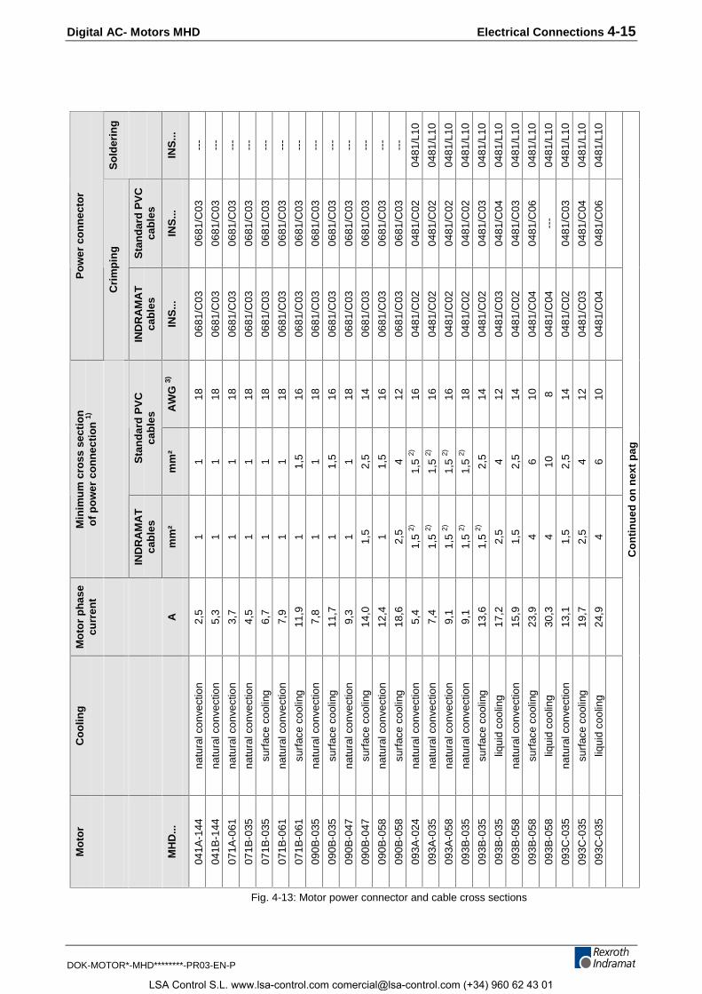
Digital AC- Motors MHD Electrical Connections 4-15
DOK-MOTOR*-MHD********-PR03-EN-P
So
lder
ing
INS
...
---
---
---
---
---
---
---
---
---
---
---
---
---
0481
/L10
0481
/L10
0481
/L10
0481
/L10
0481
/L10
0481
/L10
0481
/L10
0481
/L10
0481
/L10
0481
/L10
0481
/L10
0481
/L10
Sta
nd
ard
PV
Cca
ble
s
INS
...
0681
/C03
0681
/C03
0681
/C03
0681
/C03
0681
/C03
0681
/C03
0681
/C03
0681
/C03
0681
/C03
0681
/C03
0681
/C03
0681
/C03
0681
/C03
0481
/C02
0481
/C02
0481
/C02
0481
/C02
0481
/C03
0481
/C04
0481
/C03
0481
/C06
---
0481
/C03
0481
/C04
0481
/C06
Po
wer
co
nn
ecto
r
Cri
mp
ing
IND
RA
MA
Tca
ble
s
INS
...
0681
/C03
0681
/C03
0681
/C03
0681
/C03
0681
/C03
0681
/C03
0681
/C03
0681
/C03
0681
/C03
0681
/C03
0681
/C03
0681
/C03
0681
/C03
0481
/C02
0481
/C02
0481
/C02
0481
/C02
0481
/C02
0481
/C03
0481
/C02
0481
/C04
0481
/C04
0481
/C02
0481
/C03
0481
/C04
AW
G 3)
18 18 18 18 18 18 16 18 16 18 14 16 12 16 16 16 18 14 12 14 10 8 14 12 10
Sta
nd
ard
PV
Cca
ble
s
mm
²
1 1 1 1 1 1 1,5 1 1,5 1 2,5
1,5 4
1,5
2)
1,5
2)
1,5
2)
1,5
2)
2,5 4 2,5 6 10 2,5 4 6
Min
imum
cro
ss s
ectio
nof
pow
er c
onne
ctio
n 1)
IND
RA
MA
Tca
bles
mm
²
1 1 1 1 1 1 1 1 1 1 1,5 1 2,5
1,5
2)
1,5
2)
1,5
2)
1,5
2)
1,5
2)
2,5
1,5 4 4 1,5
2,5 4
Mot
or p
hase
curr
ent
A 2,5
5,3
3,7
4,5
6,7
7,9
11,9
7,8
11,7
9,3
14,0
12,4
18,6
5,4
7,4
9,1
9,1
13,6
17,2
15,9
23,9
30,3
13,1
19,7
24,9
Coo
ling
natu
ral c
onve
ctio
n
natu
ral c
onve
ctio
n
natu
ral c
onve
ctio
n
natu
ral c
onve
ctio
n
surf
ace
cool
ing
natu
ral c
onve
ctio
n
surf
ace
cool
ing
natu
ral c
onve
ctio
n
surf
ace
cool
ing
natu
ral c
onve
ctio
n
surf
ace
cool
ing
natu
ral c
onve
ctio
n
surf
ace
cool
ing
natu
ral c
onve
ctio
n
natu
ral c
onve
ctio
n
natu
ral c
onve
ctio
n
natu
ral c
onve
ctio
n
surf
ace
cool
ing
liqui
d co
olin
g
natu
ral c
onve
ctio
n
surf
ace
cool
ing
liqui
d co
olin
g
natu
ral c
onve
ctio
n
surf
ace
cool
ing
liqui
d co
olin
g
Mot
or
MH
D...
041A
-144
041B
-144
071A
-061
071B
-035
071B
-035
071B
-061
071B
-061
090B
-035
090B
-035
090B
-047
090B
-047
090B
-058
090B
-058
093A
-024
093A
-035
093A
-058
093B
-035
093B
-035
093B
-035
093B
-058
093B
-058
093B
-058
093C
-035
093C
-035
093C
-035
Con
tinue
d on
nex
t pag
Fig. 4-13: Motor power connector and cable cross sections
LSA Control S.L. www.lsa-control.com [email protected] (+34) 960 62 43 01
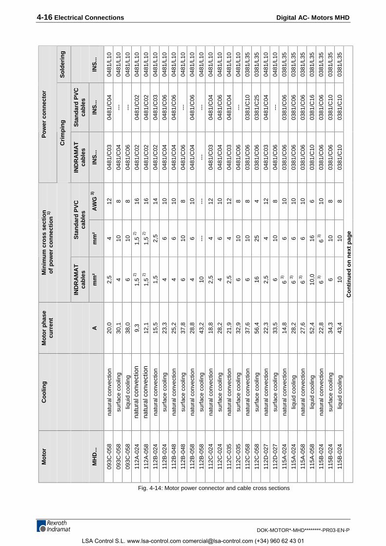
4-16 Electrical Connections Digital AC- Motors MHD
DOK-MOTOR*-MHD********-PR03-EN-P
So
lder
ing
INS
...
0481
/L10
0481
/L10
0481
/L10
0481
/L10
0481
/L10
0481
/L10
0481
/L10
0481
/L10
0481
/L10
0481
/L10
0481
/L10
0481
/L10
0481
/L10
0481
/L10
0481
/L10
0381
/L35
0381
/L35
0481
/L10
0481
/L10
0381
/L35
0381
/L35
0381
/L35
0381
/L35
0381
/L35
0381
/L35
0381
/L35
Sta
nd
ard
PV
Cca
ble
s
INS
...
0481
/C04
---
---
0481
/C02
0481
/C02
0481
/C03
0481
/C06
0481
/C06
---
0481
/C06
---
0481
/C04
0481
/C06
0481
/C04
---
0381
/C10
0381
/C25
0481
/C04
---
0381
/C06
0381
/C06
0381
/C06
0381
/C16
0381
/C06
0381
/C10
0381
/C10
Po
wer
co
nn
ecto
r
Cri
mp
ing
IND
RA
MA
Tca
ble
s
INS
...
0481
/C03
0481
/C04
0481
/C06
0481
/C02
0481
/C02
0481
/C02
0481
/C04
0481
/C04
0481
/C06
0481
/C04
---
0481
/C03
0481
/C04
0481
/C03
0481
/C06
0381
/C06
0381
/C06
0481
/C03
0481
/C06
0381
/C06
0381
/C06
0381
/C06
0381
/C10
0381
/C06
0381
/C06
0381
/C10
AW
G 3)
12 8 8 16 16 14 10 10 8 10 ---
12 10 12 8 8 4 12 8 10 10 10 6 10 8 8
Sta
nd
ard
PV
Cca
ble
s
mm
²
4 10 10 1,5
2)
1,5
2)
2,5 6 6 10 6 --- 4 6 4 10 10 25 4 10 6 6 6 16 6 3)
10 10
Min
imum
cro
ss s
ectio
nof
pow
er c
onne
ctio
n 1)
IND
RA
MA
Tca
bles
mm
²
2,5 4 6
1,5
2)
1,5
2)
1,5 4 4 6 4 10 2,5 4 2,5 6 6 16 2,5 6 6 3)
6 3)
6 3)
10,0
6 3) 6 10
Mot
or p
hase
curr
ent
A
20,0
30,1
38,0
9,3
12,1
15,5
23,3
25,2
37,8
28,8
43,2
18,8
28,2
21,9
32,9
37,6
56,4
22,3
33,5
14,8
28,2
27,6
52,4
22,8
34,3
43,4
Coo
ling
natu
ral c
onve
ctio
n
surf
ace
cool
ing
liqui
d co
olin
g
natu
ral c
onve
ctio
nna
tura
l con
vect
ion
natu
ral c
onve
ctio
n
surf
ace
cool
ing
natu
ral c
onve
ctio
n
surf
ace
cool
ing
natu
ral c
onve
ctio
n
surf
ace
cool
ing
natu
ral c
onve
ctio
n
surf
ace
cool
ing
natu
ral c
onve
ctio
n
surf
ace
cool
ing
natu
ral c
onve
ctio
n
surf
ace
cool
ing
natu
ral c
onve
ctio
n
surf
ace
cool
ing
natu
ral c
onve
ctio
n
liqui
d co
olin
g
natu
ral c
onve
ctio
n
liqui
d co
olin
g
natu
ral c
onve
ctio
n
surf
ace
cool
ing
liqui
d co
olin
g
Mot
or
MH
D...
093C
-058
093C
-058
093C
-058
112A
-024
112A
-058
112B
-024
112B
-024
112B
-048
112B
-048
112B
-058
112B
-058
112C
-024
112C
-024
112C
-035
112C
-035
112C
-058
112C
-058
112D
-027
112D
-027
115A
-024
115A
-024
115A
-058
115A
-058
115B
-024
115B
-024
115B
-024
Con
tinue
d on
nex
t pag
e
Fig. 4-14: Motor power connector and cable cross sections
LSA Control S.L. www.lsa-control.com [email protected] (+34) 960 62 43 01
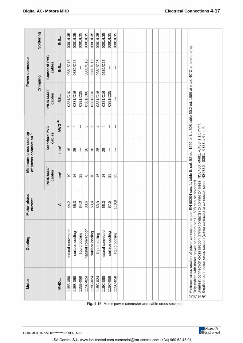
Digital AC- Motors MHD Electrical Connections 4-17
DOK-MOTOR*-MHD********-PR03-EN-P
So
lder
ing
INS
...
0381
/L35
0381
/L35
0381
/L35
0381
/L35
0381
/L35
0381
/L35
0381
/L35
0381
/L35
0381
/L35
Sta
nd
ard
PV
Cca
ble
s
INS
...
0381
/C16
0381
/C25
---
0381
/C10
0381
/C16
0381
/C25
0381
/C25
---
---
Po
wer
co
nn
ecto
r
Cri
mp
ing
IND
RA
MA
Tca
ble
s
INS
...
0381
/C10
0381
/C16
0381
/C25
0381
/C06
0381
/C10
0381
/C16
0381
/C16
0381
/C25
---
AW
G 3)
6 4 --- 8 6 4 4 ---
---
Sta
nd
ard
PV
Cca
ble
s
mm
²
16 25 ---
10 16 25 25 ---
---
Min
imum
cro
ss s
ectio
nof
pow
er c
onne
ctio
n 1)
IND
RA
MA
Tca
bles
mm
²
10 16 25 6 10 16 16 25 35
Mot
or p
hase
curr
ent
A
44,2
66,3
84,0
33,6
50,4
63,9
58,3
87,5
110,
9
Coo
ling
natu
ral c
onve
ctio
n
surf
ace
cool
ing
liqui
d co
olin
g
natu
ral c
onve
ctio
n
surf
ace
cool
ing
liqui
d co
olin
g
natu
ral c
onve
ctio
n
surf
ace
cool
ing
liqui
d co
olin
g
Mot
or
MH
D...
115B
-058
115B
-058
115B
-058
115C
-024
115C
-024
115C
-024
115C
-058
115C
-058
115C
-058
1) M
inim
um c
ross
sec
tion
of p
ower
con
nect
ion
as p
er E
N 6
0204
sec
. 1, t
able
5, c
ol. B
2 ed
. 199
2 or
UL
508
tabl
e 50
.2 e
d. 1
989
at m
ax. 4
0°C
am
bien
t tem
p.2)
Onl
y ca
bles
with
mot
or p
ower
con
nect
ors
per
UL
508
can
be s
olde
red.
3) S
mal
lest
con
nect
ion
cros
s se
ctio
n (c
rimp
cont
acts
) to
con
nect
or s
izes
INS
0480
, -04
81, -
0483
is 1
,5 m
m².
4) S
mal
lest
con
nect
ion
cros
s se
ctio
n (c
rimp
cont
acts
) to
con
nect
or s
izes
INS
0380
, -03
81, -
0383
is 6
mm
².
Fig. 4-15: Motor power connector and cable cross sections
LSA Control S.L. www.lsa-control.com [email protected] (+34) 960 62 43 01
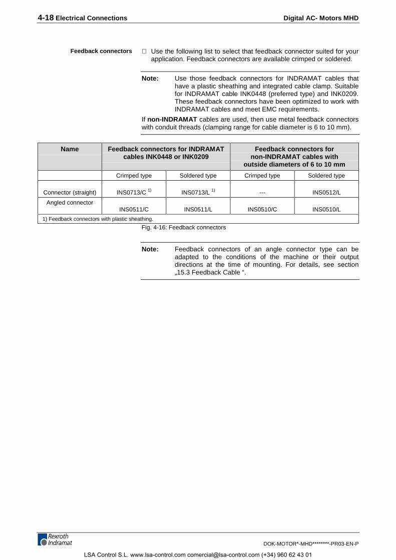
4-18 Electrical Connections Digital AC- Motors MHD
DOK-MOTOR*-MHD********-PR03-EN-P
⇒ Use the following list to select that feedback connector suited for yourapplication. Feedback connectors are available crimped or soldered.
Note: Use those feedback connectors for INDRAMAT cables thathave a plastic sheathing and integrated cable clamp. Suitablefor INDRAMAT cable INK0448 (preferred type) and INK0209.These feedback connectors have been optimized to work withINDRAMAT cables and meet EMC requirements.
If non-INDRAMAT cables are used, then use metal feedback connectorswith conduit threads (clamping range for cable diameter is 6 to 10 mm).
Name Feedback connectors for INDRAMATcables INK0448 or INK0209
Feedback connectors fornon-INDRAMAT cables with
outside diameters of 6 to 10 mm
Crimped type Soldered type Crimped type Soldered type
Connector (straight) INS0713/C 1) INS0713/L 1) --- INS0512/L
Angled connectorINS0511/C INS0511/L INS0510/C INS0510/L
1) Feedback connectors with plastic sheathing.
Fig. 4-16: Feedback connectors
Note: Feedback connectors of an angle connector type can beadapted to the conditions of the machine or their outputdirections at the time of mounting. For details, see section„15.3 Feedback Cable “.
Feedback connectors
LSA Control S.L. www.lsa-control.com [email protected] (+34) 960 62 43 01
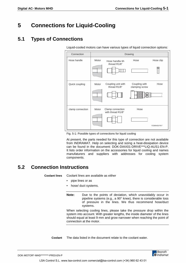
Digital AC- Motors MHD Connections for Liquid-Cooling 5-1
DOK-MOTOR*-MHD********-PR03-EN-P
5 Connections for Liquid-Cooling
5.1 Types of Connections
Liquid-cooled motors can have various types of liquid connection options:
Y03MH81P.fh7
Motor Hose Hose clip
Coupling unit withthread R1/8"
Coupling withclamping screw
Hose
Clamp connectionwith thread R1/8"
Quick coupling Motor
Hose handle
Motorclamp connection Hose
Hose handlw tihthread R1/8"
DrawingConnection
Fig. 5-1: Possible types of connections for liquid cooling
At present, the parts needed for this type of connection are not availablefrom INDRAMAT. Help on selecting and sizing a heat-dissipation devicecan be found in the document: DOK-DIAX01-DRIVE***LIQ-AUS1-EN-P.It lists order information on the accessories for liquid cooling and namesmanufaturers and suppliers with addresses for cooling systemcomponents.
5.2 Connection Instructions
Coolant lines are available as either
• pipe lines or as
• hose/ duct systems.
Note: Due to the points of deviation, which unavoidably occur inpipeline systems (e.g., a 90° knee), there is considerable lossof pressure in the lines. We thus recommend hose/ductsystems.
When selecting cooling lines, please take the pressure drop within thesystem into account. With greater lengths, the inside diameter of the linesshould equal at least 9 mm and grow narrower when reaching the point ofconnection at the motor.
The data listed in the document relate to the coolant water.
Coolant lines
Coolant
LSA Control S.L. www.lsa-control.com [email protected] (+34) 960 62 43 01
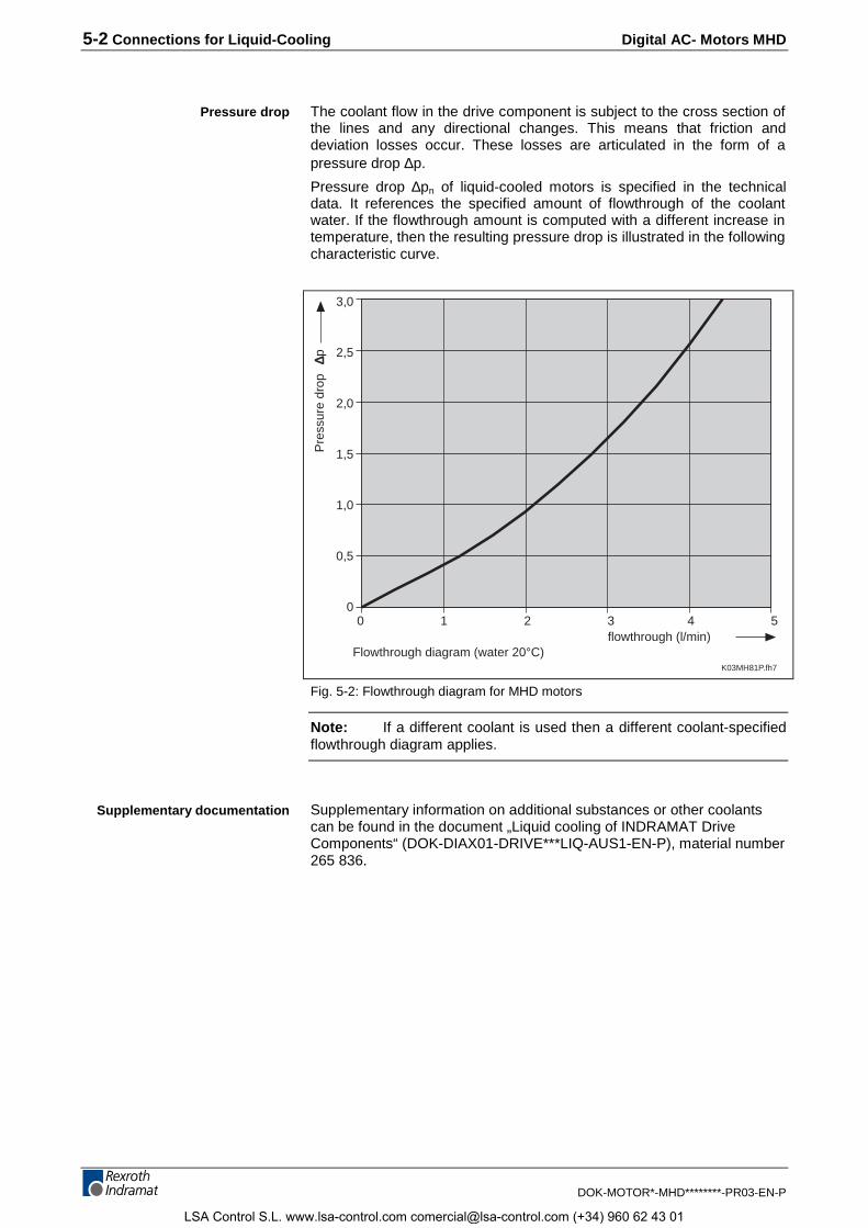
5-2 Connections for Liquid-Cooling Digital AC- Motors MHD
DOK-MOTOR*-MHD********-PR03-EN-P
The coolant flow in the drive component is subject to the cross section ofthe lines and any directional changes. This means that friction anddeviation losses occur. These losses are articulated in the form of apressure drop ∆p.
Pressure drop ∆pn of liquid-cooled motors is specified in the technicaldata. It references the specified amount of flowthrough of the coolantwater. If the flowthrough amount is computed with a different increase intemperature, then the resulting pressure drop is illustrated in the followingcharacteristic curve.
0 1 2 3 4 5
3,0
2,5
2,0
1,5
1,0
0,5
0
flowthrough (l/min)
Pre
ssur
e dr
op
∆p
K03MH81P.fh7
Flowthrough diagram (water 20°C)
Fig. 5-2: Flowthrough diagram for MHD motors
Note: If a different coolant is used then a different coolant-specifiedflowthrough diagram applies.
Supplementary information on additional substances or other coolantscan be found in the document „Liquid cooling of INDRAMAT DriveComponents“ (DOK-DIAX01-DRIVE***LIQ-AUS1-EN-P), material number265 836.
Pressure drop
Supplementary documentation
LSA Control S.L. www.lsa-control.com [email protected] (+34) 960 62 43 01
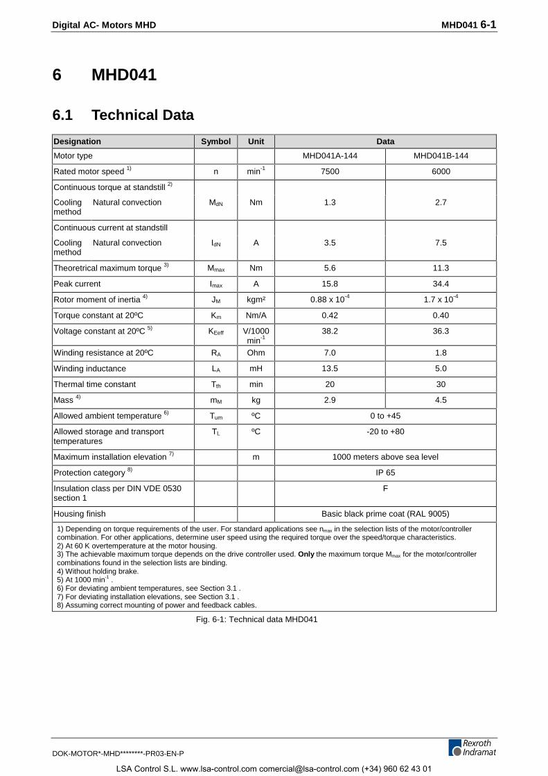
Digital AC- Motors MHD MHD041 6-1
DOK-MOTOR*-MHD********-PR03-EN-P
6 MHD041
6.1 Technical Data
Designation Symbol Unit Data
Motor type MHD041A-144 MHD041B-144
Rated motor speed 1) n min-1 7500 6000
Continuous torque at standstill 2)
Coolingmethod
Natural convection MdN Nm 1.3 2.7
Continuous current at standstill
Coolingmethod
Natural convection IdN A 3.5 7.5
Theoretrical maximum torque 3) Mmax Nm 5.6 11.3
Peak current Imax A 15.8 34.4
Rotor moment of inertia 4) JM kgm² 0.88 x 10⁻⁴ 1.7 x 10⁻⁴
Torque constant at 20ºC Km Nm/A 0.42 0.40
Voltage constant at 20ºC 5) KEeff V/1000min-1
38.2 36.3
Winding resistance at 20ºC RA Ohm 7.0 1.8
Winding inductance LA mH 13.5 5.0
Thermal time constant Tth min 20 30
Mass 4) mM kg 2.9 4.5
Allowed ambient temperature 6) Tum ºC 0 to +45
Allowed storage and transporttemperatures
TL ºC -20 to +80
Maximum installation elevation 7) m 1000 meters above sea level
Protection category 8) IP 65
Insulation class per DIN VDE 0530section 1
F
Housing finish Basic black prime coat (RAL 9005)
1) Depending on torque requirements of the user. For standard applications see nmax in the selection lists of the motor/controllercombination. For other applications, determine user speed using the required torque over the speed/torque characteristics.2) At 60 K overtemperature at the motor housing.3) The achievable maximum torque depends on the drive controller used. Only the maximum torque Mmax for the motor/controllercombinations found in the selection lists are binding.4) Without holding brake.5) At 1000 min-1 .6) For deviating ambient temperatures, see Section 3.1 .7) For deviating installation elevations, see Section 3.1 .8) Assuming correct mounting of power and feedback cables.
Fig. 6-1: Technical data MHD041
LSA Control S.L. www.lsa-control.com [email protected] (+34) 960 62 43 01
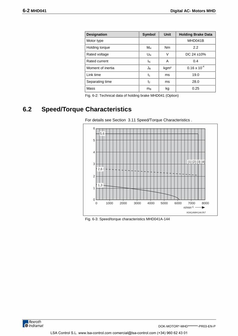
6-2 MHD041 Digital AC- Motors MHD
DOK-MOTOR*-MHD********-PR03-EN-P
Designation Symbol Unit Holding Brake Data
Motor type MHD041B
Holding torque MH Nm 2.2
Rated voltage UN V DC 24 ±10%
Rated current IN A 0.4
Moment of inertia JB kgm² 0.16 x 10⁻⁴
Link time t1 ms 19.0
Separating time t2 ms 28.0
Mass mB kg 0.25
Fig. 6-2: Technical data of holding brake MHD041 (Option)
6.2 Speed/Torque Characteristics
For details see Section 3.11 Speed/Torque Characteristics .
Datum der Messung 98-03-18
K041AMH144.fh7
n/min-11000
02000 3000 4000 5000 60000
2
4
5
7000 8000
1
3
6
5,6
1,3
2,6
[1] [2] [3] [4]
Fig. 6-3: Speed/torque characteristics MHD041A-144
LSA Control S.L. www.lsa-control.com [email protected] (+34) 960 62 43 01
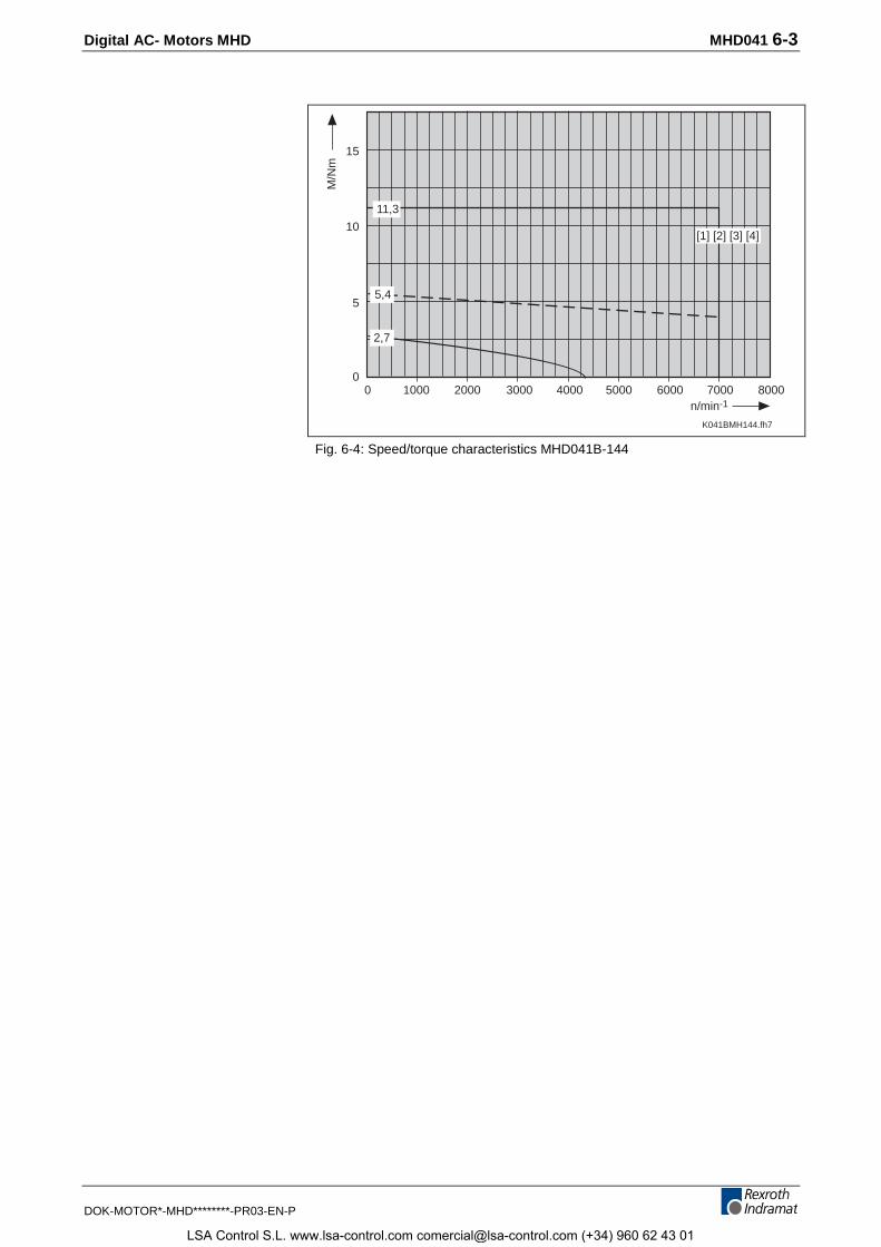
Digital AC- Motors MHD MHD041 6-3
DOK-MOTOR*-MHD********-PR03-EN-P
Datum der Messung 98-03-16
K041BMH144.fh7
n/min-1
M/N
m
10000
2000 3000 4000 5000 60000
5
10
15
7000 8000
11,3
2,7
5,4
[1] [2] [3] [4]
Fig. 6-4: Speed/torque characteristics MHD041B-144
LSA Control S.L. www.lsa-control.com [email protected] (+34) 960 62 43 01
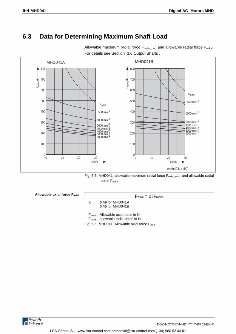
6-4 MHD041 Digital AC- Motors MHD
DOK-MOTOR*-MHD********-PR03-EN-P
6.3 Data for Determining Maximum Shaft Load
Allowable maximum radial force Fradial_max and allowable radial force Fradial
For details see Section 3.6 Output Shafts .
10 20 30x/mm
200
400
600
nmittel
500 min-1
1000 min-1
2000 min-13000 min-14000 min-1
6000 min-1
Fra
dia
l/N
5000 min-1
300
500
700
800
100
00 10 20 30
x/mm
200
400
600nmittel
500 min-1
1000 min-1
2000 min-13000 min-14000 min-1
6000 min-1
Fra
dia
l/N
5000 min-1
300
500
700
800
100
00
MHD041A MHD041B
wmhd041x.fh7
Fig. 6-5: MHD041: allowable maximum radial force Fradial_max and allowable radialforce Fradial
F x Faxial radial= ⋅x: 0.49 for MHD041A
0.45 for MHD041B
Faxial: Allowable axial force in NFradial: allowable radial force in N
Fig. 6-6: MHD041: Allowable axial force Faxial
Allowable axial force Faxial
LSA Control S.L. www.lsa-control.com [email protected] (+34) 960 62 43 01
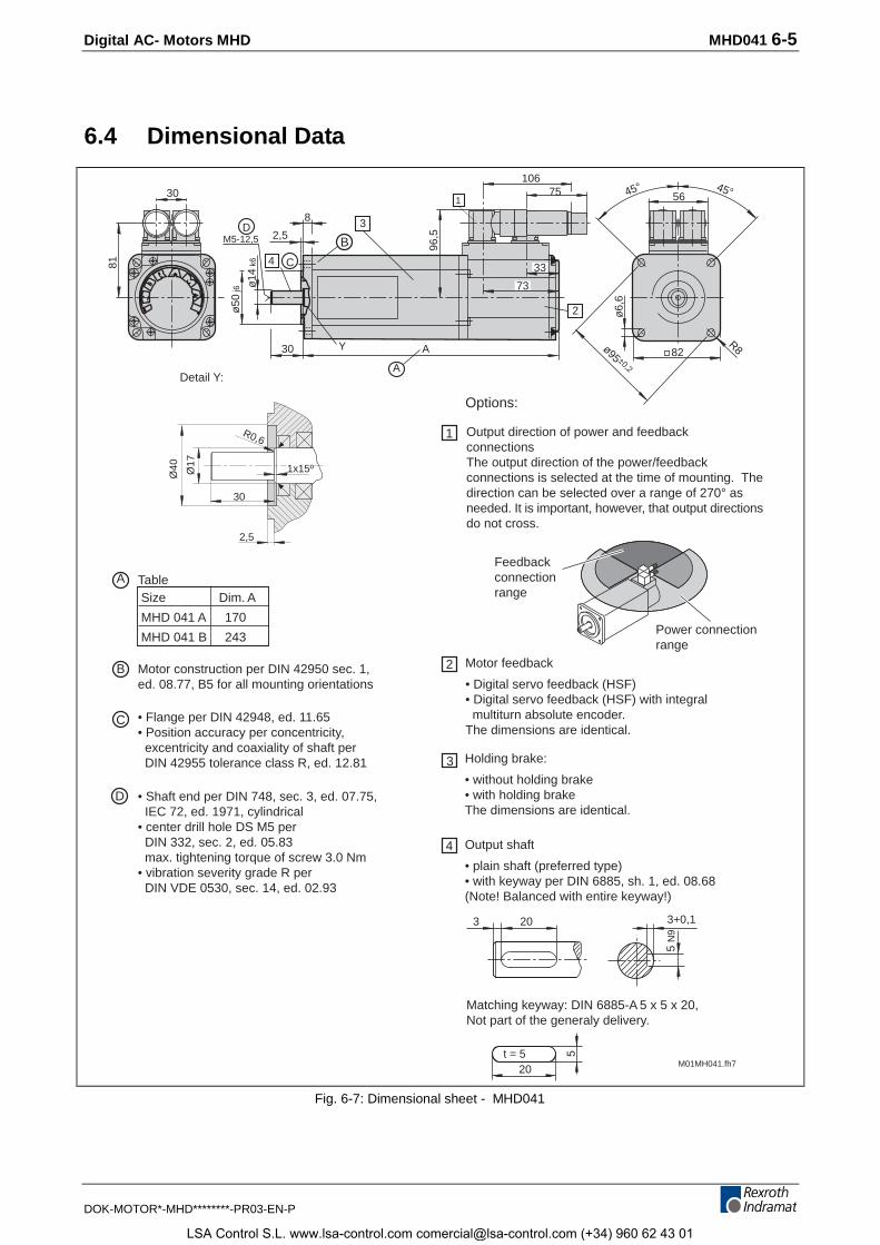
Digital AC- Motors MHD MHD041 6-5
DOK-MOTOR*-MHD********-PR03-EN-P
6.4 Dimensional Data
Size Dim. A
MHD 041 A 170
MHD 041 B 243
M01MH041.fh7
20 3+0,1
5 N
9
Options:
Holding brake:
• without holding brake• with holding brakeThe dimensions are identical.
Output shaft
• plain shaft (preferred type)• with keyway per DIN 6885, sh. 1, ed. 08.68(Note! Balanced with entire keyway!)
Matching keyway: DIN 6885-A 5 x 5 x 20,Not part of the generaly delivery.
3
Motor feedback
• Digital servo feedback (HSF)• Digital servo feedback (HSF) with integral multiturn absolute encoder.The dimensions are identical.
2
1
3
4
20
5t = 5
Motor construction per DIN 42950 sec. 1,ed. 08.77, B5 for all mounting orientations
• Flange per DIN 42948, ed. 11.65• Position accuracy per concentricity, excentricity and coaxiality of shaft per DIN 42955 tolerance class R, ed. 12.81
• Shaft end per DIN 748, sec. 3, ed. 07.75, IEC 72, ed. 1971, cylindrical• center drill hole DS M5 per DIN 332, sec. 2, ed. 05.83 max. tightening torque of screw 3.0 Nm• vibration severity grade R per DIN VDE 0530, sec. 14, ed. 02.93
45° 45°
82R8
ø6,
6
ø95 ±0,2
2
A30
8
2,5ø
50 j6
ø14
k6
DM5-12,5
4 C
3
Y
Output direction of power and feedbackconnectionsThe output direction of the power/feedbackconnections is selected at the time of mounting. Thedirection can be selected over a range of 270° asneeded. It is important, however, that output directionsdo not cross.
96,5
81
30 56175
106
33
73
Power connectionrange
Feedbackconnectionrange
Table
B
C
B
A
D
ADetail Y:
Ø17
Ø40
R0,6
1x15º
30
2,5
Fig. 6-7: Dimensional sheet - MHD041
LSA Control S.L. www.lsa-control.com [email protected] (+34) 960 62 43 01
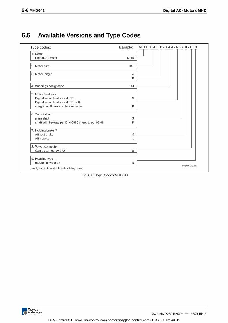
6-6 MHD041 Digital AC- Motors MHD
DOK-MOTOR*-MHD********-PR03-EN-P
6.5 Available Versions and Type Codes
1. NameDigital AC motor MHD
2. Motor size 041
3. Motor length AB
4. Windings designation 144
5. Motor feedbackDigital servo feedback (HSF) NDigital servo feedback (HSF) withintegral multiturn absolute encoder P
6. Output shaftplain shaft Gshaft with keyway per DIN 6885 sheet 1, ed. 08.68 P
7. Holding brake 1)
without brake 0with brake 1
8. Power connectorCan be turned by 270° U
9. Housing typenatural convection N
Type codes: Eample: M H D 0 4 1 B - 1 4 4 - N G 0 - U N
T01MH041.fh71) only length B available with holding brake
Fig. 6-8: Type Codes MHD041
LSA Control S.L. www.lsa-control.com [email protected] (+34) 960 62 43 01
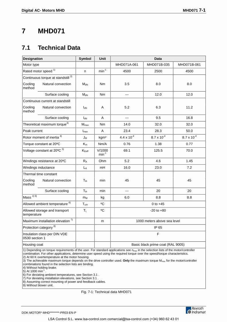
Digital AC- Motors MHD MHD071 7-1
DOK-MOTOR*-MHD********-PR03-EN-P
7 MHD071
7.1 Technical Data
Designation Symbol Unit Data
Motor type MHD071A-061 MHD071B-035 MHD071B-061
Rated motor speed 1) n min-1 4500 2500 4500
Continuous torque at standstill 2)
Coolingmethod
Natural convection MdN Nm 3.5 8.0 8.0
Surface cooling MdN Nm --- 12.0 12.0
Continuous current at standstill
Coolingmethod
Natural convection IdN A 5.2 6.3 11.2
Surface cooling IdN A --- 9.5 16.8
Theoretical maximum torque3) Mmax Nm 14.0 32.0 32.0
Peak current Imax A 23.4 28.3 50.0
Rotor moment of inertia 4) JM kgm² 4.4 x 10⁻⁴ 8.7 x 10⁻⁴ 8.7 x 10⁻⁴
Torque constant at 20ºC Km Nm/A 0.76 1.38 0.77
Voltage constant at 20ºC 5) KEeff V/1000min-1
69.1 125.5 70.0
Windings resistance at 20ºC RA Ohm 5.2 4.6 1.45
Windings inductance LA mH 16.0 23.0 7.2
Thermal time constant
Coolingmethod
Natural convection Tth min 45 45 45
Surface cooling Tth min --- 20 20
Mass 4) 9) mM kg 6.0 8.8 8.8
Allowed ambient temperature 6) Tum ºC 0 to +45
Allowed storage and transporttemperature
TL ºC -20 to +80
Maximum installation elevation 7) m 1000 meters above sea level
Protection category 8) IP 65
Insulation class per DIN VDE0530 section 1
F
Housing coat Basic black prime coat (RAL 9005)
1) Depending on torque requirements of the user. For standard applications see nmax in the selection lists of the motor/controllercombination. For other applications, determine user speed using the required torque over the speed/torque characteristics.2) At 60 K overtemperature at the motor housing.3) The achievable maximum torque depends on the drive controller used. Only the maximum torque Mmax for the motor/controllercombinations found in the selection lists are binding.4) Without holding brake.5) At 1000 min-1 .6) For deviating ambient temperatures, see Section 3.1 .7) For deviating installation elevations, see Section 3.1 .8) Assuming correct mounting of power and feedback cables.9) Without blower unit.
Fig. 7-1: Technical data MHD071
LSA Control S.L. www.lsa-control.com [email protected] (+34) 960 62 43 01
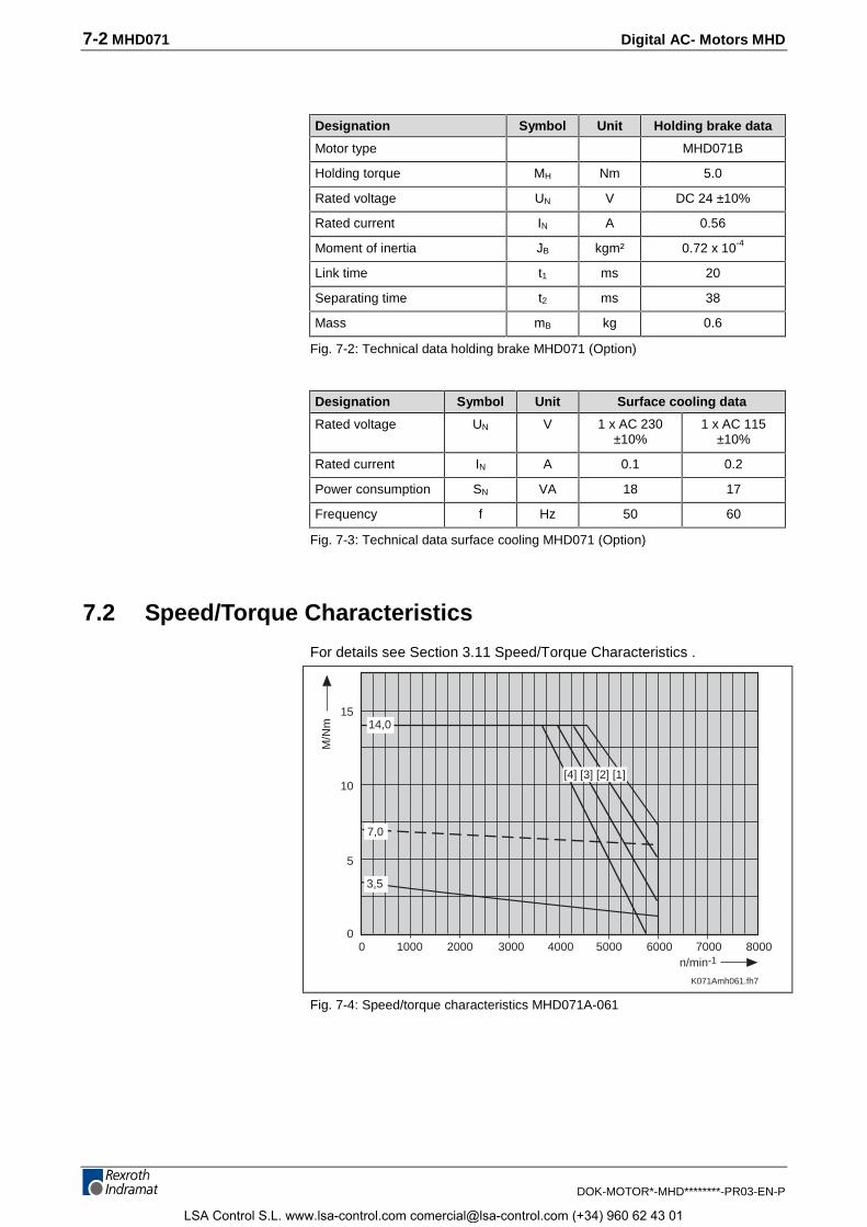
7-2 MHD071 Digital AC- Motors MHD
DOK-MOTOR*-MHD********-PR03-EN-P
Designation Symbol Unit Holding brake data
Motor type MHD071B
Holding torque MH Nm 5.0
Rated voltage UN V DC 24 ±10%
Rated current IN A 0.56
Moment of inertia JB kgm² 0.72 x 10⁻⁴
Link time t1 ms 20
Separating time t2 ms 38
Mass mB kg 0.6
Fig. 7-2: Technical data holding brake MHD071 (Option)
Designation Symbol Unit Surface cooling data
Rated voltage UN V 1 x AC 230±10%
1 x AC 115±10%
Rated current IN A 0.1 0.2
Power consumption SN VA 18 17
Frequency f Hz 50 60
Fig. 7-3: Technical data surface cooling MHD071 (Option)
7.2 Speed/Torque Characteristics
For details see Section 3.11 Speed/Torque Characteristics .
K071Amh061.fh7
n/min-1
M/N
m
10000
2000 3000 4000 5000 60000
5
10
15
7000 8000
14,0
3,5
7,0
[4] [3] [2] [1]
Fig. 7-4: Speed/torque characteristics MHD071A-061
LSA Control S.L. www.lsa-control.com [email protected] (+34) 960 62 43 01
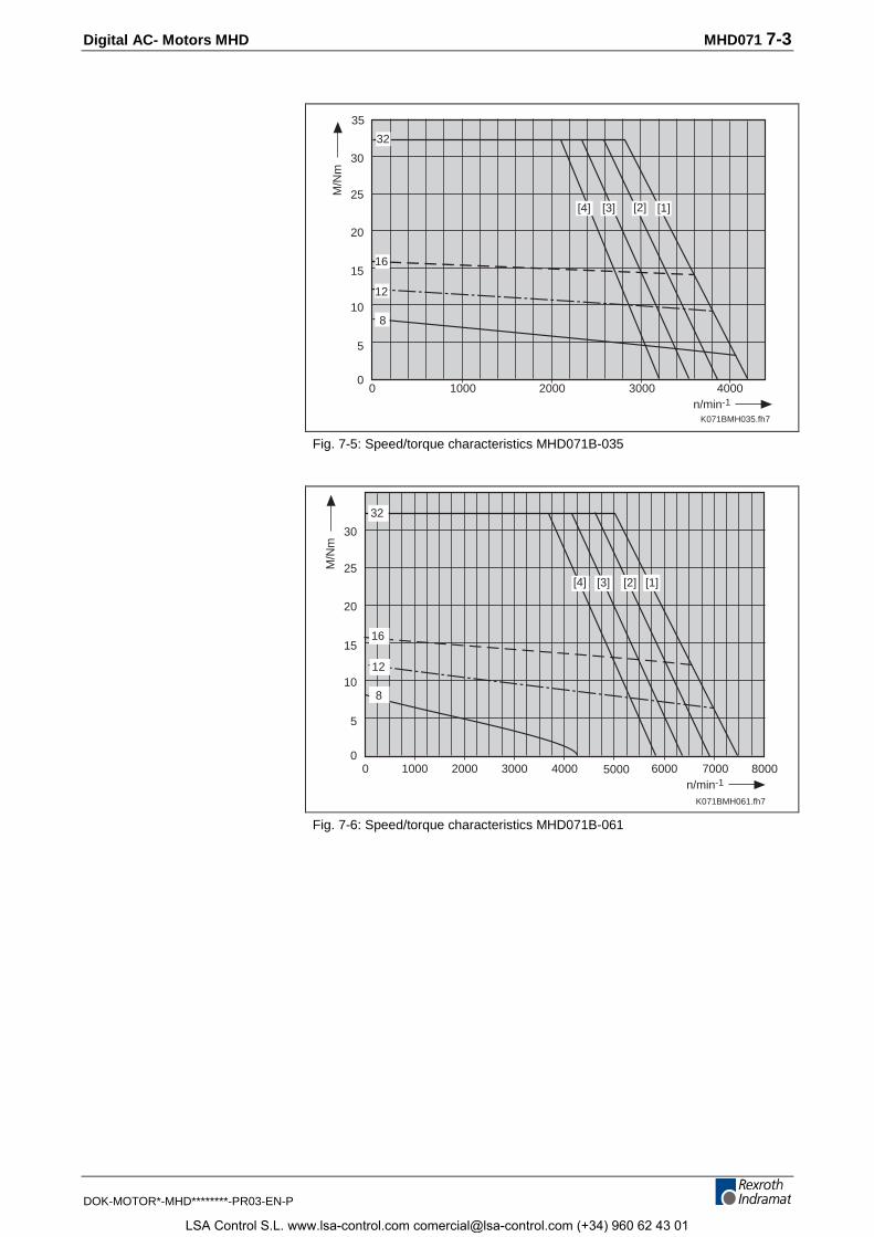
Digital AC- Motors MHD MHD071 7-3
DOK-MOTOR*-MHD********-PR03-EN-P
Datum der Messung 99-05-15
K071BMH035.fh7
10000
2000 3000 40000
5
10
15
20
25
30
n/min-1
M/N
m8
[1][3][4] [2]
32
16
12
35
Fig. 7-5: Speed/torque characteristics MHD071B-035
Datum der Messung 99-05-27
K071BMH061.fh7
10000
2000 3000 4000 6000 70000
5
10
15
20
25
30
32
8
[3] [1]
n/min-1
M/N
m
5000 8000
[2]
12
[4]
16
Fig. 7-6: Speed/torque characteristics MHD071B-061
LSA Control S.L. www.lsa-control.com [email protected] (+34) 960 62 43 01
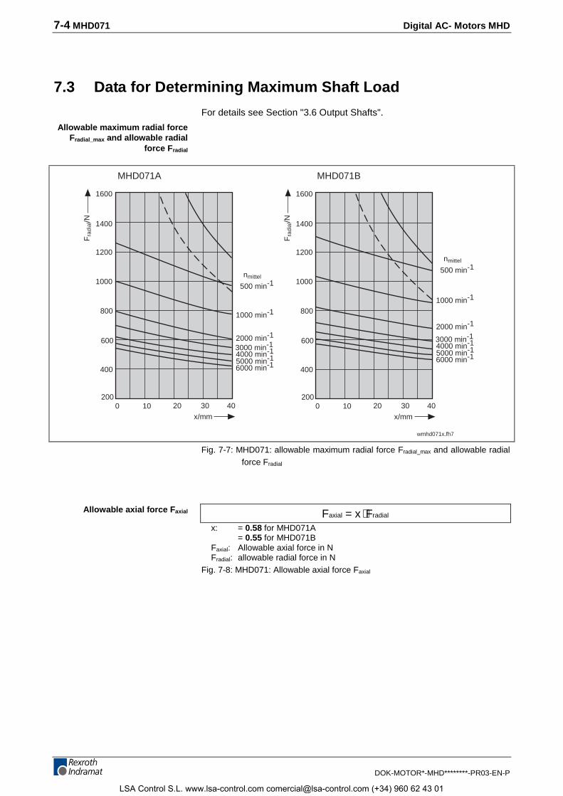
7-4 MHD071 Digital AC- Motors MHD
DOK-MOTOR*-MHD********-PR03-EN-P
7.3 Data for Determining Maximum Shaft Load
For details see Section "3.6 Output Shafts".
nmittel
500 min-1
1000 min-1
2000 min-1
3000 min-14000 min-1
6000 min-15000 min-1
10 20 30x/mm
400
800
1600
Fra
dial
/N
600
1400
40
1200
1000
2000
MHD071BMHD071A
wmhd071x.fh7
10 20 30x/mm
400
800
1600
Fra
dial
/N
600
1400
40
1200
1000
2000
nmittel
500 min-1
1000 min-1
2000 min-1
3000 min-14000 min-1
6000 min-15000 min-1
Fig. 7-7: MHD071: allowable maximum radial force Fradial_max and allowable radialforce Fradial
F x Faxial radial= ⋅x: = 0.58 for MHD071A
= 0.55 for MHD071BFaxial: Allowable axial force in NFradial: allowable radial force in N
Fig. 7-8: MHD071: Allowable axial force Faxial
Allowable maximum radial forceFradial_max and allowable radial
force Fradial
Allowable axial force Faxial
LSA Control S.L. www.lsa-control.com [email protected] (+34) 960 62 43 01
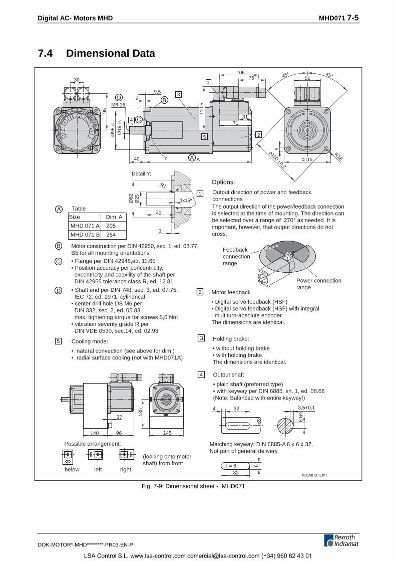
Digital AC- Motors MHD MHD071 7-5
DOK-MOTOR*-MHD********-PR03-EN-P
7.4 Dimensional Data
Size Dim. A
MHD 071 A 205
MHD 071 B 264
below left right
Possible arrangement:
(looking onto motorshaft) from front
Cooling mode:
• natural convection (see above for dim.)• radial surface cooling (not with MHD071A)
5
M01MH071.fh7
32 3,5+0,1
6 N
9
Options:
Holding brake:
• without holding brake• with holding brakeThe dimensions are identical.
4
2
1
3
4
32
6t = 6
Matching keyway: DIN 6885-A 6 x 6 x 32,Not part of general delivery.
Motor feedback
• Digital servo feedback (HSF)• Digital servo feedback (HSF) with integral multiturn-absolute encoderThe dimensions are identical.
Output shaft
• plain shaft (preferred type)• with keyway per DIN 6885, sh. 1, ed. 08.68(Note: Balanced with entire keyway!)
9,5
Ø95
j6
4Ø
19 k
6
3M6-16
40 A
3
2
9
115
ø130 ±0,2
R18Y
301
75106
3171
45° 45°56
95
The output direction of the power/feedback connectionis selected at the time of mounting. The direction canbe selected over a range of 270° as needed. It isimportant, however, that output directions do notcross.
Power connectionrange
Feedbackconnectionrange
Detail Y:
Motor construction per DIN 42950, sec. 1, ed. 08.77,B5 for all mounting orientations• Flange per DIN 42948,ed. 11.65• Position accuracy per concentricity, excentricity and coaxility of the shaft per DIN 42955 tolerance class R, ed. 12.81
• Shaft end per DIN 748, sec. 3, ed. 07.75, IEC 72, ed. 1971, cylindrical• center drill hole DS M6 per DIN 332, sec. 2, ed. 05.83 max. tightening torque for screws 5,0 Nm• vibration severity grade R per DIN VDE 0530, sec.14, ed. 02.93
TableA
B
C
D
A
B
C
D
Ø82
Ø25
R1
1x15º
40
3
110,
5
145
135
140
37
96
5
Output direction of power and feedbackconnections
Fig. 7-9: Dimensional sheet - MHD071
LSA Control S.L. www.lsa-control.com [email protected] (+34) 960 62 43 01
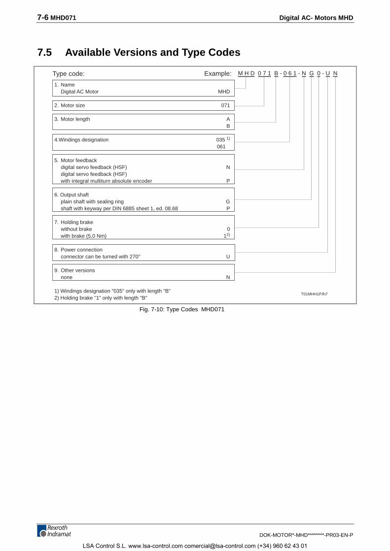
7-6 MHD071 Digital AC- Motors MHD
DOK-MOTOR*-MHD********-PR03-EN-P
7.5 Available Versions and Type Codes
1. NameDigital AC Motor MHD
2. Motor size 071
3. Motor length AB
4.Windings designation 035 1)
061
5. Motor feedbackdigital servo feedback (HSF) Ndigital servo feedback (HSF)with integral multiturn absolute encoder P
6. Output shaftplain shaft with sealing ring Gshaft with keyway per DIN 6885 sheet 1, ed. 08.68 P
7. Holding brakewithout brake 0with brake (5,0 Nm) 12)
8. Power connectionconnector can be turned with 270° U
9. Other versionsnone N
1) Windings designation "035" only with length "B"2) Holding brake "1" only with length "B"
Type code: Example: M H D 0 7 1 B - 0 6 1 - N G 0 - U N
T01MHH1P.fh7
Fig. 7-10: Type Codes MHD071
LSA Control S.L. www.lsa-control.com [email protected] (+34) 960 62 43 01
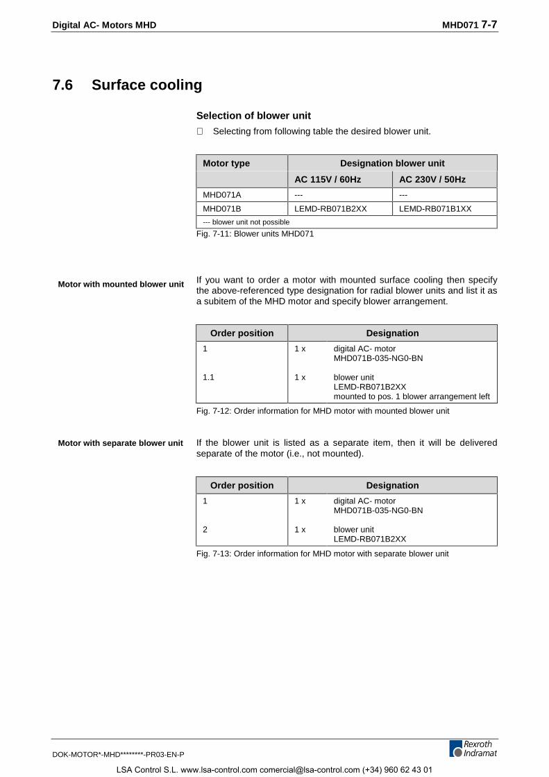
Digital AC- Motors MHD MHD071 7-7
DOK-MOTOR*-MHD********-PR03-EN-P
7.6 Surface cooling
Selection of blower unit
⇒ Selecting from following table the desired blower unit.
Motor type Designation blower unit
AC 115V / 60Hz AC 230V / 50Hz
MHD071A --- ---
MHD071B LEMD-RB071B2XX LEMD-RB071B1XX
--- blower unit not possible
Fig. 7-11: Blower units MHD071
If you want to order a motor with mounted surface cooling then specifythe above-referenced type designation for radial blower units and list it asa subitem of the MHD motor and specify blower arrangement.
Order position Designation
1
1.1
1 x
1 x
digital AC- motorMHD071B-035-NG0-BN
blower unitLEMD-RB071B2XXmounted to pos. 1 blower arrangement left
Fig. 7-12: Order information for MHD motor with mounted blower unit
If the blower unit is listed as a separate item, then it will be deliveredseparate of the motor (i.e., not mounted).
Order position Designation
1
2
1 x
1 x
digital AC- motorMHD071B-035-NG0-BN
blower unitLEMD-RB071B2XX
Fig. 7-13: Order information for MHD motor with separate blower unit
Motor with mounted blower unit
Motor with separate blower unit
LSA Control S.L. www.lsa-control.com [email protected] (+34) 960 62 43 01
7-8 MHD071 Digital AC- Motors MHD
DOK-MOTOR*-MHD********-PR03-EN-P
LSA Control S.L. www.lsa-control.com [email protected] (+34) 960 62 43 01
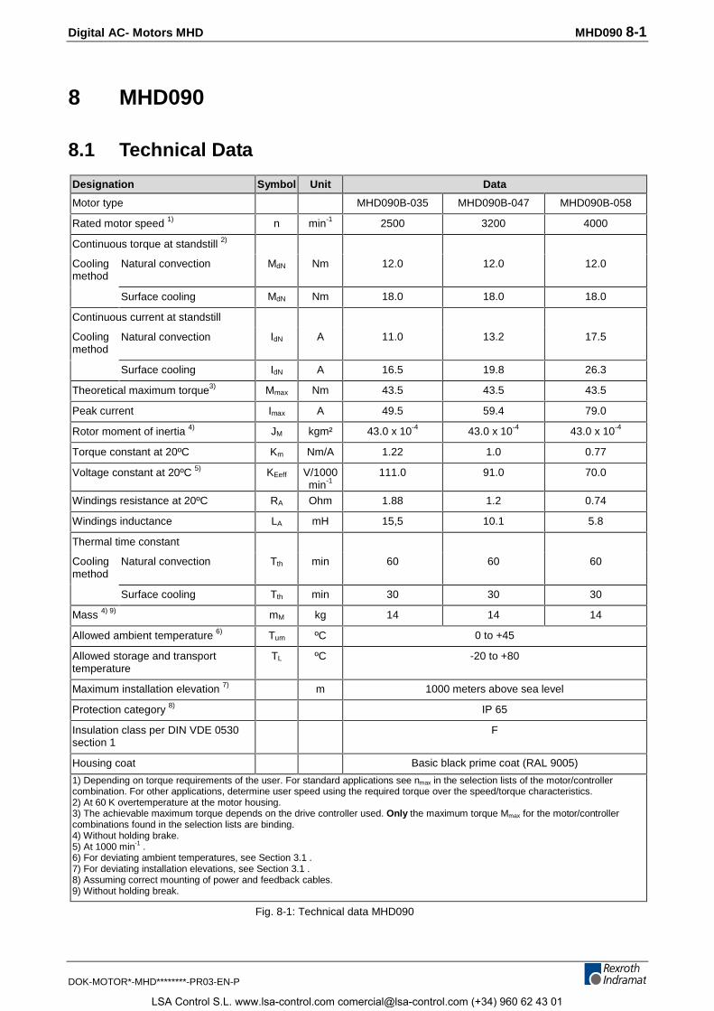
Digital AC- Motors MHD MHD090 8-1
DOK-MOTOR*-MHD********-PR03-EN-P
8 MHD090
8.1 Technical Data
Designation Symbol Unit Data
Motor type MHD090B-035 MHD090B-047 MHD090B-058
Rated motor speed 1) n min-1 2500 3200 4000
Continuous torque at standstill 2)
Coolingmethod
Natural convection MdN Nm 12.0 12.0 12.0
Surface cooling MdN Nm 18.0 18.0 18.0
Continuous current at standstill
Coolingmethod
Natural convection IdN A 11.0 13.2 17.5
Surface cooling IdN A 16.5 19.8 26.3
Theoretical maximum torque3) Mmax Nm 43.5 43.5 43.5
Peak current Imax A 49.5 59.4 79.0
Rotor moment of inertia 4) JM kgm² 43.0 x 10⁻⁴ 43.0 x 10⁻⁴ 43.0 x 10⁻⁴
Torque constant at 20ºC Km Nm/A 1.22 1.0 0.77
Voltage constant at 20ºC 5) KEeff V/1000min-1
111.0 91.0 70.0
Windings resistance at 20ºC RA Ohm 1.88 1.2 0.74
Windings inductance LA mH 15,5 10.1 5.8
Thermal time constant
Coolingmethod
Natural convection Tth min 60 60 60
Surface cooling Tth min 30 30 30
Mass 4) 9) mM kg 14 14 14
Allowed ambient temperature 6) Tum ºC 0 to +45
Allowed storage and transporttemperature
TL ºC -20 to +80
Maximum installation elevation 7) m 1000 meters above sea level
Protection category 8) IP 65
Insulation class per DIN VDE 0530section 1
F
Housing coat Basic black prime coat (RAL 9005)
1) Depending on torque requirements of the user. For standard applications see nmax in the selection lists of the motor/controllercombination. For other applications, determine user speed using the required torque over the speed/torque characteristics.2) At 60 K overtemperature at the motor housing.3) The achievable maximum torque depends on the drive controller used. Only the maximum torque Mmax for the motor/controllercombinations found in the selection lists are binding.4) Without holding brake.5) At 1000 min-1 .6) For deviating ambient temperatures, see Section 3.1 .7) For deviating installation elevations, see Section 3.1 .8) Assuming correct mounting of power and feedback cables.9) Without holding break.
Fig. 8-1: Technical data MHD090
LSA Control S.L. www.lsa-control.com [email protected] (+34) 960 62 43 01
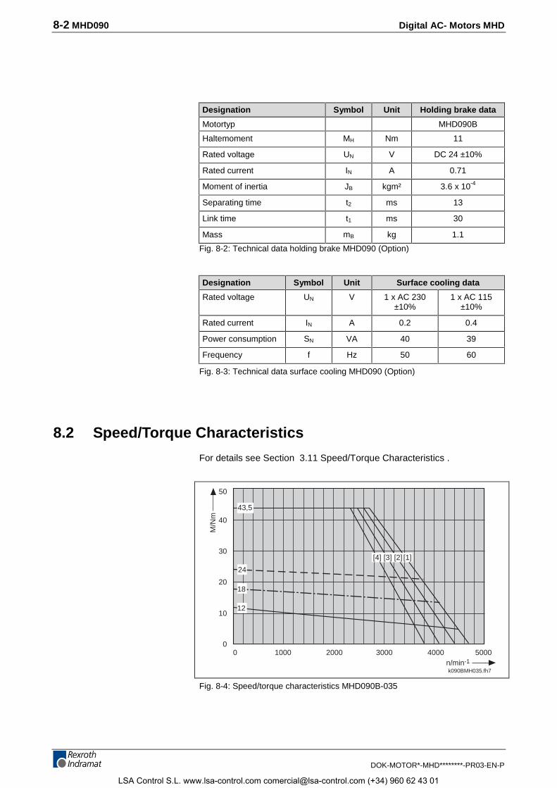
8-2 MHD090 Digital AC- Motors MHD
DOK-MOTOR*-MHD********-PR03-EN-P
Designation Symbol Unit Holding brake data
Motortyp MHD090B
Haltemoment MH Nm 11
Rated voltage UN V DC 24 ±10%
Rated current IN A 0.71
Moment of inertia JB kgm² 3.6 x 10⁻⁴
Separating time t2 ms 13
Link time t1 ms 30
Mass mB kg 1.1
Fig. 8-2: Technical data holding brake MHD090 (Option)
Designation Symbol Unit Surface cooling data
Rated voltage UN V 1 x AC 230±10%
1 x AC 115±10%
Rated current IN A 0.2 0.4
Power consumption SN VA 40 39
Frequency f Hz 50 60
Fig. 8-3: Technical data surface cooling MHD090 (Option)
8.2 Speed/Torque Characteristics
For details see Section 3.11 Speed/Torque Characteristics .
k090BMH035.fh7
10000
2000 3000 40000
10
20
40
30
n/min-1
M/N
m
50
5000
43,5
24
12
[4] [3] [2] [1]
18
Fig. 8-4: Speed/torque characteristics MHD090B-035
LSA Control S.L. www.lsa-control.com [email protected] (+34) 960 62 43 01
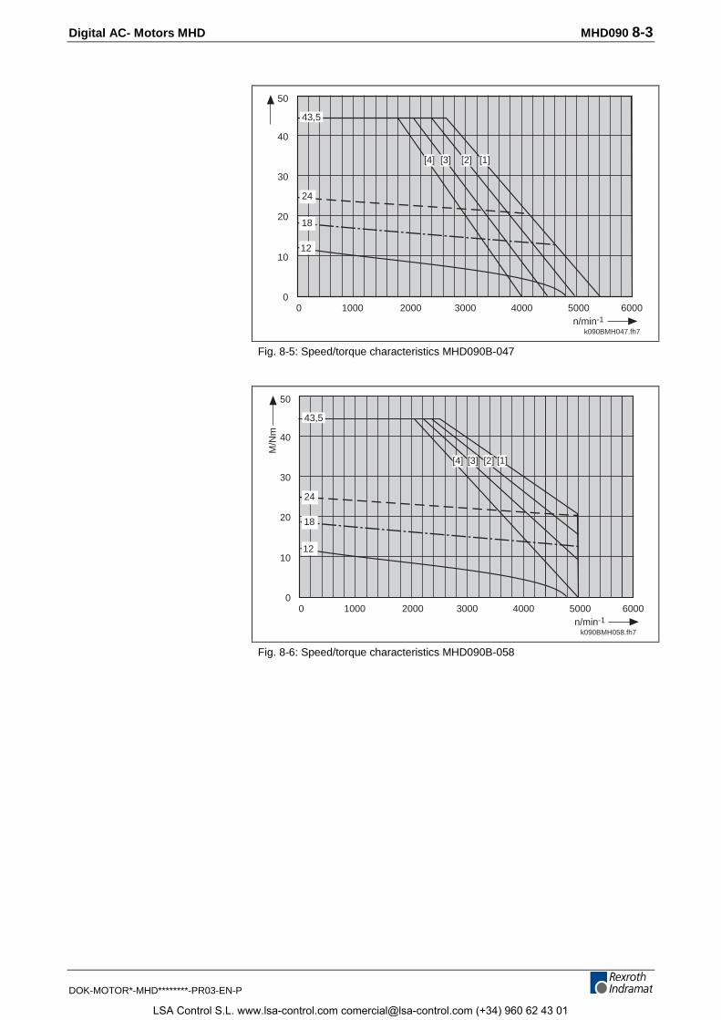
Digital AC- Motors MHD MHD090 8-3
DOK-MOTOR*-MHD********-PR03-EN-P
Datum der Messung 97-04-08= Messung für MHD090B-058zum Erstellzeitpunkt lag keine andereMessung vor!
k090BMH047.fh7
10000
2000 3000 40000
10
20
40
30
n/min-1
50
43,5
12
24
[2][3][4] [1]
5000 6000
18
Fig. 8-5: Speed/torque characteristics MHD090B-047
Datum der Messung 97-04-08
k090BMH058.fh7
10000
2000 3000 40000
10
20
40
30
n/min-1
M/N
m
50
43,5
12
24
[2][3][4] [1]
5000 6000
18
Fig. 8-6: Speed/torque characteristics MHD090B-058
LSA Control S.L. www.lsa-control.com [email protected] (+34) 960 62 43 01
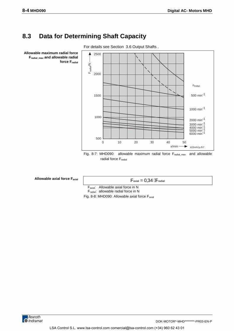
8-4 MHD090 Digital AC- Motors MHD
DOK-MOTOR*-MHD********-PR03-EN-P
8.3 Data for Determining Shaft Capacity
For details see Section 3.6 Output Shafts .
0 10 20x/mm
nmittel
500 min-1
1000 min-1
2000 min-1
3000 min-14000 min-1
6000 min-1
Fra
dial
/N
5000 min-1
1000
k03mhi1p.fh7
30
1500
2000
2500
40 50500
Fig. 8-7: MHD090: allowable maximum radial force Fradial_max and allowableradial force Fradial
F Faxial radial= ⋅0 34,Faxial: Allowable axial force in NFradial: allowable radial force in N
Fig. 8-8: MHD090: Allowable axial force Faxial
Allowable maximum radial forceFradial_max and allowable radial
force Fradial
Allowable axial force Faxial
LSA Control S.L. www.lsa-control.com [email protected] (+34) 960 62 43 01
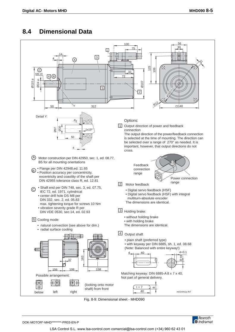
Digital AC- Motors MHD MHD090 8-5
DOK-MOTOR*-MHD********-PR03-EN-P
8.4 Dimensional Data
m01mhi1p.fh7
40 4+0,1
8 N
9
4
3
4
40
8t = 7
125
109
11
R12140312
Ø11
0 j6
Ø24
k6
BM8-19
4
C
A
144
50
ø165
±0,2
Y
Ø10
7
5
72
32
2
158
163
156
37
108
below left right
Possible arrangement:
(looking onto motorshaft) from front
Cooling mode:
• natural convection (see above for dim.)• radial surface cooling
175
1003056
B
C
A
2
1
Ø30
Ø97
R1
1x15º
50
4
3
5
Options:
Holding brake:
• without holding brake• with holding brakeThe dimensions are identical.
Matching keyway: DIN 6885-A 8 x 7 x 40,Not part of general delivery.
Motor feedback
• Digital servo feedback (HSF)• Digital servo feedback (HSF) with integral multiturn-absolute encoderThe dimensions are identical.
Output shaft
• plain shaft (preferred type)• with keyway per DIN 6885, sh. 1, ed. 08.68(Note: Balanced with entire keyway!)
Output direction of power and feedbackconnectionThe output direction of the power/feedback connectionis selected at the time of mounting. The direction canbe selected over a range of 270° as needed. It isimportant, however, that output directions do notcross.
Power connectionrange
Feedbackconnectionrange
Detail Y:
Motor construction per DIN 42950, sec. 1, ed. 08.77,B5 for all mounting orientations
• Flange per DIN 42948,ed. 11.65• Position accuracy per concentricity, excentricity and coaxility of the shaft per DIN 42955 tolerance class R, ed. 12.81
• Shaft end per DIN 748, sec. 3, ed. 07.75, IEC 72, ed. 1971, cylindrical• center drill hole DS M8 per DIN 332, sec. 2, ed. 05.83 max. tightening torque for screws 10 Nm• vibration severity grade R per DIN VDE 0530, sec.14, ed. 02.93
Fig. 8-9: Dimensional sheet - MHD090
LSA Control S.L. www.lsa-control.com [email protected] (+34) 960 62 43 01
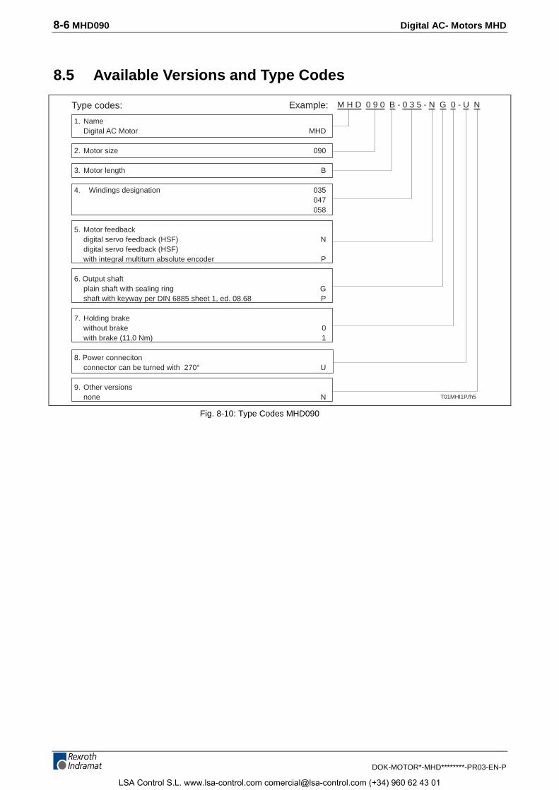
8-6 MHD090 Digital AC- Motors MHD
DOK-MOTOR*-MHD********-PR03-EN-P
8.5 Available Versions and Type Codes
1. NameDigital AC Motor MHD
2. Motor size 090
3. Motor length B
4. Windings designation 035047058
5. Motor feedbackdigital servo feedback (HSF) Ndigital servo feedback (HSF)with integral multiturn absolute encoder P
6. Output shaftplain shaft with sealing ring Gshaft with keyway per DIN 6885 sheet 1, ed. 08.68 P
7. Holding brakewithout brake 0with brake (11,0 Nm) 1
8. Power connecitonconnector can be turned with 270° U
9. Other versionsnone N
Type codes: Example: M H D 0 9 0 B - 0 3 5 - N G 0 - U N
T01MHI1P.fh5
Fig. 8-10: Type Codes MHD090
LSA Control S.L. www.lsa-control.com [email protected] (+34) 960 62 43 01
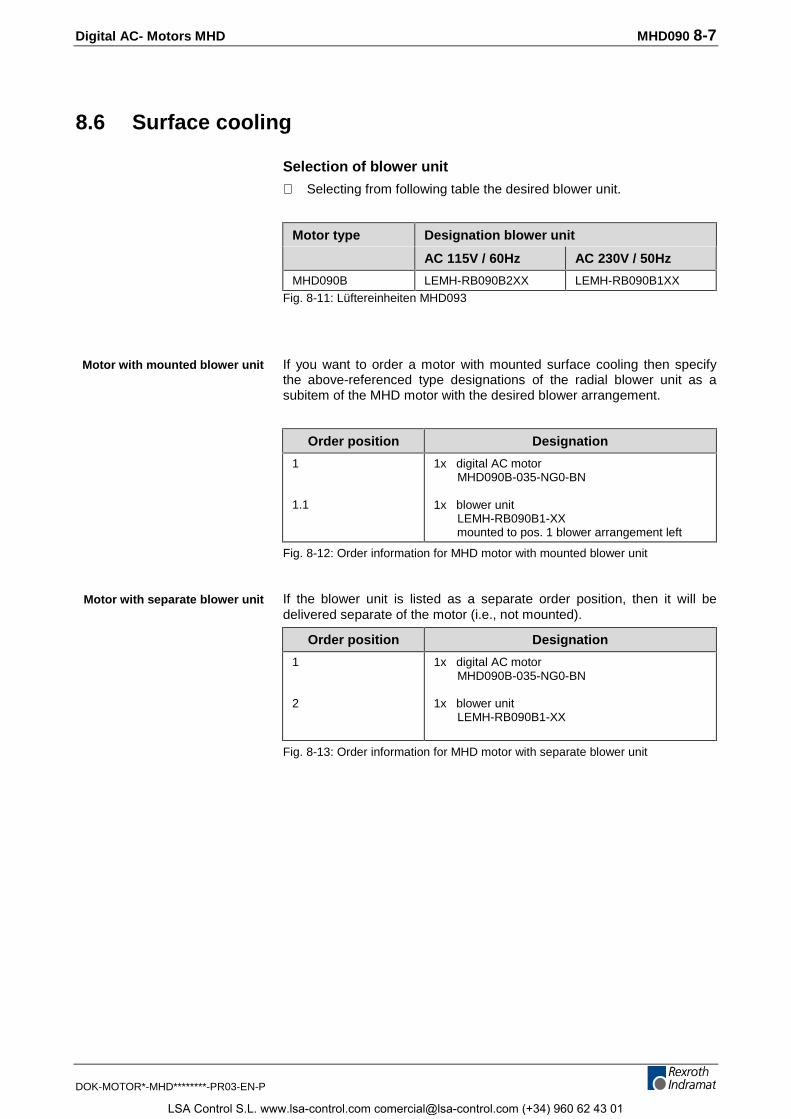
Digital AC- Motors MHD MHD090 8-7
DOK-MOTOR*-MHD********-PR03-EN-P
8.6 Surface cooling
Selection of blower unit
⇒ Selecting from following table the desired blower unit.
Motor type Designation blower unit
AC 115V / 60Hz AC 230V / 50Hz
MHD090B LEMH-RB090B2XX LEMH-RB090B1XX
Fig. 8-11: Lüftereinheiten MHD093
If you want to order a motor with mounted surface cooling then specifythe above-referenced type designations of the radial blower unit as asubitem of the MHD motor with the desired blower arrangement.
Order position Designation
1
1.1
1x digital AC motor MHD090B-035-NG0-BN
1x blower unit LEMH-RB090B1-XX mounted to pos. 1 blower arrangement left
Fig. 8-12: Order information for MHD motor with mounted blower unit
If the blower unit is listed as a separate order position, then it will bedelivered separate of the motor (i.e., not mounted).
Order position Designation
1
2
1x digital AC motor MHD090B-035-NG0-BN
1x blower unit LEMH-RB090B1-XX
Fig. 8-13: Order information for MHD motor with separate blower unit
Motor with mounted blower unit
Motor with separate blower unit
LSA Control S.L. www.lsa-control.com [email protected] (+34) 960 62 43 01

8-8 MHD090 Digital AC- Motors MHD
DOK-MOTOR*-MHD********-PR03-EN-P
LSA Control S.L. www.lsa-control.com [email protected] (+34) 960 62 43 01
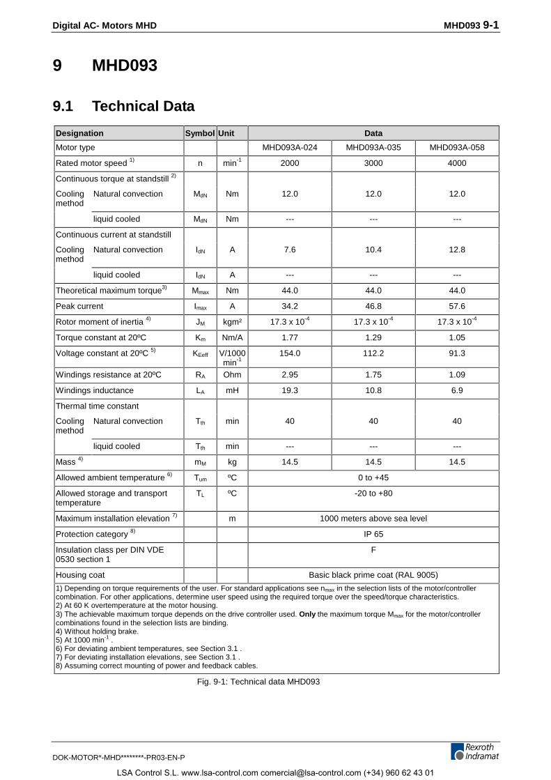
Digital AC- Motors MHD MHD093 9-1
DOK-MOTOR*-MHD********-PR03-EN-P
9 MHD093
9.1 Technical Data
Designation Symbol Unit Data
Motor type MHD093A-024 MHD093A-035 MHD093A-058
Rated motor speed 1) n min-1 2000 3000 4000
Continuous torque at standstill 2)
Coolingmethod
Natural convection MdN Nm 12.0 12.0 12.0
liquid cooled MdN Nm --- --- ---
Continuous current at standstill
Coolingmethod
Natural convection IdN A 7.6 10.4 12.8
liquid cooled IdN A --- --- ---
Theoretical maximum torque3) Mmax Nm 44.0 44.0 44.0
Peak current Imax A 34.2 46.8 57.6
Rotor moment of inertia 4) JM kgm² 17.3 x 10⁻⁴ 17.3 x 10⁻⁴ 17.3 x 10⁻⁴
Torque constant at 20ºC Km Nm/A 1.77 1.29 1.05
Voltage constant at 20ºC 5) KEeff V/1000min-1
154.0 112.2 91.3
Windings resistance at 20ºC RA Ohm 2.95 1.75 1.09
Windings inductance LA mH 19.3 10.8 6.9
Thermal time constant
Coolingmethod
Natural convection Tth min 40 40 40
liquid cooled Tth min --- --- ---
Mass 4) mM kg 14.5 14.5 14.5
Allowed ambient temperature 6) Tum ºC 0 to +45
Allowed storage and transporttemperature
TL ºC -20 to +80
Maximum installation elevation 7) m 1000 meters above sea level
Protection category 8) IP 65
Insulation class per DIN VDE0530 section 1
F
Housing coat Basic black prime coat (RAL 9005)
1) Depending on torque requirements of the user. For standard applications see nmax in the selection lists of the motor/controllercombination. For other applications, determine user speed using the required torque over the speed/torque characteristics.2) At 60 K overtemperature at the motor housing.3) The achievable maximum torque depends on the drive controller used. Only the maximum torque Mmax for the motor/controllercombinations found in the selection lists are binding.4) Without holding brake.5) At 1000 min-1 .6) For deviating ambient temperatures, see Section 3.1 .7) For deviating installation elevations, see Section 3.1 .8) Assuming correct mounting of power and feedback cables.
Fig. 9-1: Technical data MHD093
LSA Control S.L. www.lsa-control.com [email protected] (+34) 960 62 43 01
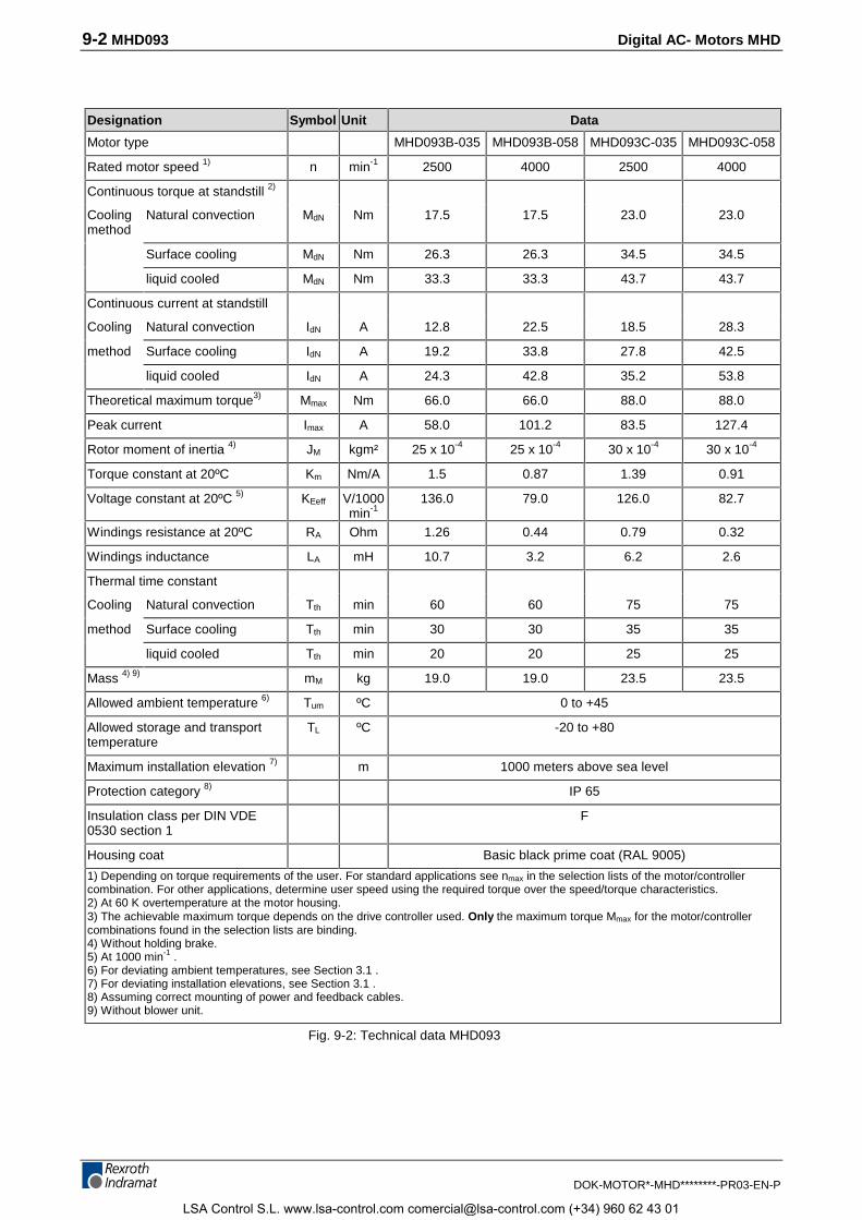
9-2 MHD093 Digital AC- Motors MHD
DOK-MOTOR*-MHD********-PR03-EN-P
Designation Symbol Unit Data
Motor type MHD093B-035 MHD093B-058 MHD093C-035 MHD093C-058
Rated motor speed 1) n min-1 2500 4000 2500 4000
Continuous torque at standstill 2)
Coolingmethod
Natural convection MdN Nm 17.5 17.5 23.0 23.0
Surface cooling MdN Nm 26.3 26.3 34.5 34.5
liquid cooled MdN Nm 33.3 33.3 43.7 43.7
Continuous current at standstill
Cooling Natural convection IdN A 12.8 22.5 18.5 28.3
method Surface cooling IdN A 19.2 33.8 27.8 42.5
liquid cooled IdN A 24.3 42.8 35.2 53.8
Theoretical maximum torque3) Mmax Nm 66.0 66.0 88.0 88.0
Peak current Imax A 58.0 101.2 83.5 127.4
Rotor moment of inertia 4) JM kgm² 25 x 10-4 25 x 10-4 30 x 10-4 30 x 10-4
Torque constant at 20ºC Km Nm/A 1.5 0.87 1.39 0.91
Voltage constant at 20ºC 5) KEeff V/1000min-1
136.0 79.0 126.0 82.7
Windings resistance at 20ºC RA Ohm 1.26 0.44 0.79 0.32
Windings inductance LA mH 10.7 3.2 6.2 2.6
Thermal time constant
Cooling Natural convection Tth min 60 60 75 75
method Surface cooling Tth min 30 30 35 35
liquid cooled Tth min 20 20 25 25
Mass 4) 9) mM kg 19.0 19.0 23.5 23.5
Allowed ambient temperature 6) Tum ºC 0 to +45
Allowed storage and transporttemperature
TL ºC -20 to +80
Maximum installation elevation 7) m 1000 meters above sea level
Protection category 8) IP 65
Insulation class per DIN VDE0530 section 1
F
Housing coat Basic black prime coat (RAL 9005)
1) Depending on torque requirements of the user. For standard applications see nmax in the selection lists of the motor/controllercombination. For other applications, determine user speed using the required torque over the speed/torque characteristics.2) At 60 K overtemperature at the motor housing.3) The achievable maximum torque depends on the drive controller used. Only the maximum torque Mmax for the motor/controllercombinations found in the selection lists are binding.4) Without holding brake.5) At 1000 min-1 .6) For deviating ambient temperatures, see Section 3.1 .7) For deviating installation elevations, see Section 3.1 .8) Assuming correct mounting of power and feedback cables.9) Without blower unit.
Fig. 9-2: Technical data MHD093
LSA Control S.L. www.lsa-control.com [email protected] (+34) 960 62 43 01
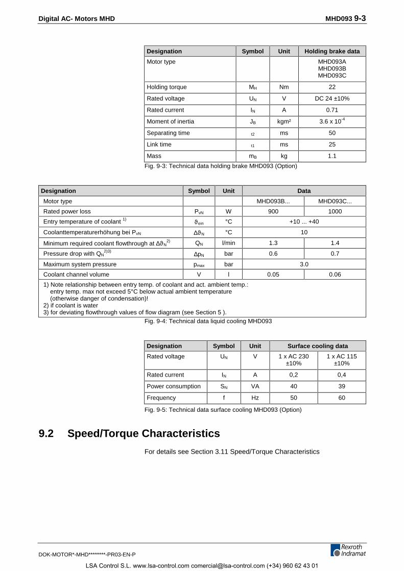
Digital AC- Motors MHD MHD093 9-3
DOK-MOTOR*-MHD********-PR03-EN-P
Designation Symbol Unit Holding brake data
Motor type MHD093AMHD093BMHD093C
Holding torque MH Nm 22
Rated voltage UN V DC 24 ±10%
Rated current IN A 0.71
Moment of inertia JB kgm² 3.6 x 10⁻⁴
Separating time t2 ms 50
Link time t1 ms 25
Mass mB kg 1.1
Fig. 9-3: Technical data holding brake MHD093 (Option)
Designation Symbol Unit Data
Motor type MHD093B... MHD093C...
Rated power loss PvN W 900 1000
Entry temperature of coolant 1) ϑein °C +10 ... +40
Coolanttemperaturerhöhung bei PvN ∆ϑN °C 10
Minimum required coolant flowthrough at ∆ϑN2) QN l/min 1.3 1.4
Pressure drop with QN2)3) ∆pN bar 0.6 0.7
Maximum system pressure pmax bar 3.0
Coolant channel volume V l 0.05 0.06
1) Note relationship between entry temp. of coolant and act. ambient temp.: entry temp. max not exceed 5°C below actual ambient temperature (otherwise danger of condensation)!2) if coolant is water3) for deviating flowthrough values of flow diagram (see Section 5 ).
Fig. 9-4: Technical data liquid cooling MHD093
Designation Symbol Unit Surface cooling data
Rated voltage UN V 1 x AC 230±10%
1 x AC 115±10%
Rated current IN A 0,2 0,4
Power consumption SN VA 40 39
Frequency f Hz 50 60
Fig. 9-5: Technical data surface cooling MHD093 (Option)
9.2 Speed/Torque Characteristics
For details see Section 3.11 Speed/Torque Characteristics
LSA Control S.L. www.lsa-control.com [email protected] (+34) 960 62 43 01
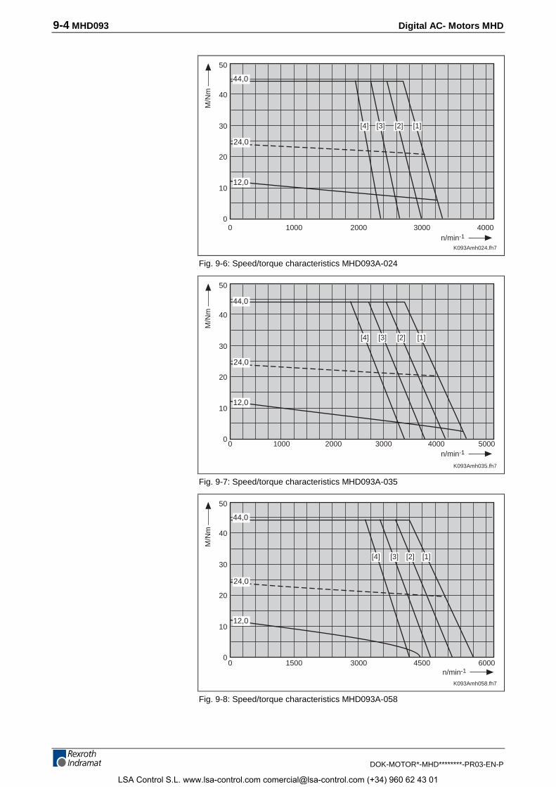
9-4 MHD093 Digital AC- Motors MHD
DOK-MOTOR*-MHD********-PR03-EN-P
K093Amh024.fh7
10000
2000 3000 40000
10
20
40
30
n/min-1
M/N
m
50
[1][2][3][4]
12,0
24,0
44,0
Fig. 9-6: Speed/torque characteristics MHD093A-024
Datum der Messung: 22.07.99
K093Amh035.fh7
10000
2000 3000 40000
10
20
40
30
n/min-1
M/N
m
50
[1][2][3][4]
12,0
24,0
44,0
5000
Fig. 9-7: Speed/torque characteristics MHD093A-035
K093Amh058.fh7
15000
3000 4500 60000
10
20
40
30
n/min-1
M/N
m
50
[1][2][3][4]
12,0
24,0
44,0
Fig. 9-8: Speed/torque characteristics MHD093A-058
LSA Control S.L. www.lsa-control.com [email protected] (+34) 960 62 43 01
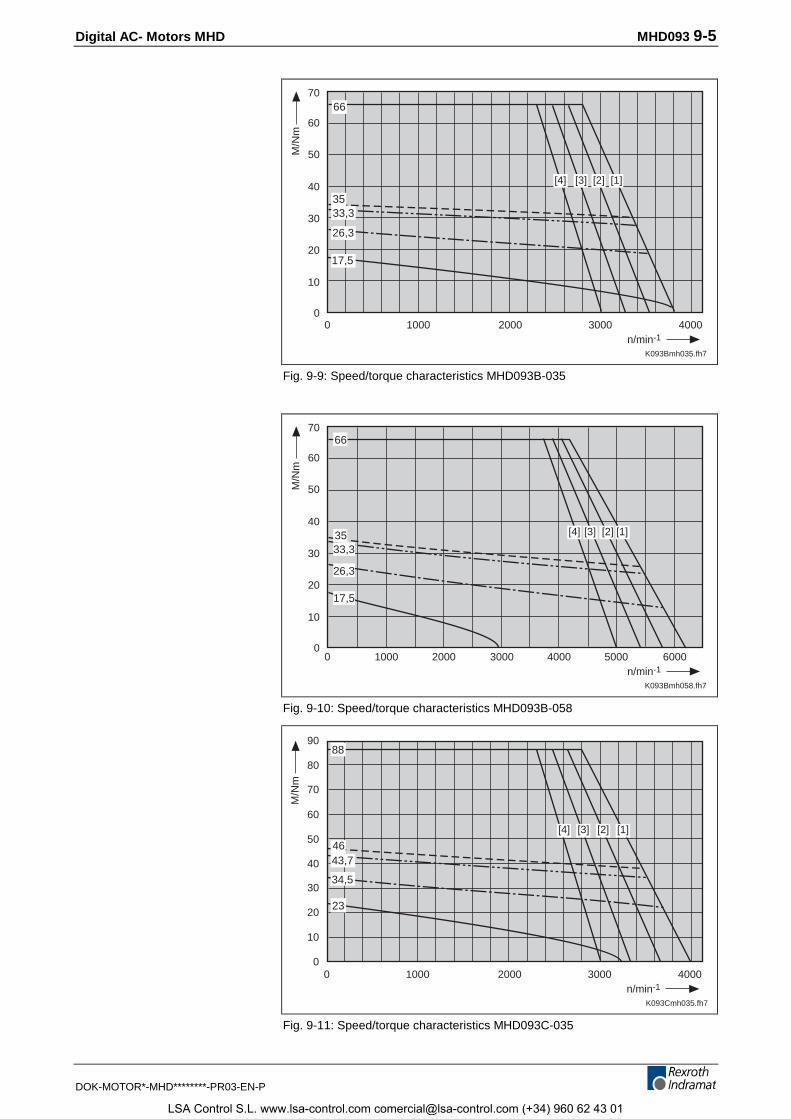
Digital AC- Motors MHD MHD093 9-5
DOK-MOTOR*-MHD********-PR03-EN-P
K093Bmh035.fh7
10000
2000 3000 40000
10
20
40
30
n/min-1
M/N
m
50
60
70
[1][2][3][4]
66
3533,3
26,3
17,5
Fig. 9-9: Speed/torque characteristics MHD093B-035
K093Bmh058.fh7
10000
2000 30000
10
20
40
30
n/min-1
M/N
m
50
[1]
60
70
4000 5000 6000
[2][3][4]
66
26,3
17,5
33,335
Fig. 9-10: Speed/torque characteristics MHD093B-058
K093Cmh035.fh7
10000
2000 3000 40000
10
20
40
30
n/min-1
M/N
m
50
60
70
80
90
[1][2][3][4]
88
46
34,5
43,7
23
Fig. 9-11: Speed/torque characteristics MHD093C-035
LSA Control S.L. www.lsa-control.com [email protected] (+34) 960 62 43 01
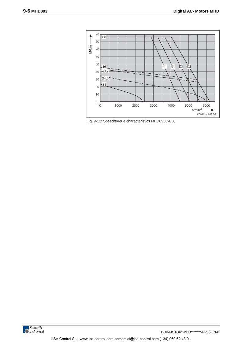
9-6 MHD093 Digital AC- Motors MHD
DOK-MOTOR*-MHD********-PR03-EN-P
K093Cmh058.fh7
1000 2000 30000n/min-1
M/N
m
[1]
4000 5000 6000
[4]
88
23
90
80
70
60
50
40
30
20
10
0
34,5
[3] [2]4643,7
Fig. 9-12: Speed/torque characteristics MHD093C-058
LSA Control S.L. www.lsa-control.com [email protected] (+34) 960 62 43 01
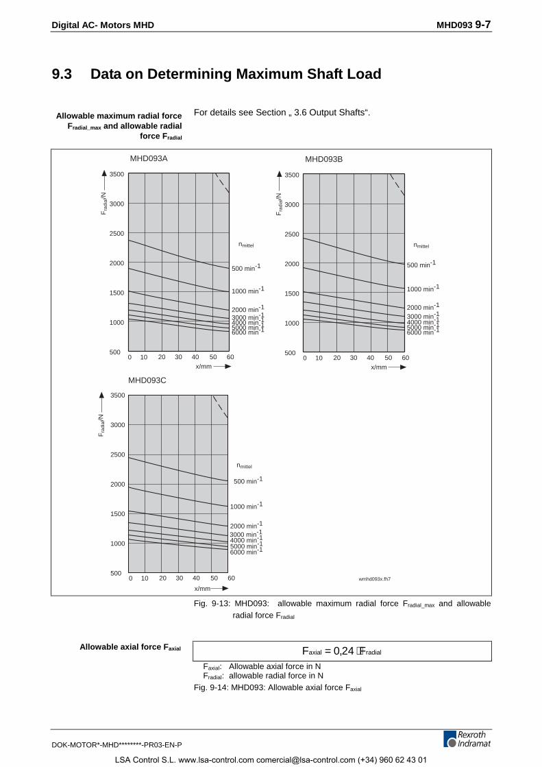
Digital AC- Motors MHD MHD093 9-7
DOK-MOTOR*-MHD********-PR03-EN-P
9.3 Data on Determining Maximum Shaft Load
For details see Section „ 3.6 Output Shafts“.
MHD093C
3500
3000
2500
2000
1500
1000
500
3500
3000
2500
2000
1500
1000
500
3500
3000
2500
2000
1500
1000
500
wmhd093x.fh7
10 20 30x/mm
Fra
dial
/N
400
nmittel
500 min-1
1000 min-1
2000 min-1
3000 min-14000 min-1
6000 min-15000 min-1
x/mm
Fra
dial
/N
50 60
MHD093A
10 20 30 400 50 60
nmittel
500 min-1
1000 min-1
2000 min-1
3000 min-14000 min-1
6000 min-15000 min-1
10 20 30x/mm
Fra
dial
/N
400
nmittel
500 min-1
1000 min-1
2000 min-1
3000 min-14000 min-1
6000 min-15000 min-1
50 60
MHD093B
Fig. 9-13: MHD093: allowable maximum radial force Fradial_max and allowableradial force Fradial
F Faxial radial= ⋅0 24,Faxial: Allowable axial force in NFradial: allowable radial force in N
Fig. 9-14: MHD093: Allowable axial force Faxial
Allowable maximum radial forceFradial_max and allowable radial
force Fradial
Allowable axial force Faxial
LSA Control S.L. www.lsa-control.com [email protected] (+34) 960 62 43 01
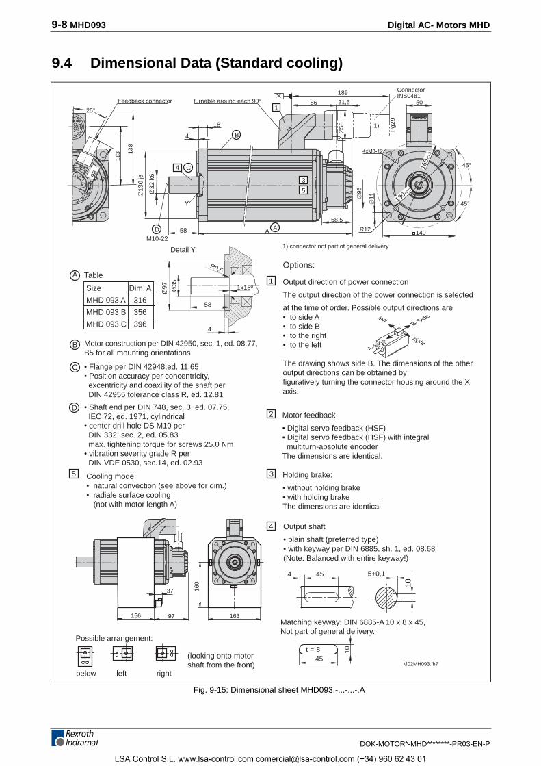
9-8 MHD093 Digital AC- Motors MHD
DOK-MOTOR*-MHD********-PR03-EN-P
9.4 Dimensional Data (Standard cooling)
4xM8-12
1
X
C4
Y
25°
M02MH093.fh7
45 5+0,1
10
Options:
Holding brake:
• without holding brake• with holding brakeThe dimensions are identical.
4
Output direction of power connection
The output direction of the power connection is selected
at the time of order. Possible output directions are• to side A• to side B• to the right• to the left
The drawing shows side B. The dimensions of the otheroutput directions can be obtained byfiguratively turning the connector housing around the Xaxis.
2
1
3
4
45
10t = 8
C
D
B
Motor feedback
• Digital servo feedback (HSF)• Digital servo feedback (HSF) with integral multiturn-absolute encoderThe dimensions are identical.
Matching keyway: DIN 6885-A 10 x 8 x 45,Not part of general delivery.
Output shaft
• plain shaft (preferred type)• with keyway per DIN 6885, sh. 1, ed. 08.68(Note: Balanced with entire keyway!)
Motor construction per DIN 42950, sec. 1, ed. 08.77,B5 for all mounting orientations
• Flange per DIN 42948,ed. 11.65• Position accuracy per concentricity, excentricity and coaxility of the shaft per DIN 42955 tolerance class R, ed. 12.81
• Shaft end per DIN 748, sec. 3, ed. 07.75, IEC 72, ed. 1971, cylindrical• center drill hole DS M10 per DIN 332, sec. 2, ed. 05.83 max. tightening torque for screws 25.0 Nm• vibration severity grade R per DIN VDE 0530, sec.14, ed. 02.93
Table
Size Dim. A
MHD 093 A 316
MHD 093 B 356
MHD 093 C 396
A
below left right
Possible arrangement:
(looking onto motorshaft from the front)
Cooling mode:• natural convection (see above for dim.)• radiale surface cooling
(not with motor length A)
5
Detail Y:
163
160
37
97156
AA
A-Side
B-Sideleft
right
Ø35
Ø97
R0,5
1x15º
58
4
45°
45°
115
Feedback connector 50
140
Æ11
R12
Æ96
58,5
189
31,586
Æ58
3
5
4
18
BÆ
130
j6
M10-2258
Ø32
k6
D
98
113 13
8
ConnectorINS0481
1)
1) connector not part of general delivery
165±
0,3
130±0,2
Pg2
9
turnable around each 90°
Fig. 9-15: Dimensional sheet MHD093.-...-...-.A
LSA Control S.L. www.lsa-control.com [email protected] (+34) 960 62 43 01
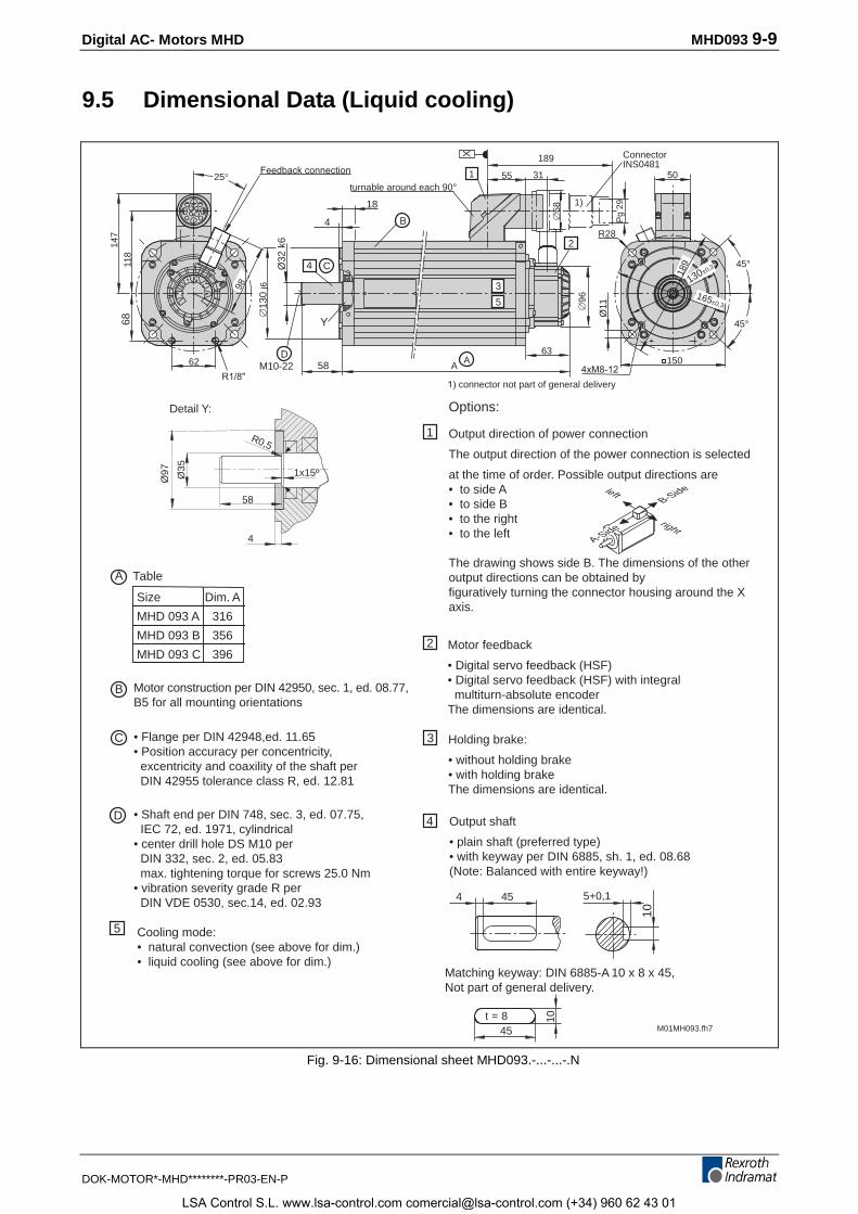
Digital AC- Motors MHD MHD093 9-9
DOK-MOTOR*-MHD********-PR03-EN-P
9.5 Dimensional Data (Liquid cooling)
62
turnable around each 90°
ConnectorINS0481
M01MH093.fh7
45 5+0,1
10
Options:
Holding brake:
• without holding brake• with holding brakeThe dimensions are identical.
4
Output direction of power connection
The output direction of the power connection is selected
at the time of order. Possible output directions are• to side A• to side B• to the right• to the left
The drawing shows side B. The dimensions of the otheroutput directions can be obtained byfiguratively turning the connector housing around the Xaxis.
2
1
3
4
45
10t = 8
C
D
B
Motor feedback
• Digital servo feedback (HSF)• Digital servo feedback (HSF) with integral multiturn-absolute encoderThe dimensions are identical.
Matching keyway: DIN 6885-A 10 x 8 x 45,Not part of general delivery.
Output shaft
• plain shaft (preferred type)• with keyway per DIN 6885, sh. 1, ed. 08.68(Note: Balanced with entire keyway!)
Motor construction per DIN 42950, sec. 1, ed. 08.77,B5 for all mounting orientations
• Flange per DIN 42948,ed. 11.65• Position accuracy per concentricity, excentricity and coaxility of the shaft per DIN 42955 tolerance class R, ed. 12.81
• Shaft end per DIN 748, sec. 3, ed. 07.75, IEC 72, ed. 1971, cylindrical• center drill hole DS M10 per DIN 332, sec. 2, ed. 05.83 max. tightening torque for screws 25.0 Nm• vibration severity grade R per DIN VDE 0530, sec.14, ed. 02.93
Cooling mode:• natural convection (see above for dim.)• liquid cooling (see above for dim.)
5
6814
711
8
25°
98
Æ13
0 j6
M10-22
4
18
58
C4
B
Y
A
63A
X
Pg
29
Æ96
2
45°
45°
Ø11
1504xM8-12
31
189
551
130±0,2
50
Æ58
1)
1) connector not part of general delivery
R28
Detail Y:
Ø35
Ø97
R0,5
1x15º
58
4
Table
Size Dim. A
MHD 093 A 316
MHD 093 B 356
MHD 093 C 396
A
A-Side
B-Sideleft
right
Feedback connection
189
165±0,3
Ø32
k6
D
R1/8"
3
5
Fig. 9-16: Dimensional sheet MHD093.-...-...-.N
LSA Control S.L. www.lsa-control.com [email protected] (+34) 960 62 43 01
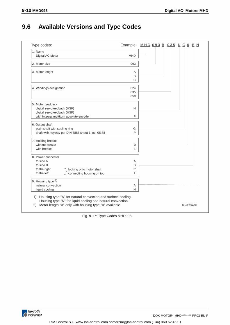
9-10 MHD093 Digital AC- Motors MHD
DOK-MOTOR*-MHD********-PR03-EN-P
9.6 Available Versions and Type Codes
1. NameDigital AC Motor MHD
2. Motor size 093
3. Motor lenght ABC
4. Windings designation 024035058
5. Motor feedbackdigital servofeedback (HSF) Ndigital servofeedback (HSF)with integral multiturn absolute encoder P
6. Output shaftplain shaft with sealing ring Gshaft with keyway per DIN 6885 sheet 1, ed. 08.68 P
7. Holding breakewithout breake 0with breake 1
8. Power connectorto side A Ato side B Bto the right Rto the left L
9. Housing type 1)
natural convection Aliquid cooling N
Type codes: Example: M H D 0 9 3 B - 0 3 5 - N G 0 - B N
T01MH093.fh7
looking onto motor shaftconnecting housing on top
1) Housing type "A" for natural convection and surface cooling.Housing type "N" for liquid cooling and natural convection.
2) Motor length "A" only with housing type "A" available.
Fig. 9-17: Type Codes MHD093
LSA Control S.L. www.lsa-control.com [email protected] (+34) 960 62 43 01
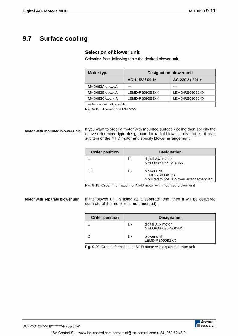
Digital AC- Motors MHD MHD093 9-11
DOK-MOTOR*-MHD********-PR03-EN-P
9.7 Surface cooling
Selection of blower unitSelecting from following table the desired blower unit.
Motor type Designation blower unit
AC 115V / 60Hz AC 230V / 50Hz
MHD093A-...-...-.A --- ---
MHD093B-...-...-.A LEMD-RB090B2XX LEMD-RB090B1XX
MHD093C-...-...-.A LEMD-RB090B2XX LEMD-RB090B1XX
--- blower unit not possible
Fig. 9-18: Blower units MHD093
If you want to order a motor with mounted surface cooling then specify theabove-referenced type designation for radial blower units and list it as asubitem of the MHD motor and specify blower arrangement.
Order position Designation
1
1.1
1 x
1 x
digital AC- motorMHD093B-035-NG0-BN
blower unitLEMD-RB093B2XXmounted to pos. 1 blower arrangement left
Fig. 9-19: Order information for MHD motor with mounted blower unit
If the blower unit is listed as a separate item, then it will be deliveredseparate of the motor (i.e., not mounted).
Order position Designation
1
2
1 x
1 x
digital AC- motorMHD093B-035-NG0-BN
blower unitLEMD-RB090B2XX
Fig. 9-20: Order information for MHD motor with separate blower unit
Motor with mounted blower unit
Motor with separate blower unit
LSA Control S.L. www.lsa-control.com [email protected] (+34) 960 62 43 01
9-12 MHD093 Digital AC- Motors MHD
DOK-MOTOR*-MHD********-PR03-EN-P
LSA Control S.L. www.lsa-control.com [email protected] (+34) 960 62 43 01
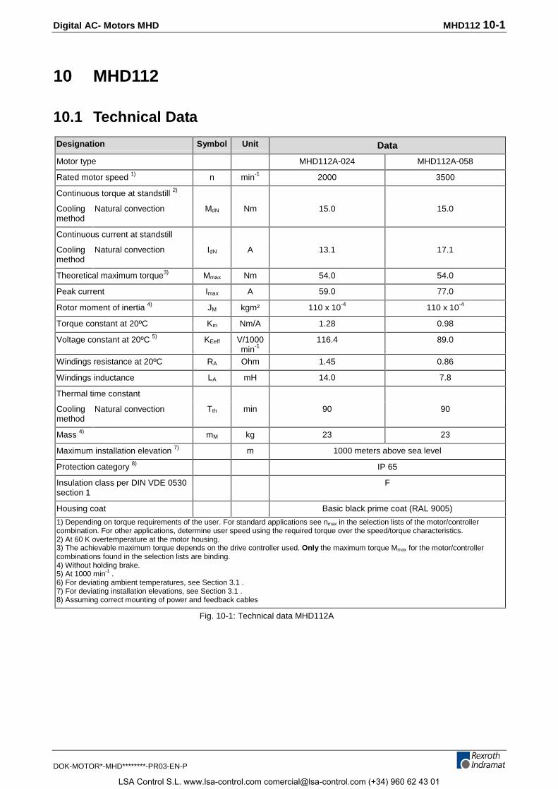
Digital AC- Motors MHD MHD112 10-1
DOK-MOTOR*-MHD********-PR03-EN-P
10 MHD112
10.1 Technical Data
Designation Symbol Unit Data
Motor type MHD112A-024 MHD112A-058
Rated motor speed 1) n min-1 2000 3500
Continuous torque at standstill 2)
Coolingmethod
Natural convection MdN Nm 15.0 15.0
Continuous current at standstill
Coolingmethod
Natural convection IdN A 13.1 17.1
Theoretical maximum torque3) Mmax Nm 54.0 54.0
Peak current Imax A 59.0 77.0
Rotor moment of inertia 4) JM kgm² 110 x 10-4 110 x 10-4
Torque constant at 20ºC Km Nm/A 1.28 0.98
Voltage constant at 20ºC 5) KEeff V/1000min-1
116.4 89.0
Windings resistance at 20ºC RA Ohm 1.45 0.86
Windings inductance LA mH 14.0 7.8
Thermal time constant
Coolingmethod
Natural convection Tth min 90 90
Mass 4) mM kg 23 23
Maximum installation elevation 7) m 1000 meters above sea level
Protection category 8) IP 65
Insulation class per DIN VDE 0530section 1
F
Housing coat Basic black prime coat (RAL 9005)
1) Depending on torque requirements of the user. For standard applications see nmax in the selection lists of the motor/controllercombination. For other applications, determine user speed using the required torque over the speed/torque characteristics.2) At 60 K overtemperature at the motor housing.3) The achievable maximum torque depends on the drive controller used. Only the maximum torque Mmax for the motor/controllercombinations found in the selection lists are binding.4) Without holding brake.5) At 1000 min-1 .6) For deviating ambient temperatures, see Section 3.1 .7) For deviating installation elevations, see Section 3.1 .8) Assuming correct mounting of power and feedback cables
Fig. 10-1: Technical data MHD112A
LSA Control S.L. www.lsa-control.com [email protected] (+34) 960 62 43 01
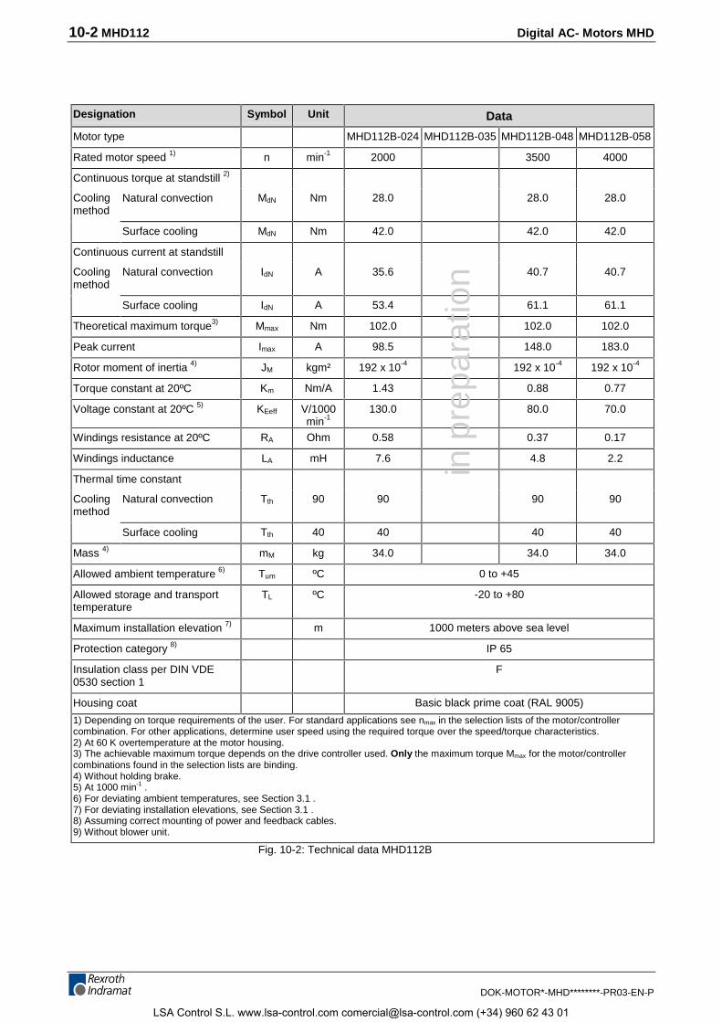
10-2 MHD112 Digital AC- Motors MHD
DOK-MOTOR*-MHD********-PR03-EN-P
Designation Symbol Unit Data
Motor type MHD112B-024 MHD112B-035 MHD112B-048 MHD112B-058
Rated motor speed 1) n min-1 2000 3500 4000
Continuous torque at standstill 2)
Coolingmethod
Natural convection MdN Nm 28.0 28.0 28.0
Surface cooling MdN Nm 42.0 42.0 42.0
Continuous current at standstill
Coolingmethod
Natural convection IdN A 35.6 40.7 40.7
Surface cooling IdN A 53.4 61.1 61.1
Theoretical maximum torque3) Mmax Nm 102.0 102.0 102.0
Peak current Imax A 98.5 148.0 183.0
Rotor moment of inertia 4) JM kgm² 192 x 10-4 192 x 10-4 192 x 10-4
Torque constant at 20ºC Km Nm/A 1.43 0.88 0.77
Voltage constant at 20ºC 5) KEeff V/1000min-1
130.0 80.0 70.0
Windings resistance at 20ºC RA Ohm 0.58 0.37 0.17
Windings inductance LA mH 7.6 4.8 2.2
Thermal time constant
Coolingmethod
Natural convection Tth 90 90 90 90
Surface cooling Tth 40 40 40 40
Mass 4) mM kg 34.0 34.0 34.0
Allowed ambient temperature 6) Tum ºC 0 to +45
Allowed storage and transporttemperature
TL ºC -20 to +80
Maximum installation elevation 7) m 1000 meters above sea level
Protection category 8) IP 65
Insulation class per DIN VDE0530 section 1
F
Housing coat Basic black prime coat (RAL 9005)
1) Depending on torque requirements of the user. For standard applications see nmax in the selection lists of the motor/controllercombination. For other applications, determine user speed using the required torque over the speed/torque characteristics.2) At 60 K overtemperature at the motor housing.3) The achievable maximum torque depends on the drive controller used. Only the maximum torque Mmax for the motor/controllercombinations found in the selection lists are binding.4) Without holding brake.5) At 1000 min-1 .6) For deviating ambient temperatures, see Section 3.1 .7) For deviating installation elevations, see Section 3.1 .8) Assuming correct mounting of power and feedback cables.9) Without blower unit.
Fig. 10-2: Technical data MHD112B
in p
repa
ratio
n
LSA Control S.L. www.lsa-control.com [email protected] (+34) 960 62 43 01
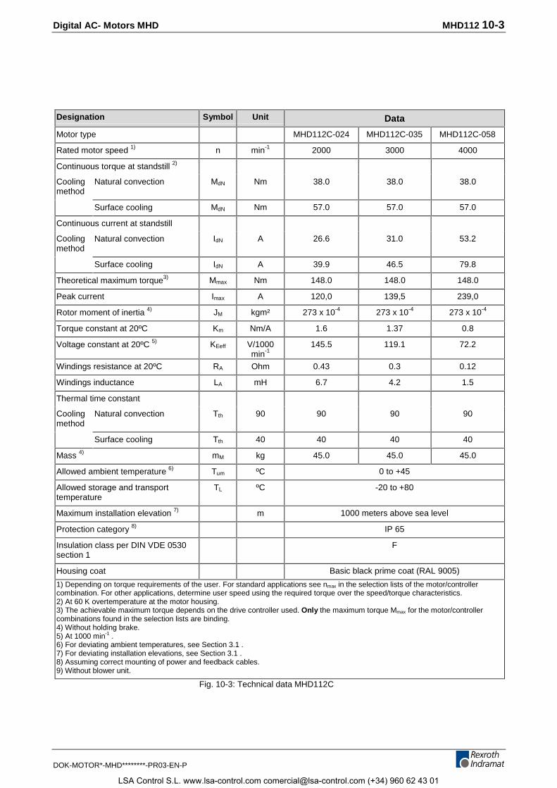
Digital AC- Motors MHD MHD112 10-3
DOK-MOTOR*-MHD********-PR03-EN-P
Designation Symbol Unit Data
Motor type MHD112C-024 MHD112C-035 MHD112C-058
Rated motor speed 1) n min-1 2000 3000 4000
Continuous torque at standstill 2)
Coolingmethod
Natural convection MdN Nm 38.0 38.0 38.0
Surface cooling MdN Nm 57.0 57.0 57.0
Continuous current at standstill
Coolingmethod
Natural convection IdN A 26.6 31.0 53.2
Surface cooling IdN A 39.9 46.5 79.8
Theoretical maximum torque3) Mmax Nm 148.0 148.0 148.0
Peak current Imax A 120,0 139,5 239,0
Rotor moment of inertia 4) JM kgm² 273 x 10-4 273 x 10-4 273 x 10-4
Torque constant at 20ºC Km Nm/A 1.6 1.37 0.8
Voltage constant at 20ºC 5) KEeff V/1000min-1
145.5 119.1 72.2
Windings resistance at 20ºC RA Ohm 0.43 0.3 0.12
Windings inductance LA mH 6.7 4.2 1.5
Thermal time constant
Coolingmethod
Natural convection Tth 90 90 90 90
Surface cooling Tth 40 40 40 40
Mass 4) mM kg 45.0 45.0 45.0
Allowed ambient temperature 6) Tum ºC 0 to +45
Allowed storage and transporttemperature
TL ºC -20 to +80
Maximum installation elevation 7) m 1000 meters above sea level
Protection category 8) IP 65
Insulation class per DIN VDE 0530section 1
F
Housing coat Basic black prime coat (RAL 9005)
1) Depending on torque requirements of the user. For standard applications see nmax in the selection lists of the motor/controllercombination. For other applications, determine user speed using the required torque over the speed/torque characteristics.2) At 60 K overtemperature at the motor housing.3) The achievable maximum torque depends on the drive controller used. Only the maximum torque Mmax for the motor/controllercombinations found in the selection lists are binding.4) Without holding brake.5) At 1000 min-1 .6) For deviating ambient temperatures, see Section 3.1 .7) For deviating installation elevations, see Section 3.1 .8) Assuming correct mounting of power and feedback cables.9) Without blower unit.
Fig. 10-3: Technical data MHD112C
LSA Control S.L. www.lsa-control.com [email protected] (+34) 960 62 43 01
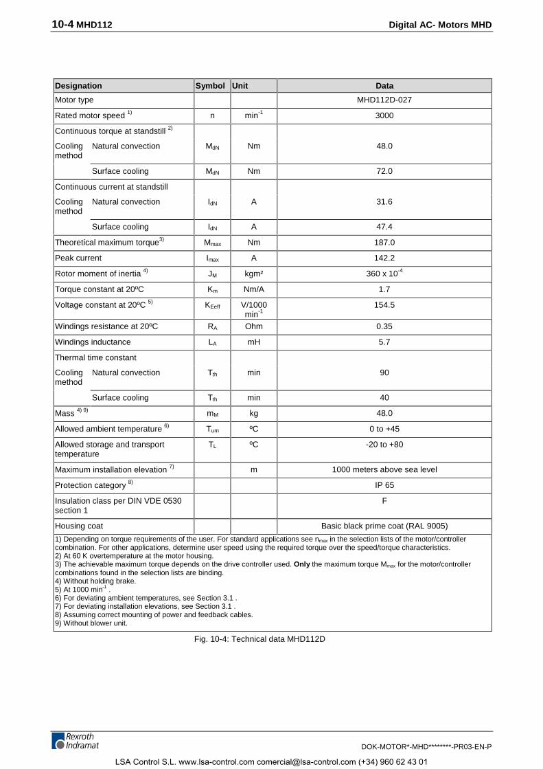
10-4 MHD112 Digital AC- Motors MHD
DOK-MOTOR*-MHD********-PR03-EN-P
Designation Symbol Unit Data
Motor type MHD112D-027
Rated motor speed 1) n min-1 3000
Continuous torque at standstill 2)
Coolingmethod
Natural convection MdN Nm 48.0
Surface cooling MdN Nm 72.0
Continuous current at standstill
Coolingmethod
Natural convection IdN A 31.6
Surface cooling IdN A 47.4
Theoretical maximum torque3) Mmax Nm 187.0
Peak current Imax A 142.2
Rotor moment of inertia 4) JM kgm² 360 x 10-4
Torque constant at 20ºC Km Nm/A 1.7
Voltage constant at 20ºC 5) KEeff V/1000min-1
154.5
Windings resistance at 20ºC RA Ohm 0.35
Windings inductance LA mH 5.7
Thermal time constant
Coolingmethod
Natural convection Tth min 90
Surface cooling Tth min 40
Mass 4) 9) mM kg 48.0
Allowed ambient temperature 6) Tum ºC 0 to +45
Allowed storage and transporttemperature
TL ºC -20 to +80
Maximum installation elevation 7) m 1000 meters above sea level
Protection category 8) IP 65
Insulation class per DIN VDE 0530section 1
F
Housing coat Basic black prime coat (RAL 9005)
1) Depending on torque requirements of the user. For standard applications see nmax in the selection lists of the motor/controllercombination. For other applications, determine user speed using the required torque over the speed/torque characteristics.2) At 60 K overtemperature at the motor housing.3) The achievable maximum torque depends on the drive controller used. Only the maximum torque Mmax for the motor/controllercombinations found in the selection lists are binding.4) Without holding brake.5) At 1000 min-1 .6) For deviating ambient temperatures, see Section 3.1 .7) For deviating installation elevations, see Section 3.1 .8) Assuming correct mounting of power and feedback cables.9) Without blower unit.
Fig. 10-4: Technical data MHD112D
LSA Control S.L. www.lsa-control.com [email protected] (+34) 960 62 43 01
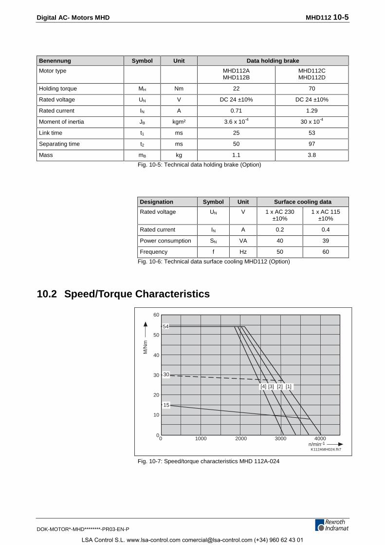
Digital AC- Motors MHD MHD112 10-5
DOK-MOTOR*-MHD********-PR03-EN-P
Benennung Symbol Unit Data holding brake
Motor type MHD112AMHD112B
MHD112CMHD112D
Holding torque MH Nm 22 70
Rated voltage UN V DC 24 ±10% DC 24 ±10%
Rated current IN A 0.71 1.29
Moment of inertia JB kgm² 3.6 x 10⁻⁴ 30 x 10-4
Link time t1 ms 25 53
Separating time t2 ms 50 97
Mass mB kg 1.1 3.8
Fig. 10-5: Technical data holding brake (Option)
Designation Symbol Unit Surface cooling data
Rated voltage UN V 1 x AC 230±10%
1 x AC 115±10%
Rated current IN A 0.2 0.4
Power consumption SN VA 40 39
Frequency f Hz 50 60
Fig. 10-6: Technical data surface cooling MHD112 (Option)
10.2 Speed/Torque Characteristics
Datum der Messung 11.12.99 MKD
22,5
K112AMH024.fh7
10000
2000 30000
10
30
n/min-1
M/N
m
50
4000
20
40
60
15
30
54
[1][2][3][4]
Fig. 10-7: Speed/torque characteristics MHD 112A-024
LSA Control S.L. www.lsa-control.com [email protected] (+34) 960 62 43 01
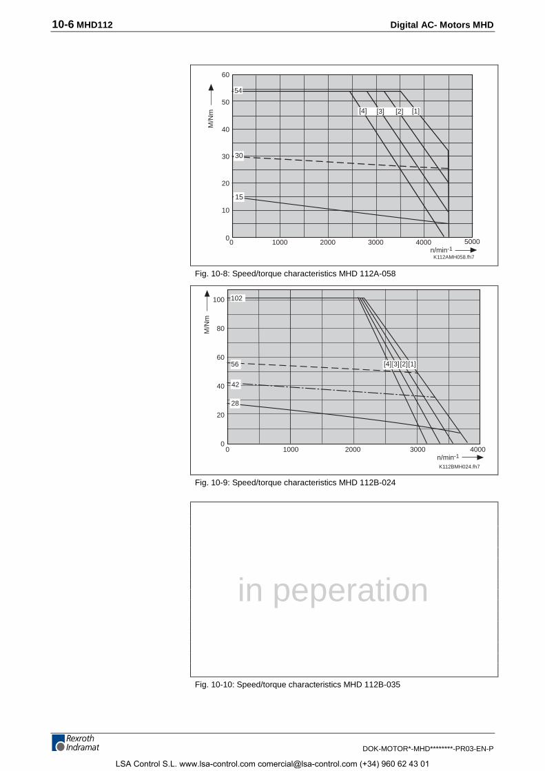
10-6 MHD112 Digital AC- Motors MHD
DOK-MOTOR*-MHD********-PR03-EN-P
Datum der Messung 25.06.99
K112AMH058.fh7
22,5
10000
2000 30000
10
30
n/min-1
M/N
m
50
4000
20
40
60
15
30
54
5000
[1][2][3][4]
Fig. 10-8: Speed/torque characteristics MHD 112A-058
Datum der messung 16.12.97
K112BMH024.fh7
1000 2000 30000n/min-1
M/N
m
4000
102
28
42
56 [1][2][3]
100
80
60
40
20
0
[4]
Fig. 10-9: Speed/torque characteristics MHD 112B-024
Fig. 10-10: Speed/torque characteristics MHD 112B-035
in peperation
LSA Control S.L. www.lsa-control.com [email protected] (+34) 960 62 43 01
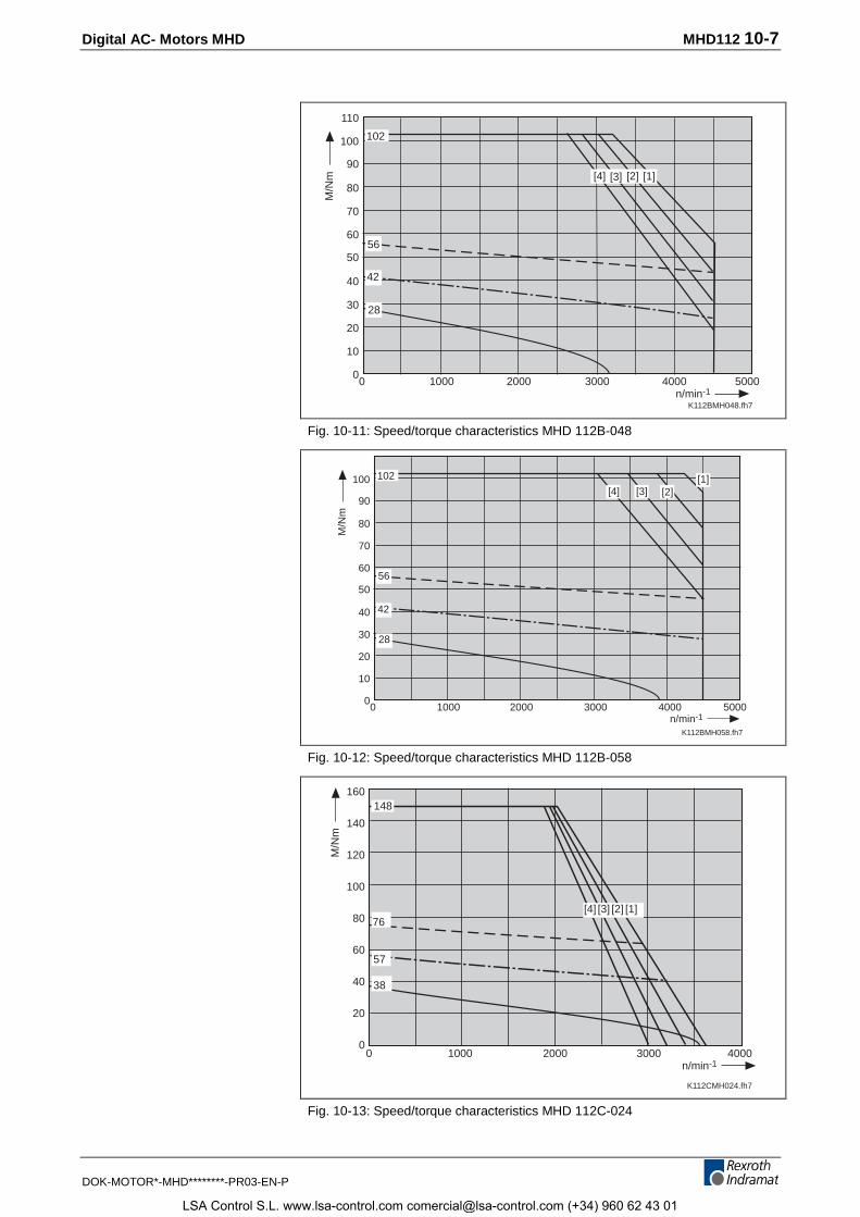
Digital AC- Motors MHD MHD112 10-7
DOK-MOTOR*-MHD********-PR03-EN-P
K112BMH048.fh7
10000
2000 30000
10
90
70
30
n/min-1
M/N
m
50
4000 5000
56
102
20
40
60
80
100
42
[1][2][3][4]
110
28
Fig. 10-11: Speed/torque characteristics MHD 112B-048
Datum der Messung 99-08-12
K112BMH058.fh7
10000
2000 30000
10
90
70
30
n/min-1
M/N
m
50
4000 5000
20
40
60
80
100[2][3][4]
102
56
42
28
[1]
Fig. 10-12: Speed/torque characteristics MHD 112B-058
K112CMH024.fh7
1000 2000 30000n/min-1
M/N
m
4000
160
140
120
100
80
60
40
20
0
[4] [3] [2] [1]
148
76
57
38
Fig. 10-13: Speed/torque characteristics MHD 112C-024
LSA Control S.L. www.lsa-control.com [email protected] (+34) 960 62 43 01
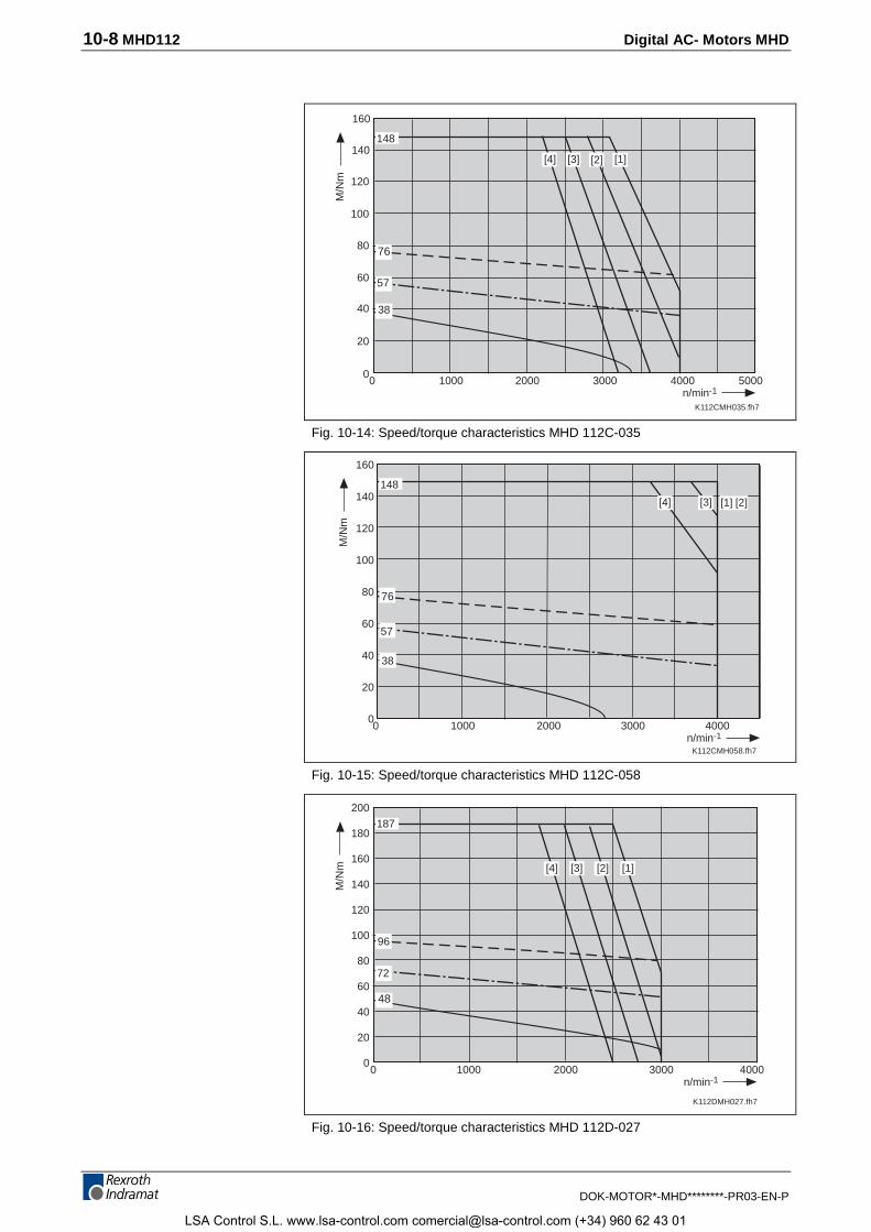
10-8 MHD112 Digital AC- Motors MHD
DOK-MOTOR*-MHD********-PR03-EN-P
Datum der Messung: 30.06.99
K112CMH035.fh7
10000
2000 30000n/min-1
M/N
m
4000 5000
20
40
60
80
100
[2][3][4]
148
76
57
38
[1]
120
140
160
Fig. 10-14: Speed/torque characteristics MHD 112C-035
K112CMH058.fh7
1000 2000 30000n/min-1
M/N
m
4000
[2][4]
148
76
57
38
[1]
160
140
120
100
80
60
40
20
0
[3]
Fig. 10-15: Speed/torque characteristics MHD 112C-058
Datum der Messung 15.06.99
K112DMH027.fh7
1000 2000 30000n/min-1
M/N
m
4000
[4]
187
96
72
48
[1]
200
180
160
140
120
100
80
60
40
20
0
[2][3]
Fig. 10-16: Speed/torque characteristics MHD 112D-027
LSA Control S.L. www.lsa-control.com [email protected] (+34) 960 62 43 01
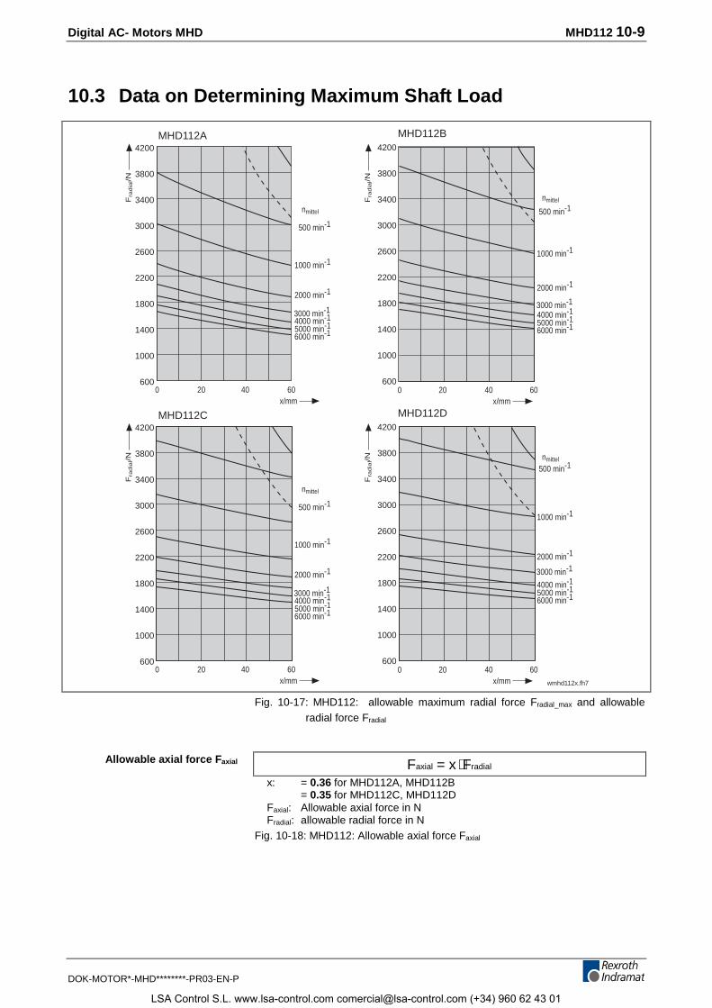
Digital AC- Motors MHD MHD112 10-9
DOK-MOTOR*-MHD********-PR03-EN-P
10.3 Data on Determining Maximum Shaft Load
20 40 60x/mm
nmittel
500 min-1
1000 min-1
2000 min-1
3000 min-14000 min-1
6000 min-1
Fra
dia
l/N
5000 min-1
0 20 40 60x/mm
nmittel
500 min-1
1000 min-1
2000 min-1
3000 min-1
4000 min-1
6000 min-1
Fra
dia
l/N
5000 min-1
0
20 40 60x/mm
nmittel
500 min-1
1000 min-1
2000 min-1
3000 min-14000 min-1
6000 min-1
Fra
dia
l/N
5000 min-1
0 20 40 60x/mm
nmittel
500 min-1
1000 min-1
2000 min-1
3000 min-1
4000 min-1
6000 min-1
Fra
dia
l/N
5000 min-1
0
MHD112A MHD112B
wmhd112x.fh7
4200
3800
3400
3000
2600
2200
1800
1400
1000
600
4200
3800
3400
3000
2600
2200
1800
1400
1000
600
MHD112C MHD112D4200
3800
3400
3000
2600
2200
1800
1400
1000
600
4200
3800
3400
3000
2600
2200
1800
1400
1000
600
Fig. 10-17: MHD112: allowable maximum radial force Fradial_max and allowableradial force Fradial
F x Faxial radial= ⋅x: = 0.36 for MHD112A, MHD112B
= 0.35 for MHD112C, MHD112DFaxial: Allowable axial force in NFradial: allowable radial force in N
Fig. 10-18: MHD112: Allowable axial force Faxial
Allowable axial force Faxial
LSA Control S.L. www.lsa-control.com [email protected] (+34) 960 62 43 01
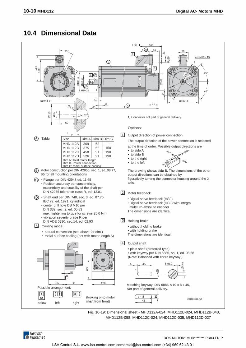
10-10 MHD112 Digital AC- Motors MHD
DOK-MOTOR*-MHD********-PR03-EN-P
10.4 Dimensional Data
C • Flange per DIN 42948,ed. 11.65• Position accuracy per concentricity, excentricity and coaxility of the shaft per DIN 42955 tolerance class R, ed. 12.81
D • Shaft end per DIN 748, sec. 3, ed. 07.75, IEC 72, ed. 1971, cylindrical• center drill hole DS M10 per DIN 332, sec. 2, ed. 05.83 max. tightening torque for screws 25,0 Nm• vibration severity grade R per DIN VDE 0530, sec.14, ed. 02.93
M01MH112.fh7
45 5+0,2
10 N
9
Options:
Holding brake:
• without holding brake• with holding brakeThe dimensions are identical.
4
Output direction of power connection
The output direction of the power connection is selected
at the time of order. Possible output directions are• to side A• to side B• to the right• to the left
The drawing shows side B. The dimensions of the otheroutput directions can be obtained byfiguratively turning the connector housing around the Xaxis.
2
1
3
4
45
10t = 8
Motor feedback
• Digital servo feedback (HSF)• Digital servo feedback (HSF) with integral multiturn-absolute encoderThe dimensions are identical.
Matching keyway: DIN 6885-A 10 x 8 x 45,Not part of general delivery.
Output shaft
• plain shaft (preferred type)• with keyway per DIN 6885, sh. 1, ed. 08.68(Note: Balanced with entire keyway!)
1) Connector not part of generel delivery.
25°
13916
4
Ø13
0 j6
Ø32
k6
M10-22D
C4
Y
163
B
X
58A581)
A18
6071
A
4 192±1
45°
45°
4 x M10 - 15
Pg2
9
Table SizeMHD 112AMHD 112BMHD 112CMHD 112DDim A: Total motor lengthDim B. Power connectionDim C: radial surface cooling
Dim A309375458526
Dim B62629191
Dim C---
150190190
B Motor construction per DIN 42950, sec. 1, ed. 08.77,B5 for all mounting orientations
below left right
Possible arrangement:
(looking onto motorshaft from front)
156 220
190
33
Cooling mode:
• natural convection (see above for dim.)• radial surface cooling (not with motor length A)
5
C
A-Side
B-Sideleft
right
122
2
3
5 Ø10
714
Detail Y:
Ø40
Ø11
0
R1,6
1x15º
60
4
A
B
1
165±0,2
245
215
Fig. 10-19: Dimensional sheet - MHD112A-024, MHD112B-024, MHD112B-048,MHD112B-058, MHD112C-024, MHD112C-035, MHD112D-027
LSA Control S.L. www.lsa-control.com [email protected] (+34) 960 62 43 01
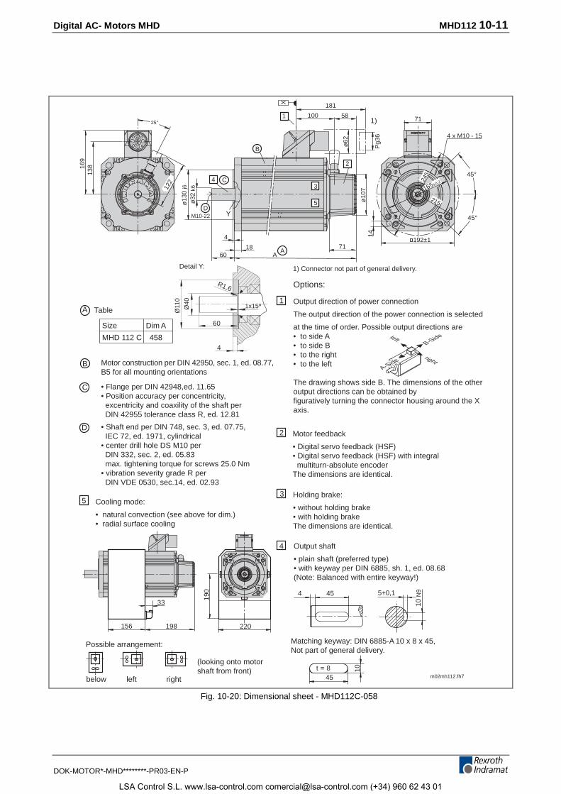
Digital AC- Motors MHD MHD112 10-11
DOK-MOTOR*-MHD********-PR03-EN-P
C4
Y
B
2
3
5
25°
13816
9
122
R1,6
60
4
Detail Y:
Ø40 1x15º
Ø11
0
m02mh112.fh7
C
D
B Motor construction per DIN 42950, sec. 1, ed. 08.77,B5 for all mounting orientations
• Flange per DIN 42948,ed. 11.65• Position accuracy per concentricity, excentricity and coaxility of the shaft per DIN 42955 tolerance class R, ed. 12.81
• Shaft end per DIN 748, sec. 3, ed. 07.75, IEC 72, ed. 1971, cylindrical• center drill hole DS M10 per DIN 332, sec. 2, ed. 05.83 max. tightening torque for screws 25.0 Nm• vibration severity grade R per DIN VDE 0530, sec.14, ed. 02.93
1) Connector not part of general delivery.
below left right
Possible arrangement:
(looking onto motorshaft from front)
Cooling mode:
• natural convection (see above for dim.)• radial surface cooling
5
Table
Size Dim A
MHD 112 C 458
A
45 5+0,1
10 N
9
Options:
Holding brake:
• without holding brake• with holding brakeThe dimensions are identical.
4
Output direction of power connection
The output direction of the power connection is selected
at the time of order. Possible output directions are• to side A• to side B• to the right• to the left
The drawing shows side B. The dimensions of the otheroutput directions can be obtained byfiguratively turning the connector housing around the Xaxis.
2
1
3
4
45
10t = 8
Motor feedback
• Digital servo feedback (HSF)• Digital servo feedback (HSF) with integral multiturn-absolute encoderThe dimensions are identical.
Matching keyway: DIN 6885-A 10 x 8 x 45,Not part of general delivery.
Output shaft
• plain shaft (preferred type)• with keyway per DIN 6885, sh. 1, ed. 08.68(Note: Balanced with entire keyway!)
156 220
190
33
198
ø13
0 j6
ø32
k6
M10-22D
181
1001
X
581)
ø10
7
1860
71A
A
4
ø62
Pg3
6
71
45°
45°
14
192±1
4 x M10 - 15
165±0,2245
215
A-Side
B-Sideleft
right
Fig. 10-20: Dimensional sheet - MHD112C-058
LSA Control S.L. www.lsa-control.com [email protected] (+34) 960 62 43 01
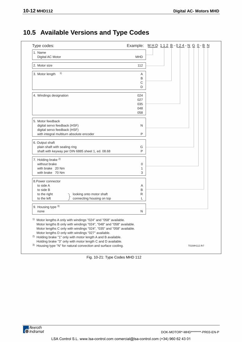
10-12 MHD112 Digital AC- Motors MHD
DOK-MOTOR*-MHD********-PR03-EN-P
10.5 Available Versions and Type Codes
1. NameDigital AC Motor MHD
2. Motor size 112
3. Motor length 1) ABCD
4. Windings designation 024027035048058
5. Motor feedbackdigital servo feedback (HSF) Ndigital servo feedback (HSF)with integral multiturn absolute encoder P
6. Output shaftplain shaft with sealing ring Gshaft with keyway per DIN 6885 sheet 1, ed. 08.68 P
7. Holding brake 2)
without brake 0with brake 20 Nm 1with brake 70 Nm 3
8.Power connectorto side A Ato side B Bto the right looking onto motor shaft Rto the left connecting housing on top L
9. Housing type 3)
none N
Type codes: Example: M H D 1 1 2 B - 0 2 4 - N G 0 - B N
T01MH112.fh7
1) Motor lengths A only with windings "024" and "058" available. Motor lengths B only with windings "024", "048" and "058" available. Motor lengths C only with windings "024", "035" and "058" available.
Motor lengths D only with windings "027" available.2) Holding brake "1" only with motor length A and B available.
Holding brake "3" only with motor length C and D available.3) Housing type "N" for natural convection and surface cooling.
Fig. 10-21: Type Codes MHD 112
LSA Control S.L. www.lsa-control.com [email protected] (+34) 960 62 43 01
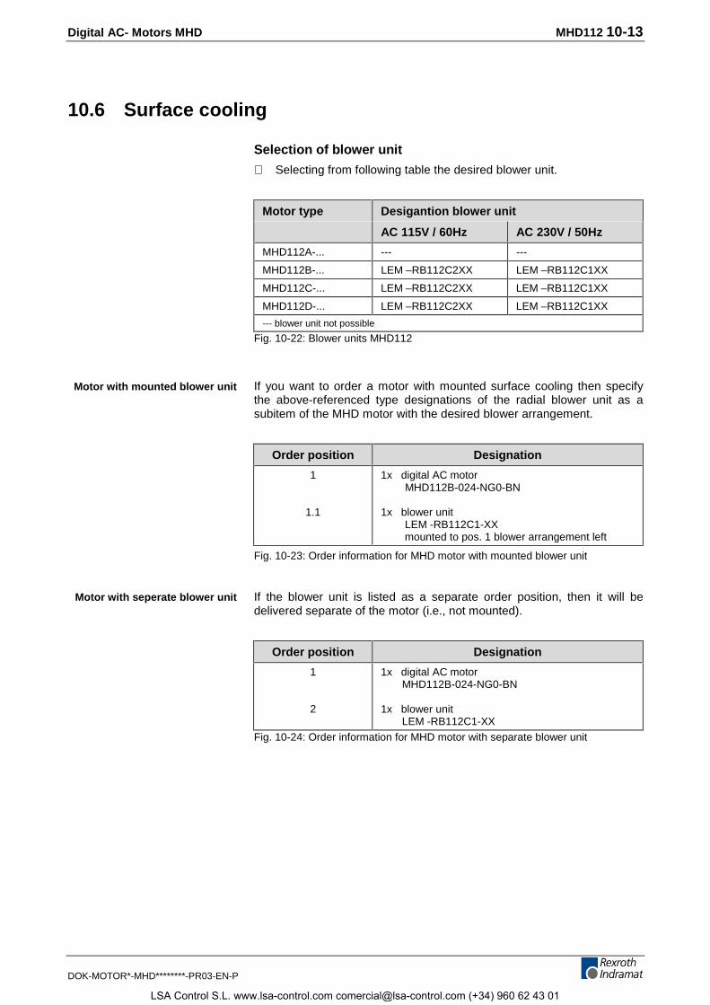
Digital AC- Motors MHD MHD112 10-13
DOK-MOTOR*-MHD********-PR03-EN-P
10.6 Surface cooling
Selection of blower unit
⇒ Selecting from following table the desired blower unit.
Motor type Desigantion blower unit
AC 115V / 60Hz AC 230V / 50Hz
MHD112A-... --- ---
MHD112B-... LEM –RB112C2XX LEM –RB112C1XX
MHD112C-... LEM –RB112C2XX LEM –RB112C1XX
MHD112D-... LEM –RB112C2XX LEM –RB112C1XX
--- blower unit not possible
Fig. 10-22: Blower units MHD112
If you want to order a motor with mounted surface cooling then specifythe above-referenced type designations of the radial blower unit as asubitem of the MHD motor with the desired blower arrangement.
Order position Designation
1
1.1
1x digital AC motor MHD112B-024-NG0-BN
1x blower unit LEM -RB112C1-XX mounted to pos. 1 blower arrangement left
Fig. 10-23: Order information for MHD motor with mounted blower unit
If the blower unit is listed as a separate order position, then it will bedelivered separate of the motor (i.e., not mounted).
Order position Designation
1
2
1x digital AC motor MHD112B-024-NG0-BN
1x blower unit LEM -RB112C1-XX
Fig. 10-24: Order information for MHD motor with separate blower unit
Motor with mounted blower unit
Motor with seperate blower unit
LSA Control S.L. www.lsa-control.com [email protected] (+34) 960 62 43 01

10-14 MHD112 Digital AC- Motors MHD
DOK-MOTOR*-MHD********-PR03-EN-P
LSA Control S.L. www.lsa-control.com [email protected] (+34) 960 62 43 01
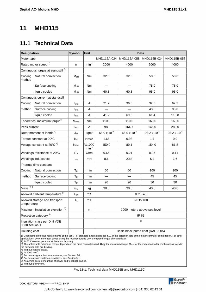
Digital AC- Motors MHD MHD115 11-1
DOK-MOTOR*-MHD********-PR03-EN-P
11 MHD115
11.1 Technical Data
Designation Symbol Unit Data
Motor type MHD115A-024 MHD115A-058 MHD115B-024 MHD115B-058
Rated motor speed 1) n min-1 2000 4000 2000 4000
Continuous torque at standstill 2)
Coolingmethod
Natural convection MdN Nm 32.0 32.0 50.0 50.0
Surface cooling MdN Nm --- --- 75.0 75.0
liquid cooled MdN Nm 60.8 60.8 95.0 95.0
Continuous current at standstill
Cooling Natural convection IdN A 21.7 36.6 32.3 62.2
method Surface cooling IdN A --- --- 48.5 93.8
liquid cooled IdN A 41.2 69.5 61.4 118.8
Theoretical maximum torque3) Mmax Nm 110.0 110.0 160.0 160.0
Peak current Imax A 98. 164.7 145.0 280.0
Rotor moment of inertia 4) JM kgm² 65,0 x 10⁻⁴ 65,0 x 10⁻⁴ 93,2 x 10⁻⁴ 93,2 x 10⁻⁴
Torque constant at 20ºC Km Nm/A 1.65 0.98 1.7 0.9
Voltage constant at 20ºC 5) KEeff V/1000min-1
150.0 89.1 154.0 81.8
Windings resistance at 20ºC RA Ohm 0.66 0.21 0.36 0.11
Windings inductance LA mH 8.6 2.88 5.3 1.6
Thermal time constant
Cooling Natural convection Tth min 60 60 100 100
method Surface cooling Tth min --- --- 45 45
liquid cooled Tth min 20 20 30 30
Mass 4) 9) mM kg 30.0 30.0 40.0 40.0
Allowed ambient temperature 6) Tum ºC 0 to +45
Allowed storage and transporttemperature
TL ºC -20 to +80
Maximum installation elevation 7) m 1000 meters above sea level
Protection category 8) IP 65
Insulation class per DIN VDE0530 section 1
F
Housing coat Basic black prime coat (RAL 9005)
1) Depending on torque requirements of the user. For standard applications see nmax in the selection lists of the motor/controller combination. For otherapplications, determine user speed using the required torque over the speed/torque characteristics.2) At 60 K overtemperature at the motor housing.3) The achievable maximum torque depends on the drive controller used. Only the maximum torque Mmax for the motor/controller combinations found inthe selection lists are binding.4) Without holding brake.5) At 1000 min-1 .6) For deviating ambient temperatures, see Section 3-1 .7) For deviating installation elevations, see Section 3-1 .8) Assuming correct mounting of power and feedback cables.9) Without blower unit.
Fig. 11-1: Technical data MHD115B and MHD115C
LSA Control S.L. www.lsa-control.com [email protected] (+34) 960 62 43 01
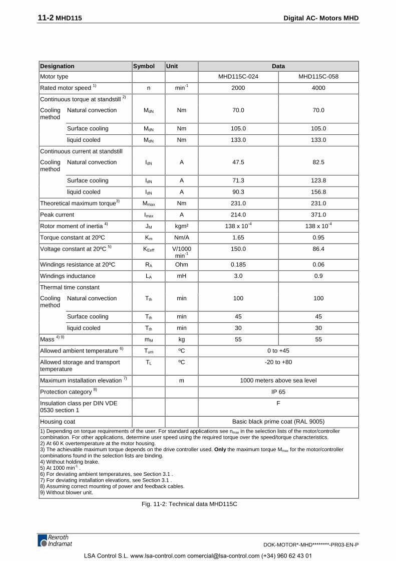
11-2 MHD115 Digital AC- Motors MHD
DOK-MOTOR*-MHD********-PR03-EN-P
Designation Symbol Unit Data
Motor type MHD115C-024 MHD115C-058
Rated motor speed 1) n min-1 2000 4000
Continuous torque at standstill 2)
Coolingmethod
Natural convection MdN Nm 70.0 70.0
Surface cooling MdN Nm 105.0 105.0
liquid cooled MdN Nm 133.0 133.0
Continuous current at standstill
Coolingmethod
Natural convection IdN A 47.5 82.5
Surface cooling IdN A 71.3 123.8
liquid cooled IdN A 90.3 156.8
Theoretical maximum torque3) Mmax Nm 231.0 231.0
Peak current Imax A 214.0 371.0
Rotor moment of inertia 4) JM kgm² 138 x 10-4 138 x 10-4
Torque constant at 20ºC Km Nm/A 1.65 0.95
Voltage constant at 20ºC 5) KEeff V/1000min-1
150.0 86.4
Windings resistance at 20ºC RA Ohm 0.185 0.06
Windings inductance LA mH 3.0 0.9
Thermal time constant
Coolingmethod
Natural convection Tth min 100 100
Surface cooling Tth min 45 45
liquid cooled Tth min 30 30
Mass 4) 9) mM kg 55 55
Allowed ambient temperature 6) Tum ºC 0 to +45
Allowed storage and transporttemperature
TL ºC -20 to +80
Maximum installation elevation 7) m 1000 meters above sea level
Protection category 8) IP 65
Insulation class per DIN VDE0530 section 1
F
Housing coat Basic black prime coat (RAL 9005)
1) Depending on torque requirements of the user. For standard applications see nmax in the selection lists of the motor/controllercombination. For other applications, determine user speed using the required torque over the speed/torque characteristics.2) At 60 K overtemperature at the motor housing.3) The achievable maximum torque depends on the drive controller used. Only the maximum torque Mmax for the motor/controllercombinations found in the selection lists are binding.4) Without holding brake.5) At 1000 min-1 .6) For deviating ambient temperatures, see Section 3.1 .7) For deviating installation elevations, see Section 3.1 .8) Assuming correct mounting of power and feedback cables.9) Without blower unit.
Fig. 11-2: Technical data MHD115C
LSA Control S.L. www.lsa-control.com [email protected] (+34) 960 62 43 01
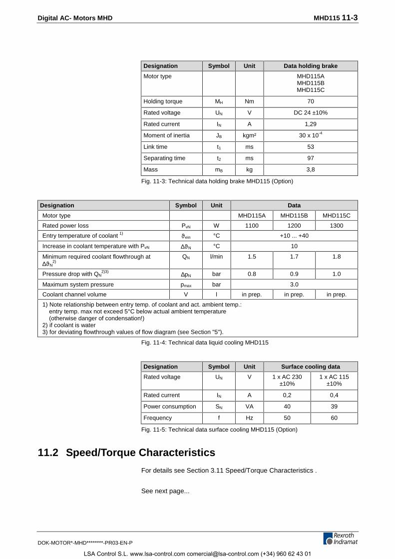
Digital AC- Motors MHD MHD115 11-3
DOK-MOTOR*-MHD********-PR03-EN-P
Designation Symbol Unit Data holding brake
Motor type MHD115AMHD115BMHD115C
Holding torque MH Nm 70
Rated voltage UN V DC 24 ±10%
Rated current IN A 1,29
Moment of inertia JB kgm² 30 x 10-4
Link time t1 ms 53
Separating time t2 ms 97
Mass mB kg 3,8
Fig. 11-3: Technical data holding brake MHD115 (Option)
Designation Symbol Unit Data
Motor type MHD115A MHD115B MHD115C
Rated power loss PvN W 1100 1200 1300
Entry temperature of coolant 1) ϑein °C +10 ... +40
Increase in coolant temperature with PvN ∆ϑN °C 10
Minimum required coolant flowthrough at∆ϑN
2)QN l/min 1.5 1.7 1.8
Pressure drop with QN2)3) ∆pN bar 0.8 0.9 1.0
Maximum system pressure pmax bar 3.0
Coolant channel volume V l in prep. in prep. in prep.
1) Note relationship between entry temp. of coolant and act. ambient temp.: entry temp. max not exceed 5°C below actual ambient temperature (otherwise danger of condensation!)2) if coolant is water3) for deviating flowthrough values of flow diagram (see Section "5").
Fig. 11-4: Technical data liquid cooling MHD115
Designation Symbol Unit Surface cooling data
Rated voltage UN V 1 x AC 230±10%
1 x AC 115±10%
Rated current IN A 0,2 0,4
Power consumption SN VA 40 39
Frequency f Hz 50 60
Fig. 11-5: Technical data surface cooling MHD115 (Option)
11.2 Speed/Torque Characteristics
For details see Section 3.11 Speed/Torque Characteristics .
See next page...
LSA Control S.L. www.lsa-control.com [email protected] (+34) 960 62 43 01
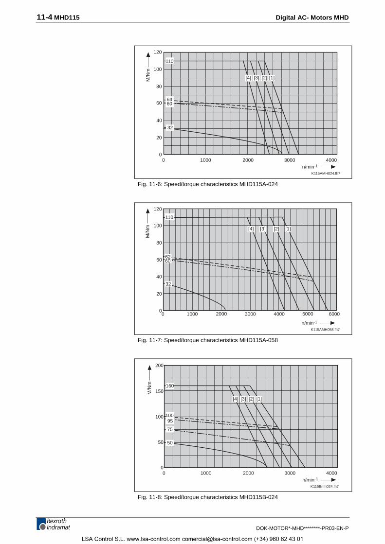
11-4 MHD115 Digital AC- Motors MHD
DOK-MOTOR*-MHD********-PR03-EN-P
K115AMH024.fh7
10000
2000 3000 40000
20
40
80
60
n/min-1
M/N
m 100
120
110
6460
32
[1][2][3][4]
Fig. 11-6: Speed/torque characteristics MHD115A-024
45
K115AMH058.fh7
10000
3000 4000 60000
20
40
80
60
n/min-1
M/N
m 100[2][3][4]
120
110
32
6260
2000 5000
[1]
Fig. 11-7: Speed/torque characteristics MHD115A-058
K115Bmh024.fh7
10000
2000 3000 40000
50
100
n/min-1
M/N
m
150
[1][2][3]
200
[4]
160
10095
75
50
Fig. 11-8: Speed/torque characteristics MHD115B-024
LSA Control S.L. www.lsa-control.com [email protected] (+34) 960 62 43 01
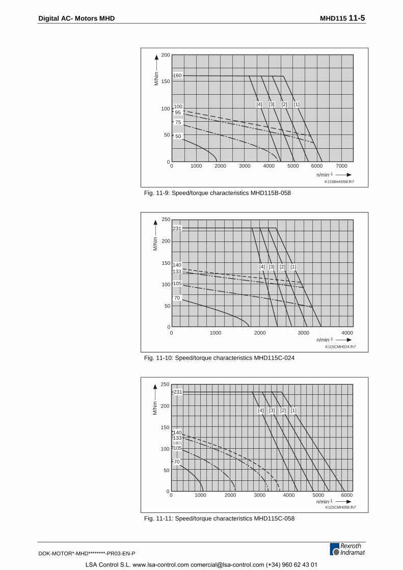
Digital AC- Motors MHD MHD115 11-5
DOK-MOTOR*-MHD********-PR03-EN-P
K115Bmh058.fh7
10000
3000 60000
50
100
n/min-1
M/N
m
150
[2][3]
200
[4]
75
50
100 [1]
160
2000 4000 5000 7000
95
Fig. 11-9: Speed/torque characteristics MHD115B-058
K115CMH024.fh7
10000
2000 3000 40000
50
100
n/min-1
M/N
m
150[2][3][4]
200
250
140133
70
105
231
[1]
Fig. 11-10: Speed/torque characteristics MHD115C-024
K115CMH058.fh7
20000
3000 5000 60000
50
100
n/min-1
M/N
m
150
[1][2]200
250
[4]
231
105
140133
70
1000 4000
[3]
Fig. 11-11: Speed/torque characteristics MHD115C-058
LSA Control S.L. www.lsa-control.com [email protected] (+34) 960 62 43 01
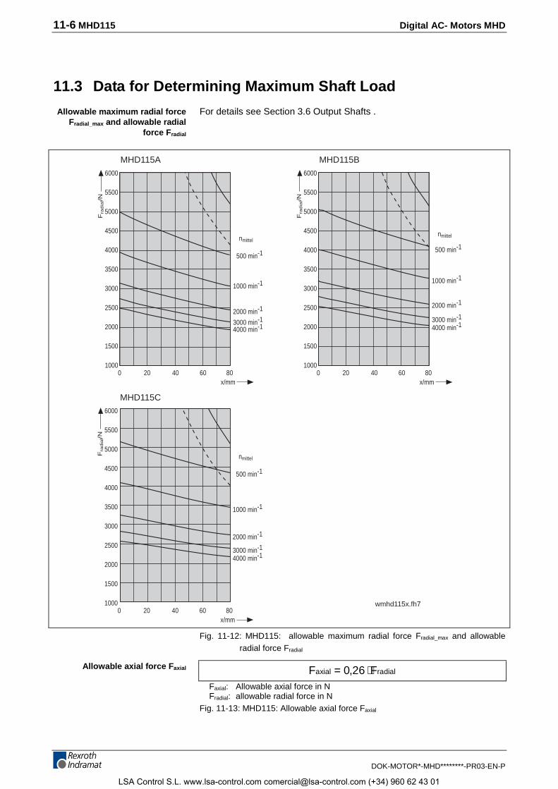
11-6 MHD115 Digital AC- Motors MHD
DOK-MOTOR*-MHD********-PR03-EN-P
11.3 Data for Determining Maximum Shaft Load
For details see Section 3.6 Output Shafts .
20x/mm
nmittel
500 min-1
1000 min-1
2000 min-1
3000 min-1
4000 min-1
Fra
dia
l/N
0
6000
5500
5000
4500
4000
3500
3000
2500
2000
1500
100040 60 80
20x/mm
nmittel
500 min-1
1000 min-1
2000 min-1
3000 min-1
4000 min-1
Fra
dia
l/N
0
6000
5500
5000
4500
4000
3500
3000
2500
2000
1500
100040 60 80
wmhd115x.fh7
20x/mm
nmittel
500 min-1
1000 min-1
2000 min-1
3000 min-14000 min-1
Fra
dia
l/N
0
6000
5500
5000
4500
4000
3500
3000
2500
2000
1500
100040 60 80
MHD115A MHD115B
MHD115C
Fig. 11-12: MHD115: allowable maximum radial force Fradial_max and allowableradial force Fradial
F Faxial radial= ⋅0 26,Faxial: Allowable axial force in NFradial: allowable radial force in N
Fig. 11-13: MHD115: Allowable axial force Faxial
Allowable maximum radial forceFradial_max and allowable radial
force Fradial
Allowable axial force Faxial
LSA Control S.L. www.lsa-control.com [email protected] (+34) 960 62 43 01
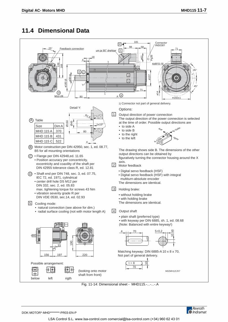
Digital AC- Motors MHD MHD115 11-7
DOK-MOTOR*-MHD********-PR03-EN-P
11.4 Dimensional Data
M02MH115.fh7
70 5+0,2
10 N
9
Options:
Holding brake:
• without holding brake• with holding brakeThe dimensions are identical.
4
Output direction of power connectionThe output direction of the power connection is selectedat the time of order. Possible output directions are• to side A• to side B• to the right• to the left
The drawing shows side B. The dimensions of the otheroutput directions can be obtained byfiguratively turning the connector housing around the Xaxis.
2
1
3
4
70
10t = 8
C
D
B
Motor feedback
• Digital servo feedback (HSF)• Digital servo feedback (HSF) with integral multiturn-absolute encoderThe dimensions are identical.
Matching keyway: DIN 6885-A 10 x 8 x 70,Not part of general delivery.
Output shaft
• plain shaft (preferred type)• with keyway per DIN 6885, sh. 1, ed. 08.68(Note: Balanced with entire keyway!)
Motor construction per DIN 42950, sec. 1, ed. 08.77,B5 for all mounting orientations
• Flange per DIN 42948,ed. 11.65• Position accuracy per concentricity, excentricity and coaxility of the shaft per DIN 42955 tolerance class R, ed. 12.81
• Shaft end per DIN 748, sec. 3, ed. 07.75, IEC 72, ed. 1971, cylindrical• center drill hole DS M12 per DIN 332, sec. 2, ed. 05.83 max. tightening torque for screws 43 Nm• vibration severity grade R per DIN VDE 0530, sec.14, ed. 02.93
below left rigth
Possible arrangement:
(looking onto motorshaft from front)
Cooling mode:• natural convection (see above for dim.)• radial surface cooling (not with motor length A)
5
Size Dim A
MHD 115 A 370
MHD 115 B 431
MHD 115 C 522 4
156 220
190
33
197
1) Connector not part of general delivery.
um je 90° drehbar
ConnectorINS0381
ø38
k6
ø18
0 j6
A
181
981
58
1)
A
X
3
5
ø10
7
71
C4
Y
418
80
ø62
45°
45°
192±1
ø215
ø245
ø165
4xM10-16
ø14
7112
2
139
168
25°
Pg3
6
DM12-28
A-Side
B-Sideleft
right
Detail Y:
Ø45
Ø15
0
R1,6
1x15º
80
Feedback connection
TableA
Fig. 11-14: Dimensional sheet - MHD115.-...-...-.A
LSA Control S.L. www.lsa-control.com [email protected] (+34) 960 62 43 01
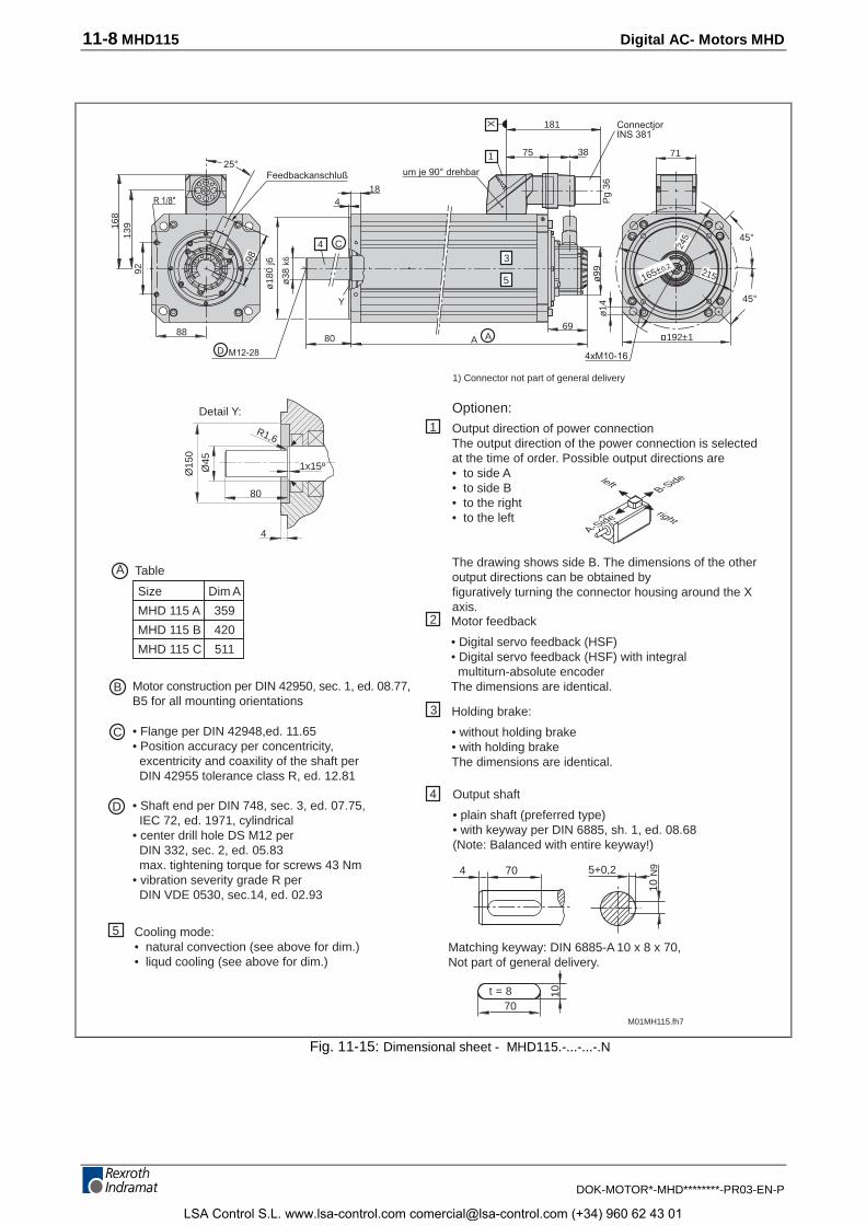
11-8 MHD115 Digital AC- Motors MHD
DOK-MOTOR*-MHD********-PR03-EN-P
M01MH115.fh7
70 5+0,2
10 N
9
Optionen:
Holding brake:
• without holding brake• with holding brakeThe dimensions are identical.
4
Output direction of power connectionThe output direction of the power connection is selectedat the time of order. Possible output directions are• to side A• to side B• to the right• to the left
The drawing shows side B. The dimensions of the otheroutput directions can be obtained byfiguratively turning the connector housing around the Xaxis.
2
1
3
4
70
10t = 8
C
D
B
Motor feedback
• Digital servo feedback (HSF)• Digital servo feedback (HSF) with integral multiturn-absolute encoderThe dimensions are identical.
Matching keyway: DIN 6885-A 10 x 8 x 70,Not part of general delivery.
Output shaft
• plain shaft (preferred type)• with keyway per DIN 6885, sh. 1, ed. 08.68(Note: Balanced with entire keyway!)
Motor construction per DIN 42950, sec. 1, ed. 08.77,B5 for all mounting orientations
• Flange per DIN 42948,ed. 11.65• Position accuracy per concentricity, excentricity and coaxility of the shaft per DIN 42955 tolerance class R, ed. 12.81
• Shaft end per DIN 748, sec. 3, ed. 07.75, IEC 72, ed. 1971, cylindrical• center drill hole DS M12 per DIN 332, sec. 2, ed. 05.83 max. tightening torque for screws 43 Nm• vibration severity grade R per DIN VDE 0530, sec.14, ed. 02.93
Cooling mode:• natural convection (see above for dim.)• liqud cooling (see above for dim.)
5
Size Dim A
MHD 115 A 359
MHD 115 B 420
MHD 115 C 511
13916
8
92
R 1/8"
Feedbackanschluß25°
M12-28
um je 90° drehbar
ConnectjorINS 381
4xM10-16
ø38
k6
C4
Y
98
88
ø18
0 j6
418
8069
A
181
751
X
38
1)
Pg
36ø
99
A
71
45°
45°
ø14
192±1
1) Connector not part of general delivery
3
5
D
4 A-Side
B-Sideleft
right
Detail Y:
Ø45
Ø15
0
R1,6
1x15º
80
TableA
165±0,2
98
215
245
Fig. 11-15: Dimensional sheet - MHD115.-...-...-.N
LSA Control S.L. www.lsa-control.com [email protected] (+34) 960 62 43 01
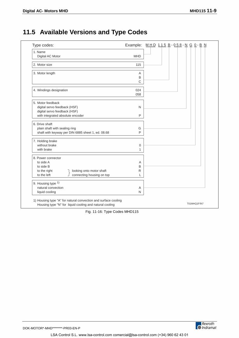
Digital AC- Motors MHD MHD115 11-9
DOK-MOTOR*-MHD********-PR03-EN-P
11.5 Available Versions and Type Codes
1. NameDigital AC Motor MHD
2. Motor size 115
3. Motor length AB
C
4. Windings designation 024058
5. Motor feedbackdigital servo feedback (HSF) Ndigital servo feedback (HSF)
with integrated absolute encoder P
6. Drive shaftplain shaft with sealing ring Gshaft with keyway per DIN 6885 sheet 1, ed. 08.68 P
7. Holding brakewithout brake 0with brake 1
8. Power connectorto side A Ato side B Bto the right looking onto motor shaft Rto the left connecting housing on top L
9. Housing type 1)
natural convection Aliquid cooling N
1) Housing type "A" for natural convection and surface coolingHousing type "N" for liquid cooling and natural cooling
Type codes: Example: M H D 1 1 5 B - 0 5 8 - N G 0 - B N
T01MHQ1P.fh7
Fig. 11-16: Type Codes MHD115
LSA Control S.L. www.lsa-control.com [email protected] (+34) 960 62 43 01
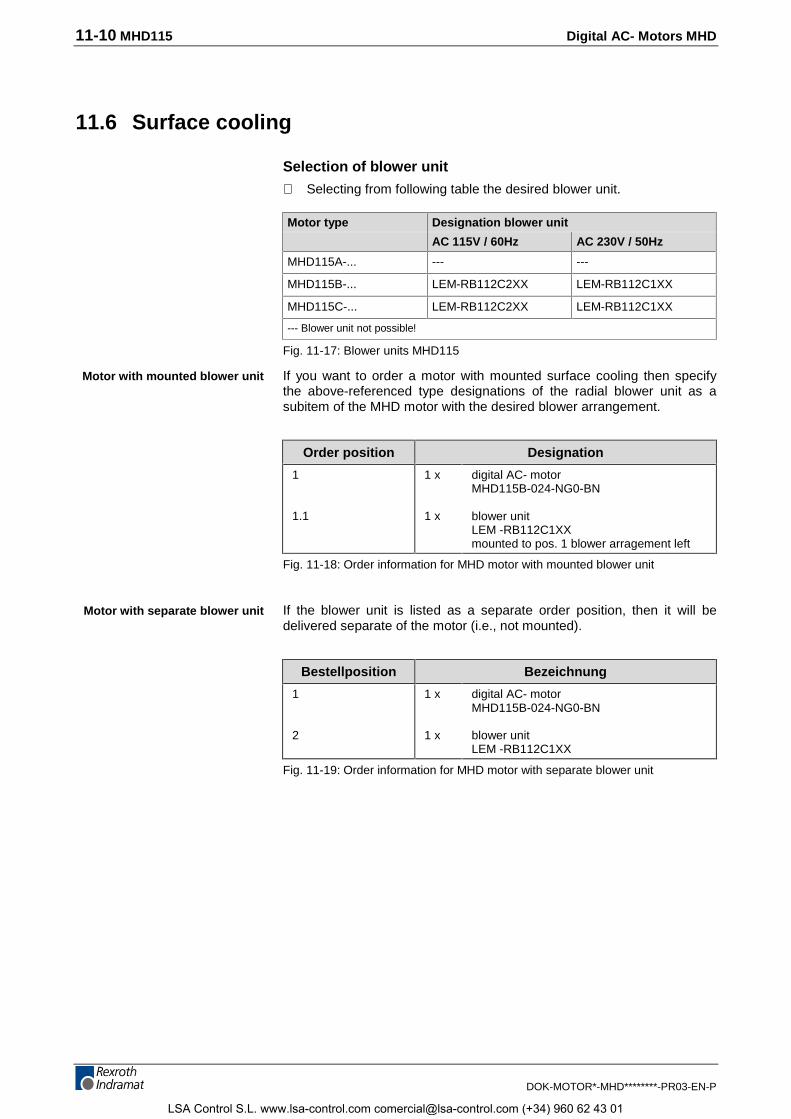
11-10 MHD115 Digital AC- Motors MHD
DOK-MOTOR*-MHD********-PR03-EN-P
11.6 Surface cooling
Selection of blower unit
⇒ Selecting from following table the desired blower unit.
Motor type Designation blower unit
AC 115V / 60Hz AC 230V / 50Hz
MHD115A-... --- ---
MHD115B-... LEM-RB112C2XX LEM-RB112C1XX
MHD115C-... LEM-RB112C2XX LEM-RB112C1XX
--- Blower unit not possible!
Fig. 11-17: Blower units MHD115
If you want to order a motor with mounted surface cooling then specifythe above-referenced type designations of the radial blower unit as asubitem of the MHD motor with the desired blower arrangement.
Order position Designation
1
1.1
1 x
1 x
digital AC- motorMHD115B-024-NG0-BN
blower unitLEM -RB112C1XXmounted to pos. 1 blower arragement left
Fig. 11-18: Order information for MHD motor with mounted blower unit
If the blower unit is listed as a separate order position, then it will bedelivered separate of the motor (i.e., not mounted).
Bestellposition Bezeichnung
1
2
1 x
1 x
digital AC- motorMHD115B-024-NG0-BN
blower unitLEM -RB112C1XX
Fig. 11-19: Order information for MHD motor with separate blower unit
Motor with mounted blower unit
Motor with separate blower unit
LSA Control S.L. www.lsa-control.com [email protected] (+34) 960 62 43 01
Digital AC- Motors MHD State at Delivery 12-1
DOK-MOTOR*-MHD********-PR03-EN-P
12 State at Delivery
12.1 General Information
The motors and their accessories such as cables are packaged incartons. Depending on the number or size of the cartons, these aremounted to pallets and fastened with taut metal bands. Cartons are alsopulled over the pallets to protect against adverse weather and thees arealso kept in place by bands.
12.2 Releasing the Taut Bands
CAUTION
There are uncontrolled motions of the taut bandswhen released!
Mechanical injuries are possible.⇒ Carefully release the bands!⇒ Maintain sufficient distance!
12.3 Documentation
The entire delivery is accompanied by only one envelope containing thedelivery documentation. It lists the merchandise by name and orderdesignation. If the listed contents are divided over several cartons(transport containers), then such is noted on the delivery slip or freightpapers.
The packaging lists the follownig information:
• type designation of motor
• customer
• delivery slip number
• consignment
• freight company
(See also Section 13 Identifying the Merchandise )
LSA Control S.L. www.lsa-control.com [email protected] (+34) 960 62 43 01
12-2 State at Delivery Digital AC- Motors MHD
DOK-MOTOR*-MHD********-PR03-EN-P
LSA Control S.L. www.lsa-control.com [email protected] (+34) 960 62 43 01
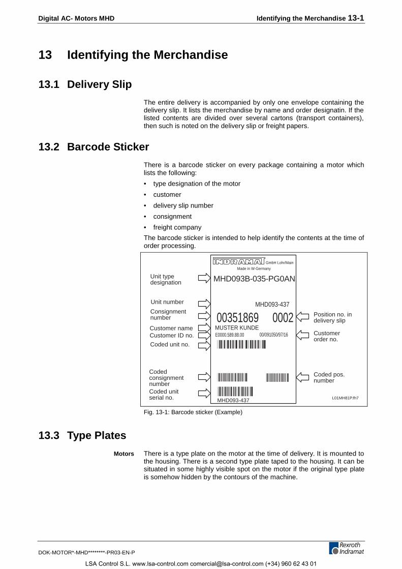
Digital AC- Motors MHD Identifying the Merchandise 13-1
DOK-MOTOR*-MHD********-PR03-EN-P
13 Identifying the Merchandise
13.1 Delivery Slip
The entire delivery is accompanied by only one envelope containing thedelivery slip. It lists the merchandise by name and order designatin. If thelisted contents are divided over several cartons (transport containers),then such is noted on the delivery slip or freight papers.
13.2 Barcode Sticker
There is a barcode sticker on every package containing a motor whichlists the following:
• type designation of the motor
• customer
• delivery slip number
• consignment
• freight company
The barcode sticker is intended to help identify the contents at the time oforder processing.
L01MH81P.fh7
00351869 0002
MHD093B-035-PG0AN
MHD093-437
00/091050/97/16E0000.589.88.00MUSTER KUNDE
Made in W-Germany
GmbH Lohr/Main
Position no. indelivery slip
Customerorder no.
Coded pos.number
Unit typedesignation
Unit number
Consignmentnumber
Customer nameCustomer ID no.
Coded unit no.
CodedconsignmentnumberCoded unitserial no. MHD093-437
Fig. 13-1: Barcode sticker (Example)
13.3 Type Plates
There is a type plate on the motor at the time of delivery. It is mounted tothe housing. There is a second type plate taped to the housing. It can besituated in some highly visible spot on the motor if the original type plateis somehow hidden by the contours of the machine.
Motors
LSA Control S.L. www.lsa-control.com [email protected] (+34) 960 62 43 01
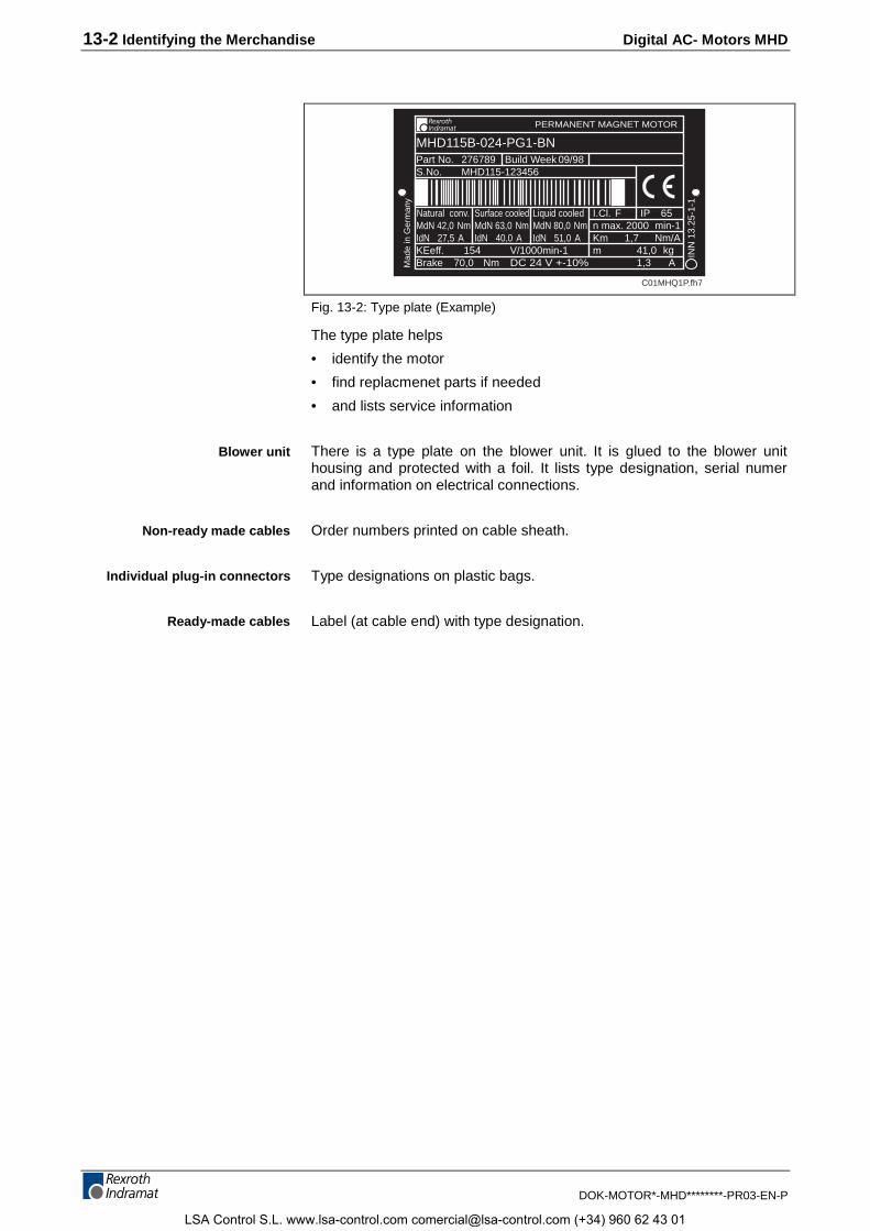
13-2 Identifying the Merchandise Digital AC- Motors MHD
DOK-MOTOR*-MHD********-PR03-EN-P
Part No.S.No.
Build Week
Mad
e in
Ger
man
y
I.Cl.n max.
KEeff.
PERMANENT MAGNET MOTOR
INN
13.
25-1
-1
MdN 42,0 Nm min-1Km
kgmBrake DC 24 V +-10%
276789 09/98MHD115-123456
MHD115B-024-PG1-BN
154
F 20001,7
41,0Nm/A
IP 65
Nm70,0V/1000min-1
A1,3
Natural conv.
IdN 27,5 AMdN 63,0 NmSurface cooled
IdN 40,0 A
Liquid cooled
C01MHQ1P.fh7
MdN 80,0 NmIdN 51,0 A
Fig. 13-2: Type plate (Example)
The type plate helps
• identify the motor
• find replacmenet parts if needed
• and lists service information
There is a type plate on the blower unit. It is glued to the blower unithousing and protected with a foil. It lists type designation, serial numerand information on electrical connections.
Order numbers printed on cable sheath.
Type designations on plastic bags.
Label (at cable end) with type designation.
Blower unit
Non-ready made cables
Individual plug-in connectors
Ready-made cables
LSA Control S.L. www.lsa-control.com [email protected] (+34) 960 62 43 01
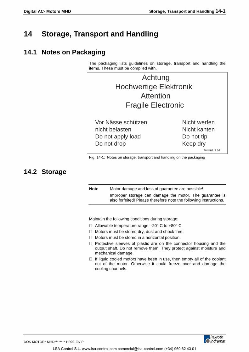
Digital AC- Motors MHD Storage, Transport and Handling 14-1
DOK-MOTOR*-MHD********-PR03-EN-P
14 Storage, Transport and Handling
14.1 Notes on Packaging
The packaging lists guidelines on storage, transport and handling theitems. These must be complied with.
AchtungHochwertige Elektronik
AttentionFragile Electronic
Vor Nässe schützen Nicht werfennicht belasten Nicht kantenDo not apply load Do not tipDo not drop Keep dry
Z01MH81P.fh7
Fig. 14-1: Notes on storage, transport and handling on the packaging
14.2 Storage
Note Motor damage and loss of guarantee are possible!
Improper storage can damage the motor. The guarantee isalso forfeited! Please therefore note the following instructions.
Maintain the following conditions during storage:
⇒ Allowable temperature range: -20° C to +80° C.⇒ Motors must be stored dry, dust and shock free.⇒ Motors must be stored in a horizontal position.⇒ Protective sleeves of plastic are on the connector housing and the
output shaft. Do not remove them. They protect against moisture andmechanical damage.
⇒ If liquid cooled motors have been in use, then empty all of the coolantout of the motor. Otherwise it could freeze over and damage thecooling channels.
LSA Control S.L. www.lsa-control.com [email protected] (+34) 960 62 43 01
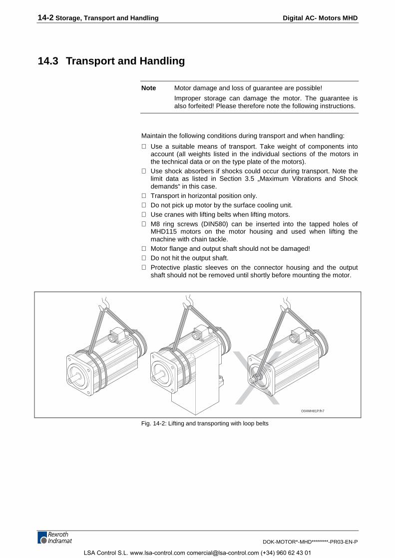
14-2 Storage, Transport and Handling Digital AC- Motors MHD
DOK-MOTOR*-MHD********-PR03-EN-P
14.3 Transport and Handling
Note Motor damage and loss of guarantee are possible!
Improper storage can damage the motor. The guarantee isalso forfeited! Please therefore note the following instructions.
Maintain the following conditions during transport and when handling:
⇒ Use a suitable means of transport. Take weight of components intoaccount (all weights listed in the individual sections of the motors inthe technical data or on the type plate of the motors).
⇒ Use shock absorbers if shocks could occur during transport. Note thelimit data as listed in Section 3.5 „Maximum Vibrations and Shockdemands“ in this case.
⇒ Transport in horizontal position only.⇒ Do not pick up motor by the surface cooling unit.⇒ Use cranes with lifting belts when lifting motors.⇒ M8 ring screws (DIN580) can be inserted into the tapped holes of
MHD115 motors on the motor housing and used when lifting themachine with chain tackle.
⇒ Motor flange and output shaft should not be damaged!⇒ Do not hit the output shaft.⇒ Protective plastic sleeves on the connector housing and the output
shaft should not be removed until shortly before mounting the motor.
O04MH81P.fh7
Fig. 14-2: Lifting and transporting with loop belts
LSA Control S.L. www.lsa-control.com [email protected] (+34) 960 62 43 01
Digital AC- Motors MHD Mounting and Installation 15-1
DOK-MOTOR*-MHD********-PR03-EN-P
15 Mounting and Installation
15.1 General Information on Mounting
⇒ Note all the warnings and safety instructions listed in section 2 SafetyInstructions for Electrical Drives. This will minimize the risk ofaccidents and avoid damage to installation and motor.
⇒ Conduct each step carefully. This ensures a trouble-free mountingand removal of the components.
15.2 Mounting the Motor
⇒ Have handy all tools, instructions, measuring and testing devices.⇒ Check components for cleanliness.⇒ Check whether the components are visibly damaged. Do not mount
damaged parts.⇒ Make sure that the mounting procedure takes place in a dry, dust free
environment.⇒ Make sure that the motor flange is burr free.⇒ Mount the motor. Maintain all the dimensions and tolerances of the
installation. Relevant data is listed in section "MHD ...", "DimensonalData".
⇒ If it is a liquid cooled motor, then establish the connections and checktheir density by pressing them with 5 bar. Also make sure that theflowthrough amount is correct.
15.3 Connecting the Motor
Once the motor is mechanically integrated, it can be connected.
DANGER
Danger to life due to electrical voltage!Handling the voltage-conducting sections can be
dangerous to life. Therefore:⇒ Work on the electrical aspects of the installation may
only be conducted by trained personnel. Appropriatetools are absolutely necessary.
⇒ Prior to working, shut power to installation off andsecure mains switch against unintentional oraccidental switching back on.
⇒ Prior to starting work, check whether there is anyresidual voltage in the installation (e.g., due tocapacitors and such). Wait until these havedischarged.
LSA Control S.L. www.lsa-control.com [email protected] (+34) 960 62 43 01
15-2 Mounting and Installation Digital AC- Motors MHD
DOK-MOTOR*-MHD********-PR03-EN-P
WARNING
Personnel injury or property damage possible!Interrupting or linking voltage-conductive lines can lead
to dangerous situation or property damage.Therefore:
⇒ Insert or remove connectors only if these are dry andnot conducting power.
⇒ All connectors must be firmly screwed into place whilethe installation is in operation.
WARNING
Danger of short circuit due to coolant or lubricants!A short circuit in a voltage-conductive line can lead to
unforeseeably dangerous situation or propertydamage. Therefore:
⇒ Place protective caps over the open end of powerconnectors during installation or when replacing drivecomponents, particularly if coolant or lubricant couldsomehow be sprayed on them.
The terminal diagrams from INDRAMAT exclusively help laying out theinstallation’ s circuit diagrams!
⇒ Connect motor as specified in the installation circuit diagrams of themachine manufactured! The terminal diagram in section 4.1 can beused as a help.
LSA Control S.L. www.lsa-control.com [email protected] (+34) 960 62 43 01
Digital AC- Motors MHD Mounting and Installation 15-3
DOK-MOTOR*-MHD********-PR03-EN-P
Connecting Ready-Made Cables
Power CablesFollow the instructions below when connecting the power connectorINS0681 with thread.
⇒ Place power connector at the thread of the connection housing in thecorrect position.
⇒ Manually tighten the screwed cap of the power connector. By slowingpulling the cable through it is possible to bring the power connectorinto its final position.
⇒ Tighten the screwed cap „manually and firmly“.
Follow the instructions below when connecting power connectorsINS0381 or INS0481 with quick-release bayonette joint:
⇒ Set the power connector to the bayonette joint of the connectorhousing in its correct position.
⇒ Turn the screwed cap of the power connector by hand until it clicksinto its end position (identified by red point and red triangular that arenow opposite each other).
Feedback CableFollow the instructions below when mounting the feedback connector:
⇒ Set the feedback connector to the thread of the connector housing inits correct position.
⇒ Manually tighten the screwed cap of the feedback connector. Bypulling through the cable it is possible to gradually bring the feedbackconnector into its end position.
⇒ Fix the screwed cap "manually and firmly" into place.
Connecting power connector forMHD041MHD071
and MHD090
Connecting power connectorMHD093MHD112
and MHD115
Connecting the feedbackconnector
LSA Control S.L. www.lsa-control.com [email protected] (+34) 960 62 43 01
15-4 Mounting and Installation Digital AC- Motors MHD
DOK-MOTOR*-MHD********-PR03-EN-P
Changing the Output Direction of Power andFeedback Connectors
Power connectorThe output direction of the power connectors of MHD041, MHD071 andMHD090 motors can be selected at the time of mounting. The flangedsocket can be turned (angle of turn is 270°).
How to set the cable direction wanted is described below.
Note: Do not use any tools, e.g., pliers or screwdrivers, for turningthe flanged socket of the motor. This could damage thesocket.
The flange of the motor is easy to turn if the correct plug is mounted. Thelever effect of the plug means that the flanged socket can be turned tothe desired direction by hand.
How to proceed:
⇒ Connect the motor power cable to the flanged socket.⇒ By turning the connected plug the socket can be moved into the
desired output direction.
The desired output direction is thus set.
Note: Each turn of the flanged socket decreases the holding torquein the set position. To ensure the needed holding torque of theflanged socket, the cable output direction should be changeda maximum of five times!
A „change“ (removal or mounting of the flanged socket by 90°) in theflanged socket is not necessary. The following problems and risks canresult from such a "change".
• The 0 ring seal between socket and motor housing can no longer beguaranteed.
• The required tightening torques may no longer be maintained.
• The TFL coating (screw locking device) of the mounting screws isworn down with each turn and becomes uneffective as a result.
Note: Forfeiture of guarantee!
If the cable direction is „changed“, then the guarantee isforfeited for the entire drive system. Change the cable outputdirection only by turning the flaned socket.
If the cable output direction of the power connectors was not taken intoconsideration at the time either MHD093, MHD112 or MHD115 wereordered, and it does not agree with the desired direction, then the cablecan be turned by 90°.
Proceed as follows in this case:
⇒ Release the two mounting screws 4 and remove the lid of theconnector box 2.
Changing connector outputdirections on MHD041
MHD071MHD090
Changing the cable outputdirection on MHD093
MHD112MHD115
LSA Control S.L. www.lsa-control.com [email protected] (+34) 960 62 43 01
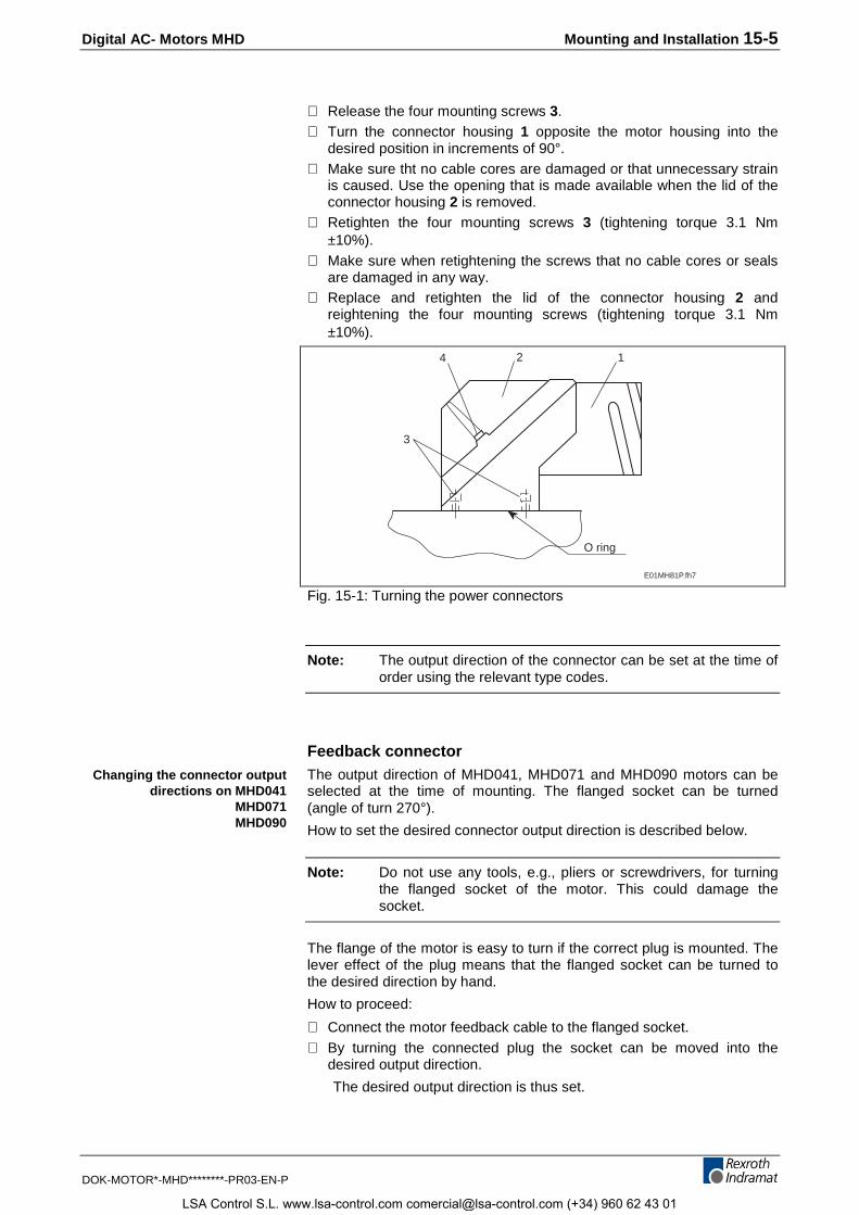
Digital AC- Motors MHD Mounting and Installation 15-5
DOK-MOTOR*-MHD********-PR03-EN-P
⇒ Release the four mounting screws 3.⇒ Turn the connector housing 1 opposite the motor housing into the
desired position in increments of 90°.⇒ Make sure tht no cable cores are damaged or that unnecessary strain
is caused. Use the opening that is made available when the lid of theconnector housing 2 is removed.
⇒ Retighten the four mounting screws 3 (tightening torque 3.1 Nm±10%).
⇒ Make sure when retightening the screws that no cable cores or sealsare damaged in any way.
⇒ Replace and retighten the lid of the connector housing 2 andreightening the four mounting screws (tightening torque 3.1 Nm±10%).
O ring
3
4 2 1
E01MH81P.fh7
Fig. 15-1: Turning the power connectors
Note: The output direction of the connector can be set at the time oforder using the relevant type codes.
Feedback connectorThe output direction of MHD041, MHD071 and MHD090 motors can beselected at the time of mounting. The flanged socket can be turned(angle of turn 270°).
How to set the desired connector output direction is described below.
Note: Do not use any tools, e.g., pliers or screwdrivers, for turningthe flanged socket of the motor. This could damage thesocket.
The flange of the motor is easy to turn if the correct plug is mounted. Thelever effect of the plug means that the flanged socket can be turned tothe desired direction by hand.
How to proceed:
⇒ Connect the motor feedback cable to the flanged socket.⇒ By turning the connected plug the socket can be moved into the
desired output direction.
The desired output direction is thus set.
Changing the connector outputdirections on MHD041
MHD071MHD090
LSA Control S.L. www.lsa-control.com [email protected] (+34) 960 62 43 01
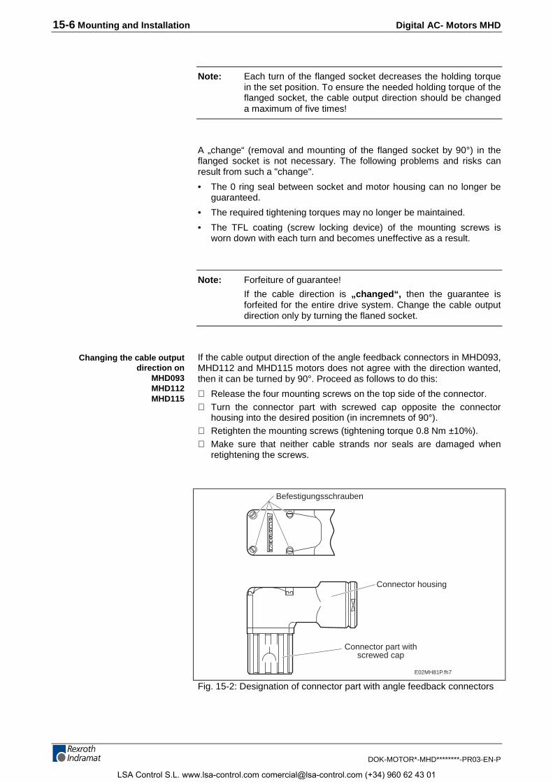
15-6 Mounting and Installation Digital AC- Motors MHD
DOK-MOTOR*-MHD********-PR03-EN-P
Note: Each turn of the flanged socket decreases the holding torquein the set position. To ensure the needed holding torque of theflanged socket, the cable output direction should be changeda maximum of five times!
A „change“ (removal and mounting of the flanged socket by 90°) in theflanged socket is not necessary. The following problems and risks canresult from such a "change".
• The 0 ring seal between socket and motor housing can no longer beguaranteed.
• The required tightening torques may no longer be maintained.
• The TFL coating (screw locking device) of the mounting screws isworn down with each turn and becomes uneffective as a result.
Note: Forfeiture of guarantee!
If the cable direction is „changed“, then the guarantee isforfeited for the entire drive system. Change the cable outputdirection only by turning the flaned socket.
If the cable output direction of the angle feedback connectors in MHD093,MHD112 and MHD115 motors does not agree with the direction wanted,then it can be turned by 90°. Proceed as follows to do this:
⇒ Release the four mounting screws on the top side of the connector.⇒ Turn the connector part with screwed cap opposite the connector
housing into the desired position (in incremnets of 90°).⇒ Retighten the mounting screws (tightening torque 0.8 Nm ±10%).⇒ Make sure that neither cable strands nor seals are damaged when
retightening the screws.
E02MH81P.fh7
Befestigungsschrauben
Connector housing
Connector part withscrewed cap
Fig. 15-2: Designation of connector part with angle feedback connectors
Changing the cable outputdirection on
MHD093MHD112MHD115
LSA Control S.L. www.lsa-control.com [email protected] (+34) 960 62 43 01
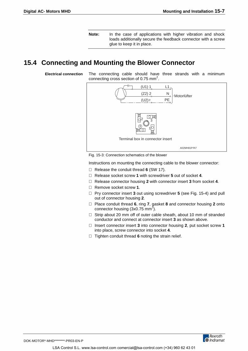
Digital AC- Motors MHD Mounting and Installation 15-7
DOK-MOTOR*-MHD********-PR03-EN-P
Note: In the case of applications with higher vibration and shockloads additionally secure the feedback connector with a screwglue to keep it in place.
15.4 Connecting and Mounting the Blower Connector
The connecting cable should have three strands with a minimumconnecting cross section of 0.75 mm2.
1
2 3
Terminal box in connector insert
(Z2) 2
(U1) 1
(U2)
N
L1
PEMotorlüfter
A02MH81P.fh7
Fig. 15-3: Connection schematics of the blower
Instructions on mounting the connecting cable to the blower connector:
⇒ Release the conduit thread 6 (SW 17).⇒ Release socket screw 1 with screwdriver 5 out of socket 4.⇒ Release connector housing 2 with connector insert 3 from socket 4.⇒ Remove socket screw 1.⇒ Pry connector insert 3 out using screwdriver 5 (see Fig. 15-4) and pull
out of connector housing 2.⇒ Place conduit thread 6, ring 7, gasket 8 and connector housing 2 onto
connector housing (3x0.75 mm2).⇒ Strip about 20 mm off of outer cable sheath, about 10 mm of stranded
conductor and connect at connector insert 3 as shown above.⇒ Insert connector insert 3 into connector housing 2, put socket screw 1
into place, screw connector into socket 4.⇒ Tighten conduit thread 6 noting the strain relief.
Electrical connection
LSA Control S.L. www.lsa-control.com [email protected] (+34) 960 62 43 01
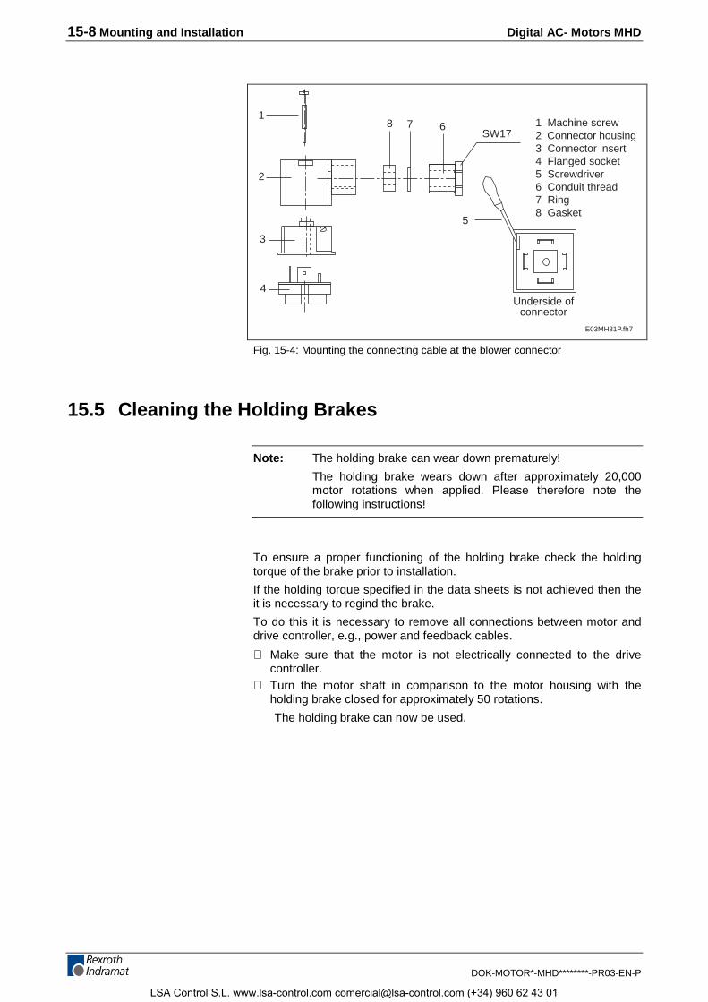
15-8 Mounting and Installation Digital AC- Motors MHD
DOK-MOTOR*-MHD********-PR03-EN-P
1
2
3
4
678SW17
Underside ofconnector
1 Machine screw2 Connector housing3 Connector insert4 Flanged socket5 Screwdriver6 Conduit thread7 Ring8 Gasket
E03MH81P.fh7
5
Fig. 15-4: Mounting the connecting cable at the blower connector
15.5 Cleaning the Holding Brakes
Note: The holding brake can wear down prematurely!
The holding brake wears down after approximately 20,000motor rotations when applied. Please therefore note thefollowing instructions!
To ensure a proper functioning of the holding brake check the holdingtorque of the brake prior to installation.
If the holding torque specified in the data sheets is not achieved then theit is necessary to regind the brake.
To do this it is necessary to remove all connections between motor anddrive controller, e.g., power and feedback cables.
⇒ Make sure that the motor is not electrically connected to the drivecontroller.
⇒ Turn the motor shaft in comparison to the motor housing with theholding brake closed for approximately 50 rotations.
The holding brake can now be used.
LSA Control S.L. www.lsa-control.com [email protected] (+34) 960 62 43 01
Digital AC- Motors MHD Service Guidelines 16-1
DOK-MOTOR*-MHD********-PR03-EN-P
16 Service Guidelines
16.1 Maintenance
The following should be performed regularly after the first year:
• The motors should be cleaned of dust, chips or similar.
• Control motor blower of the surface cooling unit.
• Check air circulation of cooling units.
• Check liquid cooling units for pressure, coolant levels, flow and so on.
16.2 Contacting Customer Service
To rapidly and efectively eliminate problems that may occur use ourService Hotline.
⇒ Prior to telephoning, note the following:
• type designations of the relevant drive controllers and motors
• the problem
• the readings of fault and diagnostics displays, if present.
The Service-Hotline can be reached:
Monday - Friday 7 - 23 CET
Saturday 8 - 20 CET
Sundays and holidays 9 - 19 CET
at
0171 - 333 882 6 or 0172 - 660 040 6.
⇒ If motors are returned to us, then please make a copy of the followingFault Report, fill it out completely and include it with the motor.
⇒ If the motors are liquid cooled, then remove all coolant prior totransport. There otherwise exsits the danger of the coolant freezingover and damaging the lines.
⇒ Add a copy of the fault report to the machine documents so that theuser of the machine can have access to it in the event repairs shouldbecome necessary.
This will ensure a rapid repair and help to quickly locate any application-dependent problems.
16.3 Fault Report
See next page.
LSA Control S.L. www.lsa-control.com [email protected] (+34) 960 62 43 01
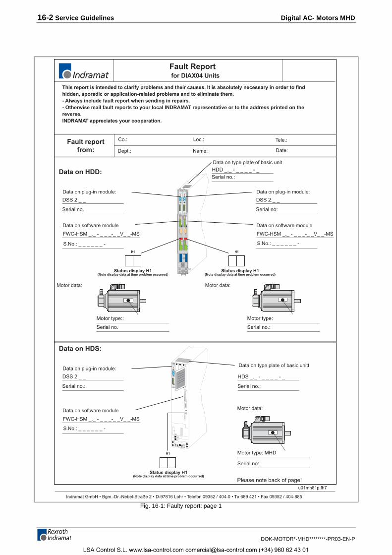
16-2 Service Guidelines Digital AC- Motors MHD
DOK-MOTOR*-MHD********-PR03-EN-P
Status display H1(Note display data at time problem occurred)
Status display H1(Note display data at time problem occurred)
Status display H1(Note display data at time problem occurred)
H3 ERR
E1
E2
E3
E4
E5
E6
+U
OV
X12
01
2 3
45
6
78
90
1
2 3
45
6
78
9D
SS2.
1
MS3
LOW
S2H
IGH
X11
RX
Fault Reportfor DIAX04 Units
Indramat GmbH � Bgm.-Dr.-Nebel-Straße 2 � D-97816 Lohr � Telefon 09352 / 404-0 � Tx 689 421 � Fax 09352 / 404-885
Data on HDD:
FWC-HSM _._ - _ _ _-_ _V_ _-MS
S.No.: _ _ _ _ _ _ -
Data on software module
Data on plug-in module:
DSS 2._ _
Serial no.
Fault reportfrom:
Co.:
Date:
Loc.:
Dept.:
Tele.:
Name:
H1
HDD _._ - _ _ _ _ - _Serial no.:
Data on type plate of basic unit
FWC-HSM _._ - _ _ _-_ _V_ _-MS
S.No.: _ _ _ _ _ _ -
Data on software module
Data on plug-in module:
DSS 2._ _
Serial no:
H1
Serial no.:
Motor type:
Motor data:
Serial no.
Motor type::
Motor data:
H3 ERR
E1
E2
E3
E4
E5
E6
+U
OV
X12
01
2 3
45
6
78
90
1
2 3
45
6
78
9D
SS2.
1
MS3
LOW
S2H
IGH
X11
RX
H3 ERR
E1
E2
E3
E4
E5
E6
+U
OV
X12
01
2 3
45
6
78
90
1
2 3
45
6
78
9D
SS2.
1
MS3
LOW
S2H
IGH
X11
RX
Data on HDS:
HDS _._ - _ _ _ _ - _
Serial no.:
Serial no:
Motor type: MHD
FWC-HSM _._ - _ _ _-_ _V_ _-MS
S.No.: _ _ _ _ _ _ -
Data on software module Motor data:
Data on type plate of basic unittData on plug-in module:
DSS 2._ _
Serial no.:
H1
Please note back of page!
This report is intended to clarify problems and their causes. It is absolutely necessary in order to findhidden, sporadic or application-related problems and to eliminate them.- Always include fault report when sending in repairs.- Otherwise mail fault reports to your local INDRAMAT representative or to the address printed on thereverse.INDRAMAT appreciates your cooperation.
u01mh81p.fh7
Fig. 16-1: Faulty report: page 1
LSA Control S.L. www.lsa-control.com [email protected] (+34) 960 62 43 01
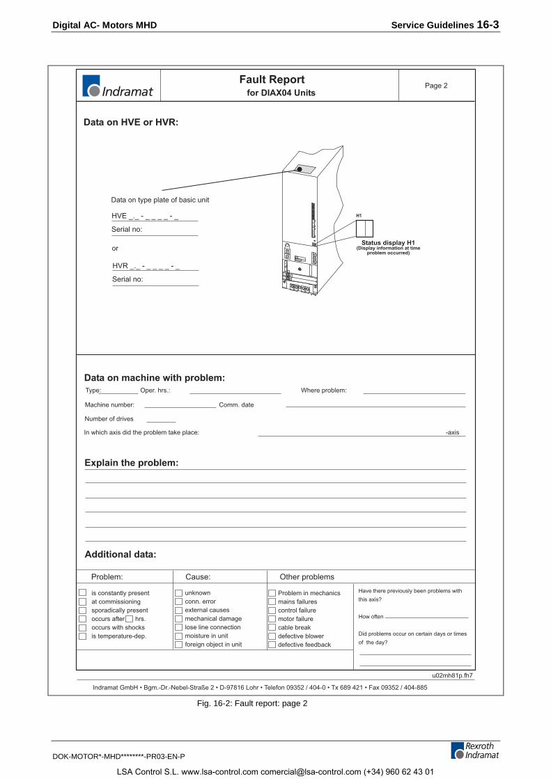
Digital AC- Motors MHD Service Guidelines 16-3
DOK-MOTOR*-MHD********-PR03-EN-P
Status display H1(Display information at time
problem occurred)
Fault Reportfor DIAX04 Units
Indramat GmbH � Bgm.-Dr.-Nebel-Straße 2 � D-97816 Lohr � Telefon 09352 / 404-0 � Tx 689 421 � Fax 09352 / 404-885
Problem: Cause: Other problems
is constantly presentat commissioningsporadically presentoccurs after hrs.occurs with shocksis temperature-dep.
unknownconn. errorexternal causesmechanical damagelose line connectionmoisture in unitforeign object in unit
Problem in mechanicsmains failurescontrol failuremotor failurecable breakdefective blowerdefective feedback
Have there previously been problems with
this axis?
How often
Did problems occur on certain days or times
of the day?
Additional data:
Data on machine with problem:
Explain the problem:
Machine number:
Type: Where problem:
Comm. date
Data on HVE or HVR:
Oper. hrs.:
Number of drives
HVE _._ - _ _ _ _ - _
Serial no:
Data on type plate of basic unit
HVR _._ - _ _ _ _ - _
Serial no:
or
H1
X1
Type
Barcode
L-
L+
In which axis did the problem take place: -axis
Page 2
u02mh81p.fh7
Fig. 16-2: Fault report: page 2
LSA Control S.L. www.lsa-control.com [email protected] (+34) 960 62 43 01

16-4 Service Guidelines Digital AC- Motors MHD
DOK-MOTOR*-MHD********-PR03-EN-P
LSA Control S.L. www.lsa-control.com [email protected] (+34) 960 62 43 01
Digital AC- Motors MHD Index 17-1
DOK-MOTOR*-MHD********-PR03-EN-P
17 Index
AAmbient Temperature 3-1Ambient temperature and installation elevation 3-1Application range 1-1
BBarcode sticker 13-1Bearing service life 3-9
CCable cross sections 4-15, 4-16, 4-17Commutation 1-1, 1-3Components 1-3Construction 1-3Coolant 5-1Coolant lines 5-1Cooling method 1-3Cooling system components 5-1
DDesigns 1-3Digital servo feedback (HSF) 1-4Digital servo feedback(HSF) with integral multiturn absolute encoder 1-4Dynamics 1-1
EElectrical connection
feedback cables 4-12Feedback connectors 4-18Parts 4-14power cable 4-2
Electrical connectionsangle feedback connectors 3-14plans for MHD motors 4-1
Ffeedback cables 4-12Feedback connector 15-3Feedback connectors 4-18Feedback data memory 1-4
HHolding brake 1-3, 3-11Housing Finish 3-6
IInstallation circuit diagrams 15-2Installation Elevation 3-1
KKnee speed 3-15
LLiquid cooling 3-11
LSA Control S.L. www.lsa-control.com [email protected] (+34) 960 62 43 01
17-2 Index Digital AC- Motors MHD
DOK-MOTOR*-MHD********-PR03-EN-P
Load factor 3-1
MMaintenance-free operation 1-1Motor feedback 1-3, 1-4
Technical data 1-4Mounting drive elements 3-10
OOperating curves 3-15Operating reliability 1-1Output direction 3-13Output shaft 1-3
Output shaft with keyway 3-8Plain output shaft 3-7Shaft load 3-8Thermal changes in length 3-9
Overload capabilities 1-1
PPower cables 4-2Power connector 15-4Power data 1-1Power overview 1-2Pressure drop 5-2Prime Coat 3-6Protection against contact with hot parts 2-8Protection category 3-2
SSafety Instructions 2-1
Battery safety 2-9General 2-3Hazards by improper use 2-2Protection against contact with electrical parts and not grounded enclosures 2-4Protection against dangerous movements 2-6Protection against magnetic and electromagnetic fields during operations and mounting2-7Protection by protective low voltage (PELV) against electrical shock 2-5Protection during handling and installation 2-8
Safety Instructions for Electrical Drives 2-1Service-Hotline 16-1Shaft capacity
MHD041 6-4MHD071 7-4MHD091 8-4MHD093 9-7MHD112 10-9MHD115 11-6
Shaft loadAllowed axial force 3-9Allowed radial force 3-8Maximum allowed radial force 3-8
Shock demands 3-6Surface cooling 3-10
TType Codes
MHD041 6-6MHD071 7-6MHD090 8-6MHD093 9-10MHD112 10-12MHD115 11-9
Type of position detection
LSA Control S.L. www.lsa-control.com [email protected] (+34) 960 62 43 01
Digital AC- Motors MHD Index 17-3
DOK-MOTOR*-MHD********-PR03-EN-P
absolute 1-4relative 1-4
Type plate 13-2
Vvia specific bearings 3-10Vibration demands 3-6
LSA Control S.L. www.lsa-control.com [email protected] (+34) 960 62 43 01
17-4 Index Digital AC- Motors MHD
DOK-MOTOR*-MHD********-PR03-EN-P
LSA Control S.L. www.lsa-control.com [email protected] (+34) 960 62 43 01
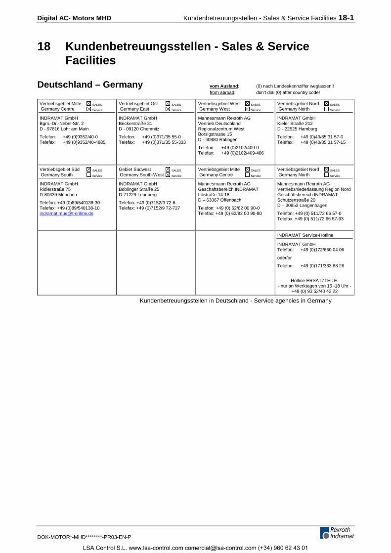
Digital AC- Motors MHD Kundenbetreuungsstellen - Sales & Service Facilities 18-1
DOK-MOTOR*-MHD********-PR03-EN-P
18 Kundenbetreuungsstellen - Sales & ServiceFacilities
Deutschland – Germany vom Ausland: (0) nach Landeskennziffer weglassen!!from abroad: don’t dial (0) after country code!
Vertriebsgebiet Mitte SALES
Germany Centre Service
INDRAMAT GmbHBgm.-Dr.-Nebel-Str. 2D - 97816 Lohr am Main
Telefon: +49 (0)9352/40-0Telefax: +49 (0)9352/40-4885
Vertriebsgebiet Ost SALES
Germany East Service
INDRAMAT GmbHBeckerstraße 31D - 09120 Chemnitz
Telefon: +49 (0)371/35 55-0Telefax: +49 (0)371/35 55-333
Vertriebsgebiet West SALES
Germany West Service
Mannesmann Rexroth AGVertrieb DeutschlandRegionalzentrum WestBorsigstrasse 15D - 40880 Ratingen
Telefon: +49 (0)2102/409-0Telefax: +49 (0)2102/409-406
Vertriebsgebiet Nord SALES
Germany North Service
INDRAMAT GmbHKieler Straße 212D - 22525 Hamburg
Telefon: +49 (0)40/85 31 57-0Telefax: +49 (0)40/85 31 57-15
Vertriebsgebiet Süd SALES
Germany South Service
INDRAMAT GmbHRidlerstraße 75D-80339 München
Telefon: +49 (0)89/540138-30Telefax: +49 (0)89/[email protected]
Gebiet Südwest SALES
Germany South-West Service
INDRAMAT GmbHBöblinger Straße 25D-71229 Leonberg
Telefon: +49 (0)7152/9 72-6Telefax: +49 (0)7152/9 72-727
Vertriebsgebiet Mitte SALES
Germany Centre Service
Mannesmann Rexroth AGGeschäftsbereich INDRAMATLilistraße 14-18D – 63067 Offenbach
Telefon: +49 (0) 62/82 00 90-0Telefax: +49 (0) 62/82 00 90-80
Vertriebsgebiet Nord SALES
Germany North Service
Mannesmann Rexroth AGVertriebsniederlassung Region NordGeschäftsbereich INDRAMATSchützenstraße 20D – 30853 Langenhagen
Telefon: +49 (0) 511/72 66 57-0Telefax: +49 (0) 511/72 66 57-93
INDRAMAT Service-Hotline
INDRAMAT GmbHTelefon: +49 (0)172/660 04 06
oder/or
Telefon: +49 (0)171/333 88 26
Hotline ERSATZTEILE:- nur an Werktagen von 15 -18 Uhr -
+49 (0) 93 52/40 42 22
Kundenbetreuungsstellen in Deutschland - Service agencies in Germany
LSA Control S.L. www.lsa-control.com [email protected] (+34) 960 62 43 01
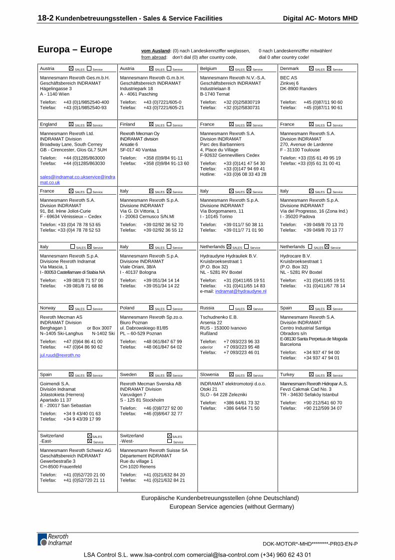
18-2 Kundenbetreuungsstellen - Sales & Service Facilities Digital AC- Motors MHD
DOK-MOTOR*-MHD********-PR03-EN-P
Europa – Europe vom Ausland: (0) nach Landeskennziffer weglassen, 0 nach Landeskennziffer mitwählen!from abroad: don’t dial (0) after country code, dial 0 after country code!
Austria SALES Service
Mannesmann Rexroth Ges.m.b.H.Geschäftsbereich INDRAMATHägelingasse 3A - 1140 Wien
Telefon: +43 (0)1/9852540-400Telefax: +43 (0)1/9852540-93
Austria SALES Service
Mannesmann Rexroth G.m.b.H.Geschäftsbereich INDRAMATIndustriepark 18A - 4061 Pasching
Telefon: +43 (0)7221/605-0Telefax: +43 (0)7221/605-21
Belgium SALES Service
Mannesmann Rexroth N.V.-S.A.Geschäftsbereich INDRAMATIndustrielaan 8B-1740 Ternat
Telefon: +32 (0)2/5830719Telefax: +32 (0)2/5830731
Denmark SALES Service
BEC ASZinkvej 6DK-8900 Randers
Telefon: +45 (0)87/11 90 60Telefax: +45 (0)87/11 90 61
England SALES Service
Mannesmann Rexroth Ltd.INDRAMAT DivisionBroadway Lane, South CerneyGB - Cirencester, Glos GL7 5UH
Telefon: +44 (0)1285/863000Telefax: +44 (0)1285/863030
[email protected]@indramat.co.uk
Finland SALES Service
Rexroth Mecman OyINDRAMAT divisionAnsatie 6SF-017 40 Vantaa
Telefon: +358 (0)9/84 91-11Telefax: +358 (0)9/84 91-13 60
France SALES Service
Mannesmann Rexroth S.A.Division INDRAMATParc des Barbanniers4, Place du VillageF-92632 Gennevilliers Cedex
Telefon: +33 (0)141 47 54 30Telefax: +33 (0)147 94 69 41Hotline: +33 (0)6 08 33 43 28
France SALES Service
Mannesmann Rexroth S.A.Division INDRAMAT270, Avenue de LardenneF - 31100 Toulouse
Telefon: +33 (0)5 61 49 95 19Telefax: +33 (0)5 61 31 00 41
France SALES Service
Mannesmann Rexroth S.A.Division INDRAMAT91, Bd. Irène Joliot-CurieF - 69634 Vénissieux – Cedex
Telefon: +33 (0)4 78 78 53 65Telefax: +33 (0)4 78 78 52 53
Italy SALES Service
Mannesmann Rexroth S.p.A.Divisione INDRAMATVia G. Di Vittoria, 1I - 20063 Cernusco S/N.MI
Telefon: +39 02/92 36 52 70Telefax: +39 02/92 36 55 12
Italy SALES Service
Mannesmann Rexroth S.p.A.Divisione INDRAMATVia Borgomanero, 11I - 10145 Torino
Telefon: +39 011/7 50 38 11Telefax: +39 011/7 71 01 90
Italy SALES Service
Mannesmann Rexroth S.p.A.Divisione INDRAMATVia del Progresso, 16 (Zona Ind.)I - 35020 Padova
Telefon: +39 049/8 70 13 70Telefax: +39 049/8 70 13 77
Italy SALES Service
Mannesmann Rexroth S.p.A.Divisione Rexroth IndramatVia Mascia, 1I - 80053 Castellamare di Stabia NA
Telefon: +39 081/8 71 57 00Telefax: +39 081/8 71 68 86
Italy SALES Service
Mannesmann Rexroth S.p.A.Divisione INDRAMATViale Oriani, 38/AI - 40137 Bologna
Telefon: +39 051/34 14 14Telefax: +39 051/34 14 22
Netherlands SALES Service
Hydraudyne Hydrauliek B.V.Kruisbroeksestraat 1(P.O. Box 32)NL - 5281 RV Boxtel
Telefon: +31 (0)411/65 19 51Telefax: +31 (0)411/65 14 83e-mail: [email protected]
Netherlands SALES Service
Hydrocare B.V.Kruisbroeksestraat 1(P.O. Box 32)NL - 5281 RV Boxtel
Telefon: +31 (0)411/65 19 51Telefax: +31 (0)411/67 78 14
Norway SALES Service
Rexroth Mecman ASINDRAMAT DivisionBerghagan 1 or Box 3007N–1405 Ski-Langhus N-1402 Ski
Telefon: +47 (0)64 86 41 00Telefax: +47 (0)64 86 90 62
Poland SALES Service
Mannesmann Rexroth Sp.zo.o.Biuro Poznanul. Dabrowskiego 81/85PL – 60-529 Poznan
Telefon: +48 061/847 67 99Telefax: +48 061/847 64 02
Russia SALES Service
Tschudnenko E.B.Arsenia 22RUS - 153000 IvanovoRußland
Telefon: +7 093/223 96 33oder/or +7 093/223 95 48Telefax: +7 093/223 46 01
Spain SALES Service
Mannesmann Rexroth S.A.Divisiòn INDRAMATCentro Industrial SantigaObradors s/nE-08130 Santa Perpetua de MogodaBarcelona
Telefon: +34 937 47 94 00Telefax: +34 937 47 94 01
Spain SALES Service
Goimendi S.A.División IndramatJolastokieta (Herrera)Apartado 11 37E - 20017 San Sebastian
Telefon: +34 9 43/40 01 63Telefax: +34 9 43/39 17 99
Sweden SALES Service
Rexroth Mecman Svenska ABINDRAMAT DivisionVaruvägen 7S - 125 81 Stockholm
Telefon: +46 (0)8/727 92 00Telefax: +46 (0)8/647 32 77
Slowenia SALES Service
INDRAMAT elektromotorji d.o.o.Otoki 21SLO - 64 228 Zelezniki
Telefon: +386 64/61 73 32Telefax: +386 64/64 71 50
Turkey SALES Service
Mannesmann Rexroth Hidropar A..S.Fevzi Cakmak Cad No. 3TR - 34630 Sefaköy Istanbul
Telefon: +90 212/541 60 70Telefax: +90 212/599 34 07
Switzerland SALES
-East- Service
Mannesmann Rexroth Schweiz AGGeschäftsbereich INDRAMATGewerbestraße 3CH-8500 Frauenfeld
Telefon: +41 (0)52/720 21 00Telefax: +41 (0)52/720 21 11
Switzerland SALES
-West- Service
Mannesmann Rexroth Suisse SADépartement INDRAMATRue du village 1CH-1020 Renens
Telefon: +41 (0)21/632 84 20Telefax: +41 (0)21/632 84 21
Europäische Kundenbetreuungsstellen (ohne Deutschland)European Service agencies (without Germany)
LSA Control S.L. www.lsa-control.com [email protected] (+34) 960 62 43 01
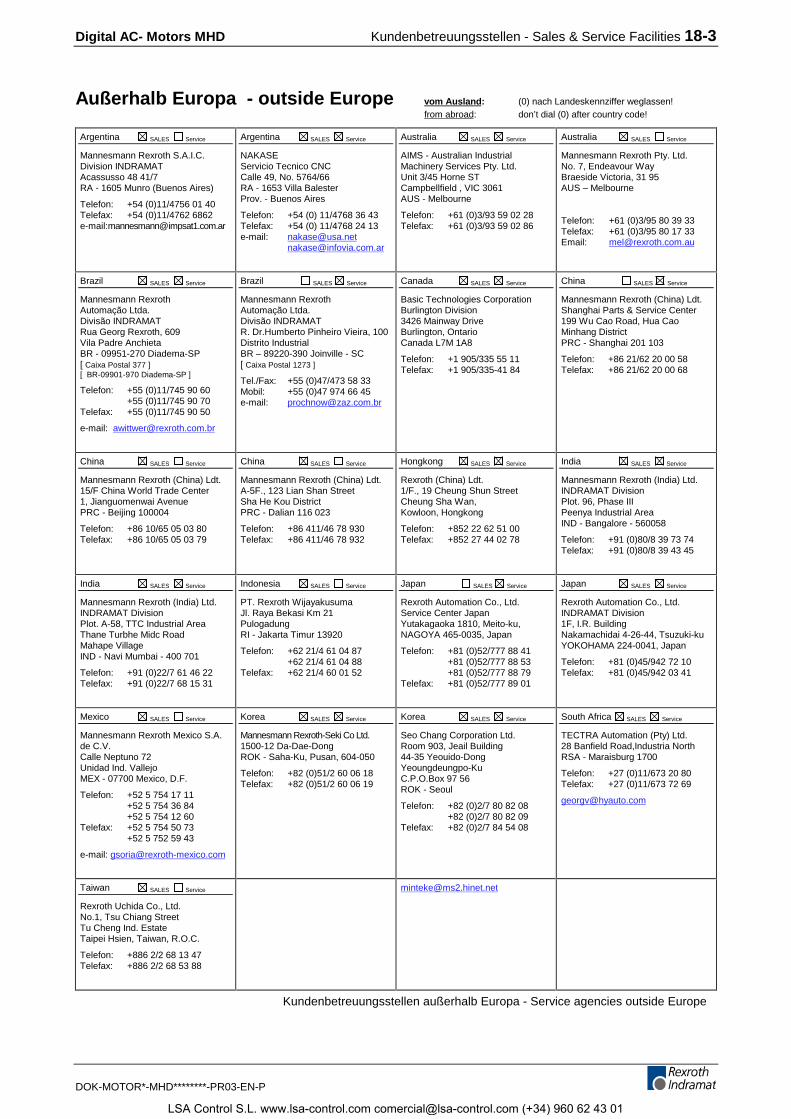
Digital AC- Motors MHD Kundenbetreuungsstellen - Sales & Service Facilities 18-3
DOK-MOTOR*-MHD********-PR03-EN-P
Außerhalb Europa - outside Europe vom Ausland: (0) nach Landeskennziffer weglassen!from abroad: don’t dial (0) after country code!
Argentina SALES Service
Mannesmann Rexroth S.A.I.C.Division INDRAMATAcassusso 48 41/7RA - 1605 Munro (Buenos Aires)
Telefon: +54 (0)11/4756 01 40Telefax: +54 (0)11/4762 6862e-mail:[email protected]
Argentina SALES Service
NAKASEServicio Tecnico CNCCalle 49, No. 5764/66RA - 1653 Villa BalesterProv. - Buenos Aires
Telefon: +54 (0) 11/4768 36 43Telefax: +54 (0) 11/4768 24 13e-mail: [email protected]
Australia SALES Service
AIMS - Australian IndustrialMachinery Services Pty. Ltd.Unit 3/45 Horne STCampbellfield , VIC 3061AUS - Melbourne
Telefon: +61 (0)3/93 59 02 28Telefax: +61 (0)3/93 59 02 86
Australia SALES Service
Mannesmann Rexroth Pty. Ltd.No. 7, Endeavour WayBraeside Victoria, 31 95AUS – Melbourne
Telefon: +61 (0)3/95 80 39 33Telefax: +61 (0)3/95 80 17 33Email: [email protected]
Brazil SALES Service
Mannesmann RexrothAutomação Ltda.Divisão INDRAMATRua Georg Rexroth, 609Vila Padre AnchietaBR - 09951-270 Diadema-SP[ Caixa Postal 377 ][ BR-09901-970 Diadema-SP ]
Telefon: +55 (0)11/745 90 60+55 (0)11/745 90 70
Telefax: +55 (0)11/745 90 50
e-mail: [email protected]
Brazil SALES Service
Mannesmann RexrothAutomação Ltda.Divisão INDRAMATR. Dr.Humberto Pinheiro Vieira, 100Distrito IndustrialBR – 89220-390 Joinville - SC[ Caixa Postal 1273 ]
Tel./Fax: +55 (0)47/473 58 33Mobil: +55 (0)47 974 66 45e-mail: [email protected]
Canada SALES Service
Basic Technologies CorporationBurlington Division3426 Mainway DriveBurlington, OntarioCanada L7M 1A8
Telefon: +1 905/335 55 11Telefax: +1 905/335-41 84
China SALES Service
Mannesmann Rexroth (China) Ldt.Shanghai Parts & Service Center199 Wu Cao Road, Hua CaoMinhang DistrictPRC - Shanghai 201 103
Telefon: +86 21/62 20 00 58Telefax: +86 21/62 20 00 68
China SALES Service
Mannesmann Rexroth (China) Ldt.15/F China World Trade Center1, Jianguomenwai AvenuePRC - Beijing 100004
Telefon: +86 10/65 05 03 80Telefax: +86 10/65 05 03 79
China SALES Service
Mannesmann Rexroth (China) Ldt.A-5F., 123 Lian Shan StreetSha He Kou DistrictPRC - Dalian 116 023
Telefon: +86 411/46 78 930Telefax: +86 411/46 78 932
Hongkong SALES Service
Rexroth (China) Ldt.1/F., 19 Cheung Shun StreetCheung Sha Wan,Kowloon, Hongkong
Telefon: +852 22 62 51 00Telefax: +852 27 44 02 78
India SALES Service
Mannesmann Rexroth (India) Ltd.INDRAMAT DivisionPlot. 96, Phase IIIPeenya Industrial AreaIND - Bangalore - 560058
Telefon: +91 (0)80/8 39 73 74Telefax: +91 (0)80/8 39 43 45
India SALES Service
Mannesmann Rexroth (India) Ltd.INDRAMAT DivisionPlot. A-58, TTC Industrial AreaThane Turbhe Midc RoadMahape VillageIND - Navi Mumbai - 400 701
Telefon: +91 (0)22/7 61 46 22Telefax: +91 (0)22/7 68 15 31
Indonesia SALES Service
PT. Rexroth WijayakusumaJl. Raya Bekasi Km 21PulogadungRI - Jakarta Timur 13920
Telefon: +62 21/4 61 04 87+62 21/4 61 04 88
Telefax: +62 21/4 60 01 52
Japan SALES Service
Rexroth Automation Co., Ltd.Service Center JapanYutakagaoka 1810, Meito-ku,NAGOYA 465-0035, Japan
Telefon: +81 (0)52/777 88 41+81 (0)52/777 88 53+81 (0)52/777 88 79
Telefax: +81 (0)52/777 89 01
Japan SALES Service
Rexroth Automation Co., Ltd.INDRAMAT Division1F, I.R. BuildingNakamachidai 4-26-44, Tsuzuki-kuYOKOHAMA 224-0041, Japan
Telefon: +81 (0)45/942 72 10Telefax: +81 (0)45/942 03 41
Mexico SALES Service
Mannesmann Rexroth Mexico S.A.de C.V.Calle Neptuno 72Unidad Ind. VallejoMEX - 07700 Mexico, D.F.
Telefon: +52 5 754 17 11+52 5 754 36 84+52 5 754 12 60
Telefax: +52 5 754 50 73+52 5 752 59 43
e-mail: [email protected]
Korea SALES Service
Mannesmann Rexroth-Seki Co Ltd.1500-12 Da-Dae-DongROK - Saha-Ku, Pusan, 604-050
Telefon: +82 (0)51/2 60 06 18Telefax: +82 (0)51/2 60 06 19
Korea SALES Service
Seo Chang Corporation Ltd.Room 903, Jeail Building44-35 Yeouido-DongYeoungdeungpo-KuC.P.O.Box 97 56ROK - Seoul
Telefon: +82 (0)2/7 80 82 08+82 (0)2/7 80 82 09
Telefax: +82 (0)2/7 84 54 08
South Africa SALES Service
TECTRA Automation (Pty) Ltd.28 Banfield Road,Industria NorthRSA - Maraisburg 1700
Telefon: +27 (0)11/673 20 80Telefax: +27 (0)11/673 72 69
Taiwan SALES Service
Rexroth Uchida Co., Ltd.No.1, Tsu Chiang StreetTu Cheng Ind. EstateTaipei Hsien, Taiwan, R.O.C.
Telefon: +886 2/2 68 13 47Telefax: +886 2/2 68 53 88
Kundenbetreuungsstellen außerhalb Europa - Service agencies outside Europe
LSA Control S.L. www.lsa-control.com [email protected] (+34) 960 62 43 01
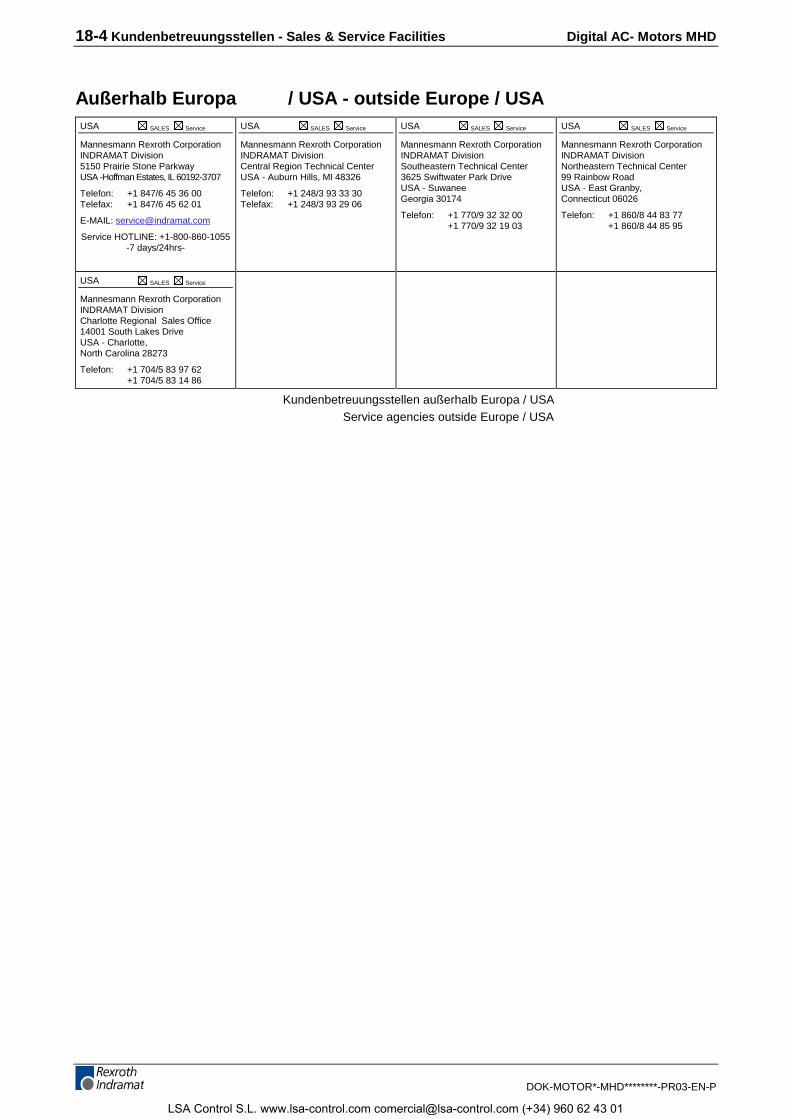
18-4 Kundenbetreuungsstellen - Sales & Service Facilities Digital AC- Motors MHD
DOK-MOTOR*-MHD********-PR03-EN-P
Außerhalb Europa / USA - outside Europe / USAUSA SALES Service
Mannesmann Rexroth CorporationINDRAMAT Division5150 Prairie Stone ParkwayUSA -Hoffman Estates, IL 60192-3707
Telefon: +1 847/6 45 36 00Telefax: +1 847/6 45 62 01
E-MAIL: [email protected]
Service HOTLINE: +1-800-860-1055-7 days/24hrs-
USA SALES Service
Mannesmann Rexroth CorporationINDRAMAT DivisionCentral Region Technical CenterUSA - Auburn Hills, MI 48326
Telefon: +1 248/3 93 33 30Telefax: +1 248/3 93 29 06
USA SALES Service
Mannesmann Rexroth CorporationINDRAMAT DivisionSoutheastern Technical Center3625 Swiftwater Park DriveUSA - SuwaneeGeorgia 30174
Telefon: +1 770/9 32 32 00+1 770/9 32 19 03
USA SALES Service
Mannesmann Rexroth CorporationINDRAMAT DivisionNortheastern Technical Center99 Rainbow RoadUSA - East Granby,Connecticut 06026
Telefon: +1 860/8 44 83 77+1 860/8 44 85 95
USA SALES Service
Mannesmann Rexroth CorporationINDRAMAT DivisionCharlotte Regional Sales Office14001 South Lakes DriveUSA - Charlotte,North Carolina 28273
Telefon: +1 704/5 83 97 62+1 704/5 83 14 86
Kundenbetreuungsstellen außerhalb Europa / USA Service agencies outside Europe / USA
LSA Control S.L. www.lsa-control.com [email protected] (+34) 960 62 43 01

LSA Control S.L. www.lsa-control.com [email protected] (+34) 960 62 43 01

273697
IndramatRexroth
Prin
ted
in G
erm
any
LSA Control S.L. www.lsa-control.com [email protected] (+34) 960 62 43 01