CATALOGO SERIE-AB Rev-03 mantenimiento EN - CMO Valves
11
KNIFE-GATE VALVES AB SERIES C.M.O. Amategui Aldea 142, 20400 Txarama‐Tolosa (SPAIN) MAN‐AB.EN03 Tel. Nacional: 902.40.80.50 Fax: 902.40.80.51 / Tel. Internacional: 34.943.67.33.99 Fax: 34.943.67.24.40 [email protected] http://www.cmo.es page 1 29/10/2013 INSTRUCTIONS AND MAINTENANCE MANUAL SERIES: AB
Transcript of CATALOGO SERIE-AB Rev-03 mantenimiento EN - CMO Valves
K N I F E - G A T E V A L V E S A B S E R I E S
C.M.O.
Amategui Aldea 142, 20400 Txarama‐Tolosa (SPAIN) MAN‐AB.EN03
Tel. Nacional: 902.40.80.50 Fax: 902.40.80.51 / Tel. Internacional: 34.943.67.33.99 Fax: [email protected] http://www.cmo.es page1
29/10/2013
INSTRUCTIONS AND MAINTENANCE
MANUAL
SERIES: AB
K N I F E - G A T E V A L V E S A B S E R I E S
C.M.O.
Amategui Aldea 142, 20400 Txarama‐Tolosa (SPAIN) MAN‐AB.EN03
Tel. Nacional: 902.40.80.50 Fax: 902.40.80.51 / Tel. Internacional: 34.943.67.33.99 Fax: [email protected] http://www.cmo.es page2
DESCRIPTION
Machinery Directive: DIR 2006/42/EC (MACHINERY)
Pressure Equipment Directive: DIR 97/23/EC (PED) ART.3, P.3
Potential Explosive Atmospheres Directive: DIR 94/9/CE (ATEX) CAT.3 ZONE 2 and 22 GD.
Valve AB complies with the Directive on Equipment and Protective Systems for Potentially Explosive
Atmospheres. In these cases the logo will appear on the identification label. This label shows the exact
classification of the zone in which the valve can be used. The user is responsible for its use in any other
zone.
HANDLING
When handling the equipment please pay special attention to the following points:
To prevent damage, especially to the anticorrosive protection, it is recommended to use soft straps to lift the CMO knife gate valves. These straps must be fitted to the top of valve, around its body.
Do not lift the valve or hold it by the actuator. Lifting the valve by the actuator can lead to operating problems as it is not designed to withstand the valve’s weight.
Do not lift the valve or hold it by the flow passage area. The valve’s O‐ring seal is located in this area. If the valve is held and lifted by this area it can damage the surface and the O‐ring seal and lead to leakage problems whilst the valve is operating.
SAFETY WARNING: Before handling the valve check that the crane to be used is capable of bearing its weight.
INSTALLATION
In order to avoid personal harm and other type of damage (to property, the plant, etc.) please follow
these recommendations:
The staff responsible for the handling and maintenance of the equipment must be qualified and trained in operations with this type of equipment.
Use appropriate personal protection (gloves, safety boots, goggles, helmet, reflective vest…).
Shut off all operating lines to the valve and put up a warning sign.
Completely isolate the valve from the whole process.
Depressurise the process.
Drain all the line’s fluid through the valve.
Use hand tools not electric tools during the installation and maintenance, in accordance with EN13463‐1(15).
Before installation, inspect the valve body and
components for any possible damage occurred during
transport or storage.
Make sure that the valve’s inside cavities are clean.
Inspect the pipes and the flanges to make sure they
contain no foreign material and are clean.
As the AB valve is bidirectional, it does not need
indications to mark the flow direction or the location of
the sealing joint. They can be installed in either of their
two directions (Fig. 1).
ASSEMBLY
fig. 1
PRESSURE PRESSURE
K N I F E - G A T E V A L V E S A B S E R I E S
C.M.O.
Amategui Aldea 142, 20400 Txarama‐Tolosa (SPAIN) MAN‐AB.EN03
Tel. Nacional: 902.40.80.50 Fax: 902.40.80.51 / Tel. Internacional: 34.943.67.33.99 Fax: [email protected] http://www.cmo.es page3
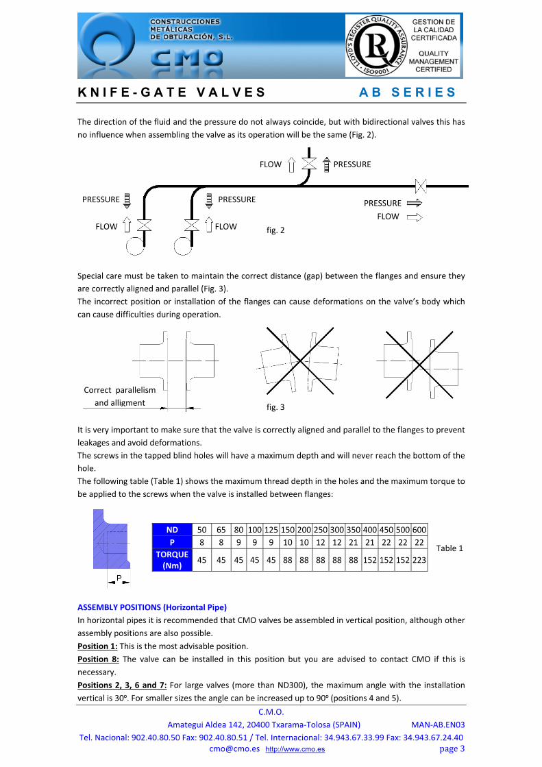
The direction of the fluid and the pressure do not always coincide, but with bidirectional valves this has
no influence when assembling the valve as its operation will be the same (Fig. 2).
Special care must be taken to maintain the correct distance (gap) between the flanges and ensure they
are correctly aligned and parallel (Fig. 3).
The incorrect position or installation of the flanges can cause deformations on the valve’s body which
can cause difficulties during operation.
It is very important to make sure that the valve is correctly aligned and parallel to the flanges to prevent
leakages and avoid deformations.
The screws in the tapped blind holes will have a maximum depth and will never reach the bottom of the
hole.
The following table (Table 1) shows the maximum thread depth in the holes and the maximum torque to
be applied to the screws when the valve is installed between flanges:
ASSEMBLY POSITIONS (Horizontal Pipe)
In horizontal pipes it is recommended that CMO valves be assembled in vertical position, although other
assembly positions are also possible.
Position 1: This is the most advisable position. Position 8: The valve can be installed in this position but you are advised to contact CMO if this is
necessary. Positions 2, 3, 6 and 7: For large valves (more than ND300), the maximum angle with the installation
vertical is 30º. For smaller sizes the angle can be increased up to 90º (positions 4 and 5).
ND 50 65 80 100 125 150 200 250 300 350 400 450 500 600
P 8 8 9 9 9 10 10 12 12 21 21 22 22 22
TORQUE (Nm)
45 45 45 45 45 88 88 88 88 88 152 152 152 223
fig. 2
fig. 3
PRESSURE
FLOW FLOW
FLOW
FLOW
PRESSURE PRESSURE
PRESSURE
Correct parallelism
and alligment
Table 1
K N I F E - G A T E V A L V E S A B S E R I E S
C.M.O.
Amategui Aldea 142, 20400 Txarama‐Tolosa (SPAIN) MAN‐AB.EN03
Tel. Nacional: 902.40.80.50 Fax: 902.40.80.51 / Tel. Internacional: 34.943.67.33.99 Fax: [email protected] http://www.cmo.es page4
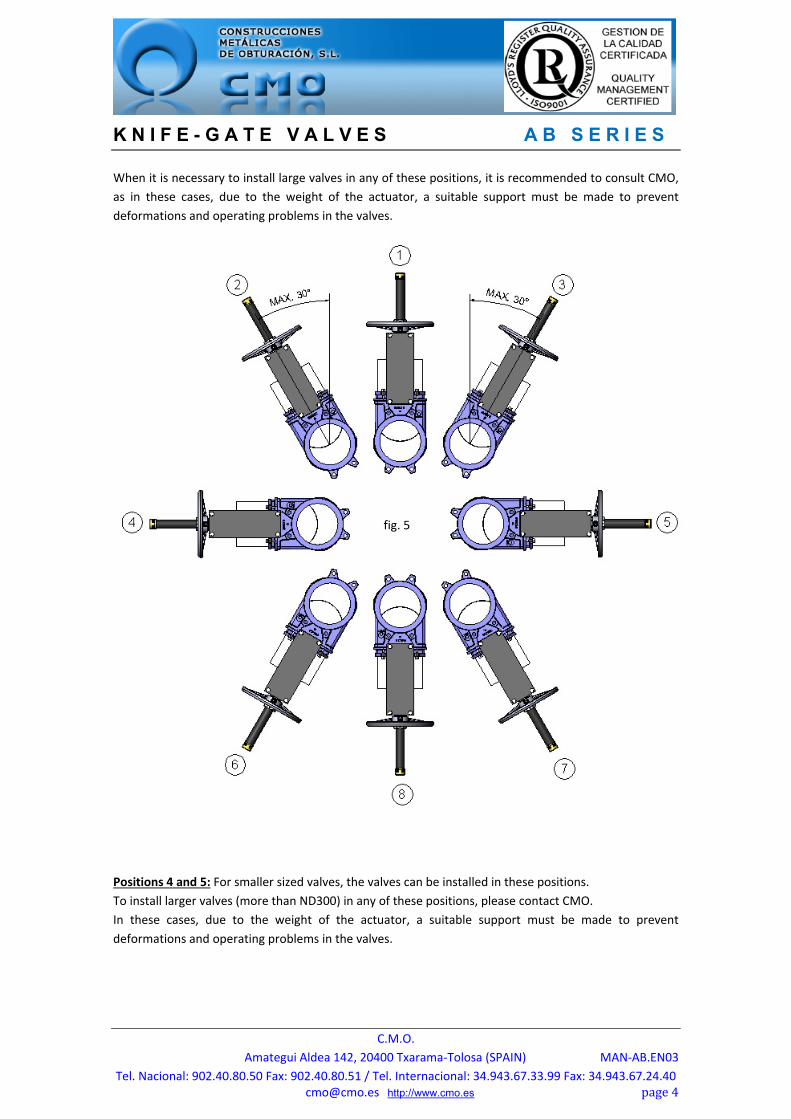
When it is necessary to install large valves in any of these positions, it is recommended to consult CMO,
as in these cases, due to the weight of the actuator, a suitable support must be made to prevent
deformations and operating problems in the valves.
Positions 4 and 5: For smaller sized valves, the valves can be installed in these positions.
To install larger valves (more than ND300) in any of these positions, please contact CMO.
In these cases, due to the weight of the actuator, a suitable support must be made to prevent
deformations and operating problems in the valves.
fig. 5
K N I F E - G A T E V A L V E S A B S E R I E S
C.M.O.
Amategui Aldea 142, 20400 Txarama‐Tolosa (SPAIN) MAN‐AB.EN03
Tel. Nacional: 902.40.80.50 Fax: 902.40.80.51 / Tel. Internacional: 34.943.67.33.99 Fax: [email protected] http://www.cmo.es page5
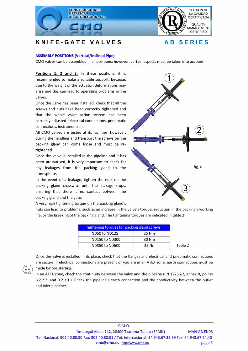
ASSEMBLY POSITIONS (Vertical/Inclined Pipe)
CMO valves can be assembled in all positions; however, certain aspects must be taken into account:
Positions 1, 2 and 3: In these positions, it is
recommended to make a suitable support, because,
due to the weight of the actuator, deformations may
arise and this can lead to operating problems in the
valves. Once the valve has been installed, check that all the
screws and nuts have been correctly tightened and
that the whole valve action system has been
correctly adjusted (electrical connections, pneumatic
connections, instruments…).
All CMO valves are tested at its facilities, however,
during the handling and transport the screws on the
packing gland can come loose and must be re‐
tightened.
Once the valve is installed in the pipeline and it has
been pressurised, it is very important to check for
any leakages from the packing gland to the
atmosphere. In the event of a leakage, tighten the nuts on the
packing gland crosswise until the leakage stops,
ensuring that there is no contact between the
packing gland and the gate. A very high tightening torque on the packing gland’s
nuts can lead to problems, such as an increase in the valve’s torque, reduction in the packing’s working
life, or the breaking of the packing gland. The tightening torques are indicated in table 2:
Once the valve is installed in its place, check that the flanges and electrical and pneumatic connections
are secure. If electrical connections are present or you are in an ATEX zone, earth connections must be
made before starting.
In an ATEX zone, check the continuity between the valve and the pipeline (EN 12266‐2, annex B, points
B.2.2.2. and B.2.3.1.). Check the pipeline’s earth connection and the conductivity between the outlet
and inlet pipelines.
Tightening torques for packing gland screws
ND50 to ND125 25 Nm
ND150 to ND300 30 Nm
ND350 to ND600 35 Nm Table 2
fig. 6
K N I F E - G A T E V A L V E S A B S E R I E S
C.M.O.
Amategui Aldea 142, 20400 Txarama‐Tolosa (SPAIN) MAN‐AB.EN03
Tel. Nacional: 902.40.80.50 Fax: 902.40.80.51 / Tel. Internacional: 34.943.67.33.99 Fax: [email protected] http://www.cmo.es page6
HANDWHEEL (Rising or Non‐Rising Stem and Stem with Gear Box)
To operate the valve: We can turn the handwheel clockwise (close) or anticlockwise (open).
CHAINWHEEL
To operate the valve pull one of the chain’s vertical drops downwards, to lock it with the other one,
taking into account that opening is clockwise.
LEVER
First loosen the position locking clamp located on the yoke. Once it is unlocked raise the lever to open or
lower it to close. To complete the operation lock the lever again.
PNEUMATIC (Double and Single Acting), HYDRAULIC (Double and Single Acting)
This actuator can be manually operated (via pushbuttons), and automatically operated via various
sensors, detectors, timers...
MOTORISED (Rising or Non‐Rising Stem and Stem with Gear Box)
This actuator can also be operated manually or automatically, each different type of actuator will have
its own instructions.
In order to avoid personal harm and other types of damage (to the plant, etc.) please follow these
recommendations:
The staff member responsible for the installation, operation and maintenance of the valves must be qualified and trained in the operation of similar valves.
Appropriate personal protection must be used (gloves, safety boots, goggles, helmet…).
Shut off all operating lines to the valve and put up a warning sign.
Completely isolate the valve from the process.
Fully depressurise the process.
Drain all the line’s fluid through the valve.
Use hand tools not electric tools during the installation and maintenance, in accordance with EN13463‐1(15).
MAINTENANCE
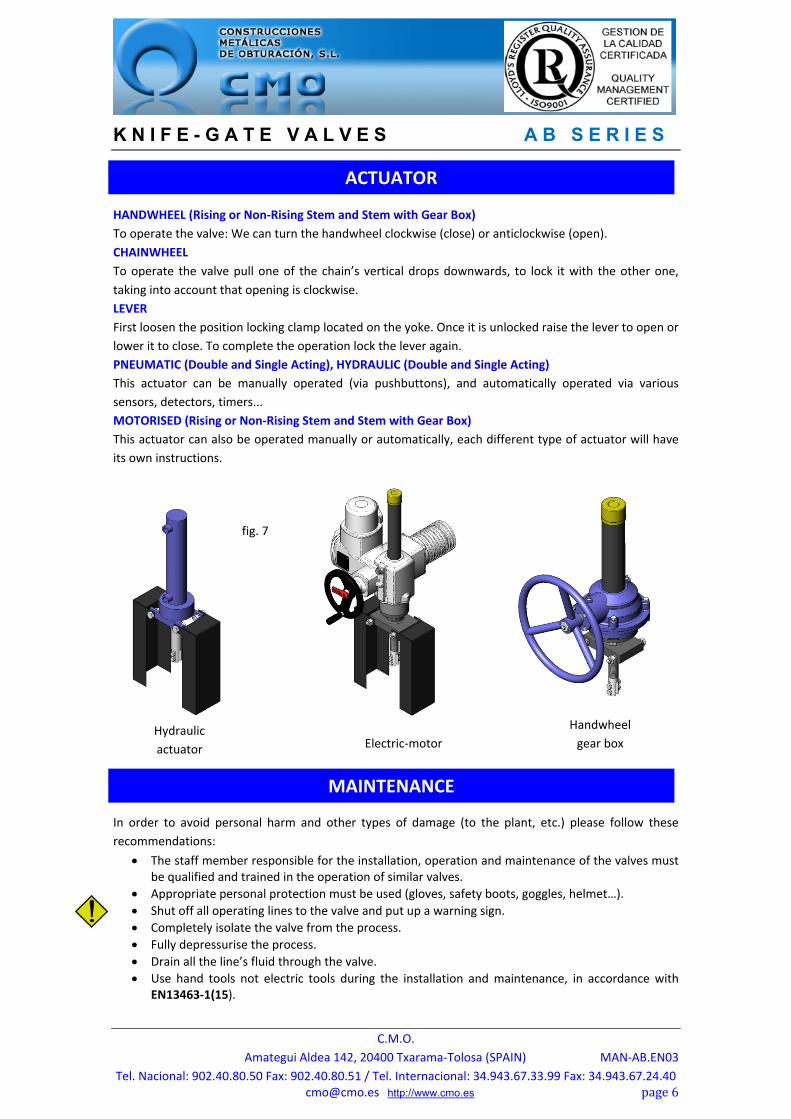
ACTUATOR
Hydraulic
actuator Electric‐motor
fig. 7
Handwheel
gear box
K N I F E - G A T E V A L V E S A B S E R I E S
C.M.O.
Amategui Aldea 142, 20400 Txarama‐Tolosa (SPAIN) MAN‐AB.EN03
Tel. Nacional: 902.40.80.50 Fax: 902.40.80.51 / Tel. Internacional: 34.943.67.33.99 Fax: [email protected] http://www.cmo.es page7
The only maintenance required in this type of valve is to change the seat’s rubber joint (if soft seated
valve is used) and the packing. It is recommended to check the seal every 6 months, however its working
life will depend on the valve’s operating conditions, such as: Pressure, temperature, number of
operations, fluid composition, among others.
In an ATEX zone, electrostatic charges may be present inside the valve, which can cause explosions. The
user is responsible for minimising the risks.
‐The maintenance staff must consider the risks of explosion and ATEX training is recommended.
‐If the fluid transported constitutes an internal explosive atmosphere, the user must regularly check the
installation’s correct watertight integrity.
‐ Regular cleaning of the valve to prevent accumulation of dust.
‐Assemblies not permitted at the end of the line.
‐Avoid painting the products supplied.
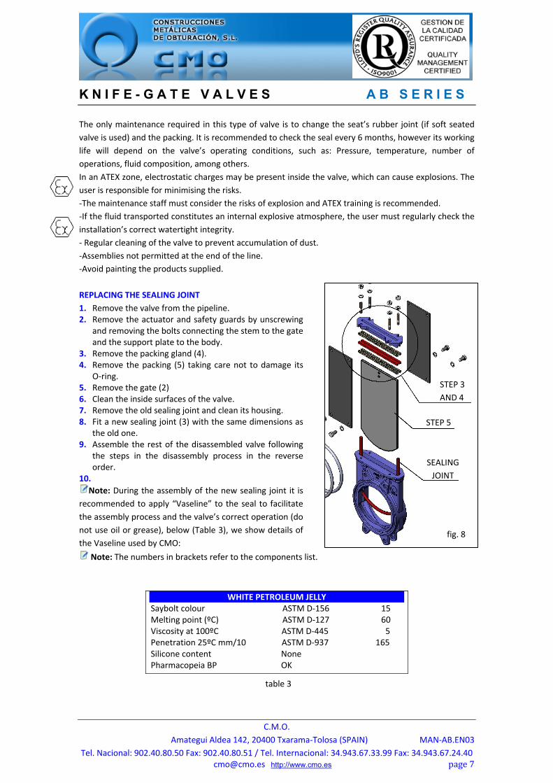
REPLACING THE SEALING JOINT
1. Remove the valve from the pipeline. 2. Remove the actuator and safety guards by unscrewing
and removing the bolts connecting the stem to the gate and the support plate to the body.
3. Remove the packing gland (4). 4. Remove the packing (5) taking care not to damage its
O‐ring. 5. Remove the gate (2) 6. Clean the inside surfaces of the valve. 7. Remove the old sealing joint and clean its housing. 8. Fit a new sealing joint (3) with the same dimensions as
the old one. 9. Assemble the rest of the disassembled valve following
the steps in the disassembly process in the reverse order.
10. Note: During the assembly of the new sealing joint it is
recommended to apply “Vaseline” to the seal to facilitate
the assembly process and the valve’s correct operation (do
not use oil or grease), below (Table 3), we show details of
the Vaseline used by CMO:
Note: The numbers in brackets refer to the components list.
WHITE PETROLEUM JELLYSaybolt colour ASTM D‐156 15 Melting point (ºC) ASTM D‐127 60 Viscosity at 100ºC ASTM D‐445 5 Penetration 25ºC mm/10 ASTM D‐937 165 Silicone content None Pharmacopeia BP OK
table 3
fig. 8
STEP 3
AND 4
STEP 5
SEALING
JOINT
K N I F E - G A T E V A L V E S A B S E R I E S
C.M.O.
Amategui Aldea 142, 20400 Txarama‐Tolosa (SPAIN) MAN‐AB.EN03
Tel. Nacional: 902.40.80.50 Fax: 902.40.80.51 / Tel. Internacional: 34.943.67.33.99 Fax: [email protected] http://www.cmo.es page8
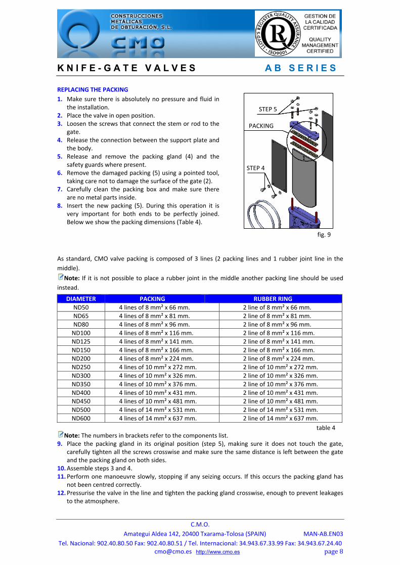
REPLACING THE PACKING
1. Make sure there is absolutely no pressure and fluid in the installation.
2. Place the valve in open position. 3. Loosen the screws that connect the stem or rod to the
gate. 4. Release the connection between the support plate and
the body. 5. Release and remove the packing gland (4) and the
safety guards where present. 6. Remove the damaged packing (5) using a pointed tool,
taking care not to damage the surface of the gate (2). 7. Carefully clean the packing box and make sure there
are no metal parts inside. 8. Insert the new packing (5). During this operation it is
very important for both ends to be perfectly joined. Below we show the packing dimensions (Table 4).
As standard, CMO valve packing is composed of 3 lines (2 packing lines and 1 rubber joint line in the
middle).
Note: If it is not possible to place a rubber joint in the middle another packing line should be used
instead.
Note: The numbers in brackets refer to the components list. 9. Place the packing gland in its original position (step 5), making sure it does not touch the gate,
carefully tighten all the screws crosswise and make sure the same distance is left between the gate and the packing gland on both sides.
10. Assemble steps 3 and 4. 11. Perform one manoeuvre slowly, stopping if any seizing occurs. If this occurs the packing gland has
not been centred correctly. 12. Pressurise the valve in the line and tighten the packing gland crosswise, enough to prevent leakages
to the atmosphere.
DIAMETER PACKING RUBBER RING
ND50 4 lines of 8 mm² x 66 mm. 2 line of 8 mm² x 66 mm.
ND65 4 lines of 8 mm² x 81 mm. 2 line of 8 mm² x 81 mm.
ND80 4 lines of 8 mm² x 96 mm. 2 line of 8 mm² x 96 mm.
ND100 4 lines of 8 mm² x 116 mm. 2 line of 8 mm² x 116 mm.
ND125 4 lines of 8 mm² x 141 mm. 2 line of 8 mm² x 141 mm.
ND150 4 lines of 8 mm² x 166 mm. 2 line of 8 mm² x 166 mm. ND200 4 lines of 8 mm² x 224 mm. 2 line of 8 mm² x 224 mm. ND250 4 lines of 10 mm² x 272 mm. 2 line of 10 mm² x 272 mm. ND300 4 lines of 10 mm² x 326 mm. 2 line of 10 mm² x 326 mm. ND350 4 lines of 10 mm² x 376 mm. 2 line of 10 mm² x 376 mm. ND400 4 lines of 10 mm² x 431 mm. 2 line of 10 mm² x 431 mm. ND450 4 lines of 10 mm² x 481 mm. 2 line of 10 mm² x 481 mm. ND500 4 lines of 14 mm² x 531 mm. 2 line of 14 mm² x 531 mm. ND600 4 lines of 14 mm² x 637 mm. 2 line of 14 mm² x 637 mm.
table 4
fig. 9
STEP 5
STEP 4
PACKING
K N I F E - G A T E V A L V E S A B S E R I E S
C.M.O.
Amategui Aldea 142, 20400 Txarama‐Tolosa (SPAIN) MAN‐AB.EN03
Tel. Nacional: 902.40.80.50 Fax: 902.40.80.51 / Tel. Internacional: 34.943.67.33.99 Fax: [email protected] http://www.cmo.es page9
table 5
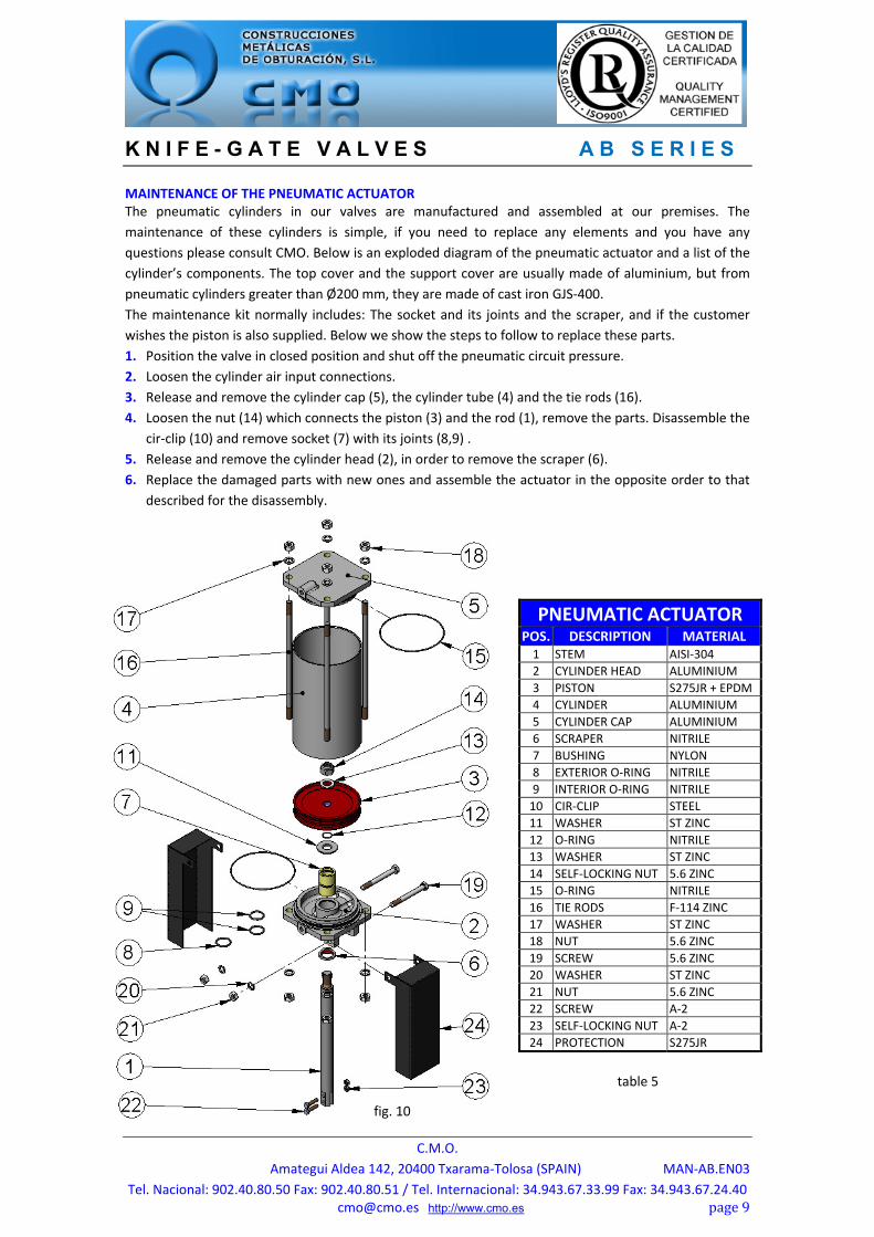
MAINTENANCE OF THE PNEUMATIC ACTUATOR The pneumatic cylinders in our valves are manufactured and assembled at our premises. The
maintenance of these cylinders is simple, if you need to replace any elements and you have any
questions please consult CMO. Below is an exploded diagram of the pneumatic actuator and a list of the
cylinder’s components. The top cover and the support cover are usually made of aluminium, but from
pneumatic cylinders greater than Ø200 mm, they are made of cast iron GJS‐400.
The maintenance kit normally includes: The socket and its joints and the scraper, and if the customer
wishes the piston is also supplied. Below we show the steps to follow to replace these parts.
1. Position the valve in closed position and shut off the pneumatic circuit pressure.
2. Loosen the cylinder air input connections.
3. Release and remove the cylinder cap (5), the cylinder tube (4) and the tie rods (16).
4. Loosen the nut (14) which connects the piston (3) and the rod (1), remove the parts. Disassemble the
cir‐clip (10) and remove socket (7) with its joints (8,9) .
5. Release and remove the cylinder head (2), in order to remove the scraper (6).
6. Replace the damaged parts with new ones and assemble the actuator in the opposite order to that
described for the disassembly.
PNEUMATIC ACTUATORPOS. DESCRIPTION MATERIAL1 STEM AISI‐304
2 CYLINDER HEAD ALUMINIUM
3 PISTON S275JR + EPDM
4 CYLINDER ALUMINIUM
5 CYLINDER CAP ALUMINIUM
6 SCRAPER NITRILE
7 BUSHING NYLON
8 EXTERIOR O‐RING NITRILE
9 INTERIOR O‐RING NITRILE
10 CIR‐CLIP STEEL
11 WASHER ST ZINC
12 O‐RING NITRILE
13 WASHER ST ZINC
14 SELF‐LOCKING NUT 5.6 ZINC
15 O‐RING NITRILE
16 TIE RODS F‐114 ZINC
17 WASHER ST ZINC
18 NUT 5.6 ZINC
19 SCREW 5.6 ZINC
20 WASHER ST ZINC
21 NUT 5.6 ZINC
22 SCREW A‐2
23 SELF‐LOCKING NUT A‐2
24 PROTECTION S275JR
fig. 10
K N I F E - G A T E V A L V E S A B S E R I E S
C.M.O.
Amategui Aldea 142, 20400 Txarama‐Tolosa (SPAIN) MAN‐AB.EN03
Tel. Nacional: 902.40.80.50 Fax: 902.40.80.51 / Tel. Internacional: 34.943.67.33.99 Fax: [email protected] http://www.cmo.es page10
LUBRICATION
It is recommended to lubricate the stem twice a year by removing the protection cap and filling it with
grease up to half its volume.
After the maintenance is complete, in an ATEX zone it is obligatory to check the electrical continuity
between the pipeline and the rest of the installation’s components. EN 12266‐2, annex B, points B.2.2.2.
and B.2.3.1.)
STORAGE
To ensure the valve is in optimum conditions of use after long periods of storage, it should be stored in a
well‐ventilated place at temperatures below 30 ºC.
It is not advisable, but if it is stored outside, the valve must be covered to protect it from heat and direct
sunlight, with good ventilation to prevent humidity. The following aspects must be considered for
storage purposes: The storage place must be dry and under cover.
It is not recommended to store the equipment outdoors with direct exposure to adverse weather conditions, such as rain, wind, etc. Even less so if the equipment is not protected with packaging.
This recommendation is even more important in areas with high humidity and saline environments.
Wind can carry dust and particles which can come into contact with the valve’s mobile parts and this
can lead to operating difficulties. The actuator system can also be damage due to the introduction of
particles in the different elements.
The equipment must be stored on a flat surface to avoid deformations.
If the equipment is stored without suitable packaging it is important to keep the valve’s mobile parts lubricated, for this reason, it is recommended to carry out regular checks and lubrication.
Likewise, if there are any machined surfaces without surface protection it is important for some form of protection to be applied to prevent the appearance of corrosion.
K N I F E - G A T E V A L V E S A B S E R I E S
C.M.O.
Amategui Aldea 142, 20400 Txarama‐Tolosa (SPAIN) MAN‐AB.EN03
Tel. Nacional: 902.40.80.50 Fax: 902.40.80.51 / Tel. Internacional: 34.943.67.33.99 Fax: [email protected] http://www.cmo.es page11
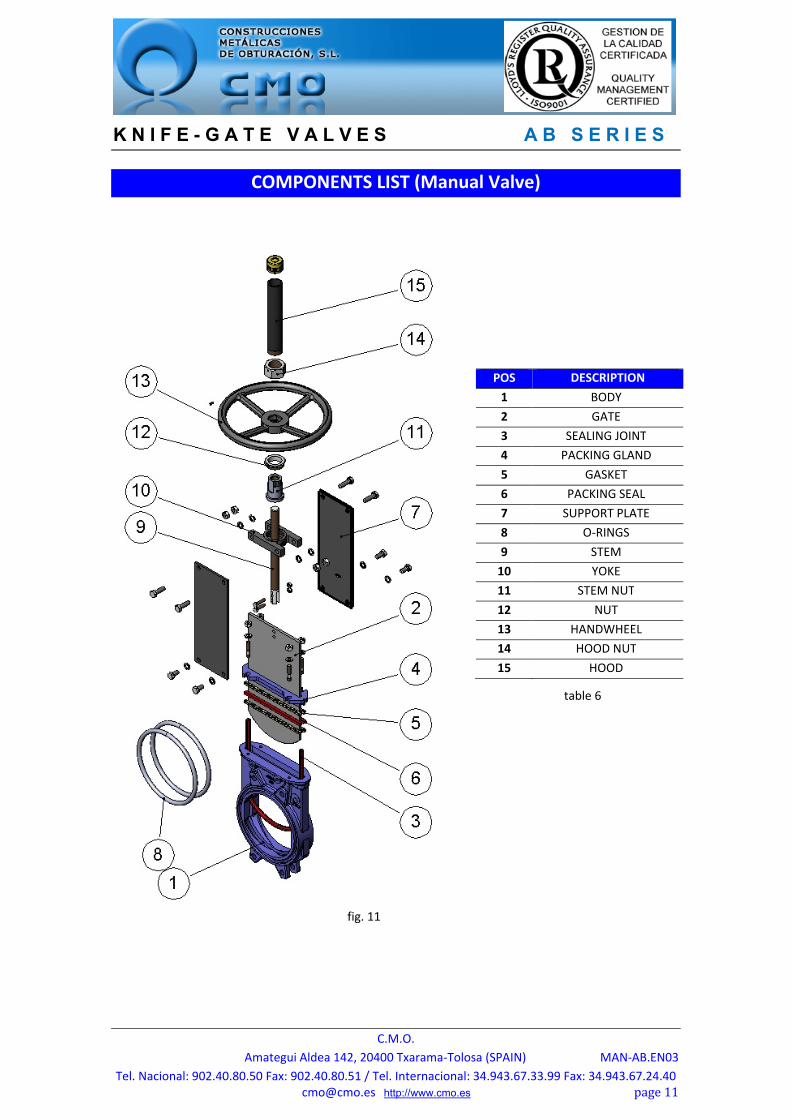
COMPONENTS LIST (Manual Valve)
POS DESCRIPTION
1 BODY
2 GATE
3 SEALING JOINT
4 PACKING GLAND
5 GASKET
6 PACKING SEAL
7 SUPPORT PLATE
8 O‐RINGS
9 STEM
10 YOKE
11 STEM NUT
12 NUT
13 HANDWHEEL
14 HOOD NUT
15 HOOD
fig. 11
table 6