CAPACITACIÓN TÉCNICA DE...
23
SmartWAVE® CAPACITACIÓN TÉCNICA DE BUNN®
Transcript of CAPACITACIÓN TÉCNICA DE...

SmartWAVE®
CAPACITACIÓN TÉCNICA DE BUNN®


Índice
Unidad 1: Instalación
Requisitos del sitio ................................................................................ 5Ubicación del número de serie ............................................................. 5Instalación del suministro de agua ...................................................... 5Instalación eléctrica ............................................................................... 6Configuración inicial .............................................................................. 6
Unidad 2: Configuración
Configuración y programación ............................................................. 8Programación de SmartWAVE digital ....................................... 8Programación de SmartWAVE serie Silver .............................. 10
Interruptores del programa ................................................................... 11
Unidad 3: Composición de la máquina
Descripción general del exterior .......................................................... 13Tomacorrientes y piezas desmontables del producto ............ 13Interfaz de usuario ..................................................................... 13
Acceso al interior de la cafetera ........................................................... 13Funciones y operaciones de la máquina ............................................. 14
Tablero de control principal ...................................................... 14Sistema de llenado ..................................................................... 14Sistema de calentamiento ......................................................... 14Sistema dispensador ................................................................. 15
Unidad 4: Mantenimiento preventivo
Mantenimiento preventivo ..................................................................... 17Pasos del mantenimiento preventivo ................................................... 17
Unidad 5: Resolución de problemas
Vaciado del tanque ................................................................................. 19Códigos de fallas del servicio: SmartWAVE digital ............................ 19Códigos de fallas del servicio: SmartWAVE serie Silver .................... 19Resolución de problemas ..................................................................... 19
Sistema de llenado ..................................................................... 20Sistema de calentamiento ......................................................... 20Sistema de preparación ............................................................. 21
Objetivos de la unidad
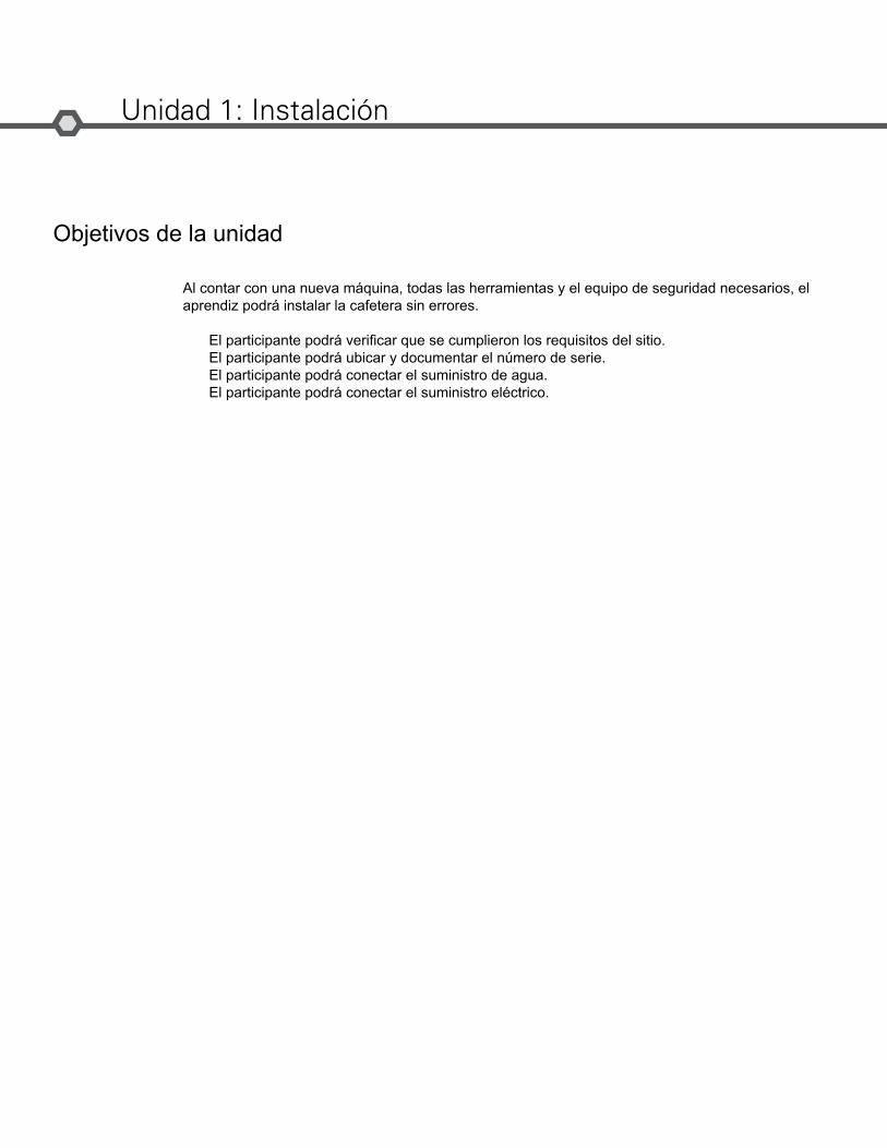
Unidad 1: Instalación
Al contar con una nueva máquina, todas las herramientas y el equipo de seguridad necesarios, el aprendiz podrá instalar la cafetera sin errores.
El participante podrá verificar que se cumplieron los requisitos del sitio.El participante podrá ubicar y documentar el número de serie.El participante podrá conectar el suministro de agua.El participante podrá conectar el suministro eléctrico.
Bunn-O-Matic Corporation5
Instalación
Requisitos del sitio
Espacio
• Altura libre de 19 pulgadas• Ocupa una superficie de 10 pulgadas de ancho x 18 pulgadas de profundidad• Superficie de apoyo con capacidad para soportar 25 lb• Superficie de instalación nivelada, cafetera nivelada en la superficie
Tratamiento del agua
• Filtración de sedimentos para reducir partículas grandes• Filtro de sabor y olor para eliminar el cloro• Inhibidor de sarro, según se requiera• Para obtener mejores resultados, se debe usar el sistema de filtrado BUNN Easy Clear
Conexión de tubería
• Conector de 0.75-11.5 NH (rosca de 3/4 pulgadas) (adaptador acodado de 1/4 pulgadas incluido)• Suministro de agua dedicado con apagado• Conectado al suministro de agua fría• Presión del agua de 20 a 90 psi
Conexión eléctrica (120 VCA)
• 120 VCA• 2 cables y tierra (L1, neutro, tierra)• Circuito dedicado de 15 A (interruptor, enchufe y receptáculo)• Receptáculo a 5 pulgadas de la máquina• Cable de alimentación y enchufe incluidos
Conexión eléctrica (208 VCA o 240 VCA)
• 120/208 VCA o 120/240 VCA• 3 cables y tierra (L1, L2, neutro, tierra)• Circuito dedicado de 15 A (interruptor, enchufe y receptáculo)• Receptáculo a 5 pulgadas de la máquina
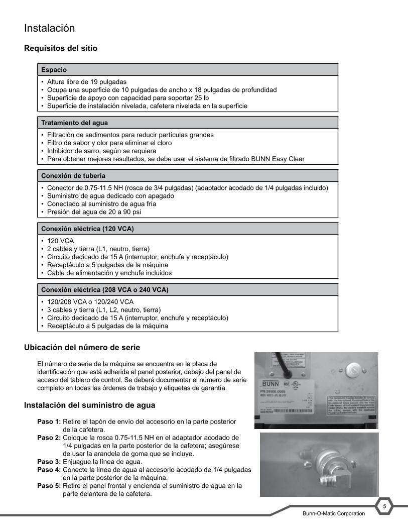
Ubicación del número de serie
El número de serie de la máquina se encuentra en la placa de identificación que está adherida al panel posterior, debajo del panel de acceso del tablero de control. Se deberá documentar el número de serie completo en todas las órdenes de trabajo y etiquetas de garantía.
Instalación del suministro de agua
Paso 1: Retire el tapón de envío del accesorio en la parte posterior de la cafetera.
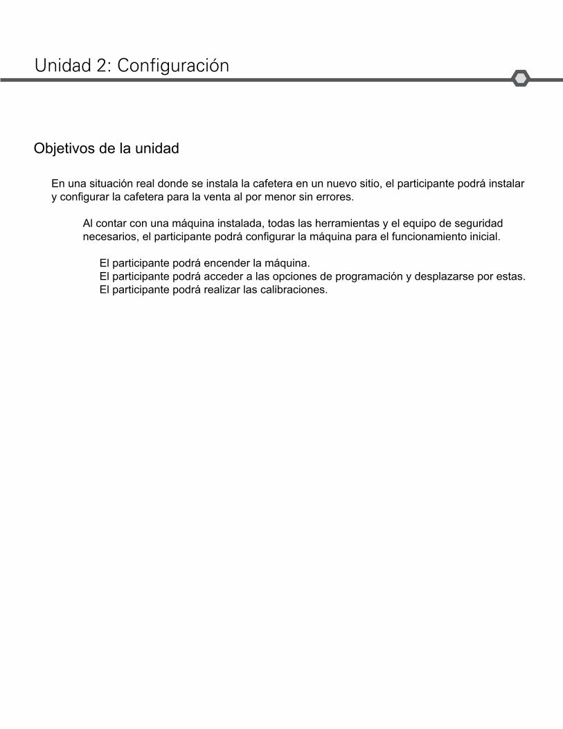
Paso 2: Coloque la rosca 0.75-11.5 NH en el adaptador acodado de 1/4 pulgadas en la parte posterior de la cafetera; asegúrese de usar la arandela de goma que se incluye.
Paso 3: Enjuague la línea de agua.Paso 4: Conecte la línea de agua al accesorio acodado de 1/4 pulgadas
en la parte posterior de la máquina.Paso 5: Retire el panel frontal y encienda el suministro de agua en la
parte delantera de la cafetera.
SmartWAVE® Training Manual4
Installation
Site Requirements
Space
Height clearance of 19”•Footprint able to accommodate 10” W x 18” D•Counter able to support 25lbs•Level installation surface, brewer level on the surface•
Water Treatment
Sedimentfiltrationtoreducelargeparticles•Tasteandodorfiltertoremovechlorine•Scalefiltrationasneeded•For best results a BUNN• ® Easy Clear®filtrationsystemshouldbeused
Plumbing
.75-11.5NH(3/4”hosethread)fitting(¼”flareadapterincluded)•Dedicated water supply with shut-off•Connected to the cold water supply•Water pressure 20-90 psi•
Electrical (120VAC)
120VAC•2-wire plus ground (L1, neutral, ground)•15 amp dedicated circuit (breaker, plug, and receptacle)•Receptacle within 5 feet of the machine•Power cord and plug included•
Electrical (208VAC or 240VAC)
120/208VAC or 120/240VAC•3-wire plus ground (L1, L2, neutral, ground)•15 amp dedicated circuit (breaker, plug, and receptacle)•Receptacle within 5 feet of the machine•
Location of the Serial Number
The machine’s serial number is located on the data plate which is adhered to the rear panel below the control board access panel. The complete serial number will need to be documented on all work orders and warranty tags.
Water Supply Install
Step 1:RemovetheshippingcapfromthefittingontherearofthebrewerStep 2:Installthe.75-11.5NHto¼”flareadapterontherearofthebrewer;be sure to use the included rubber washer.Step 3: Flush the water line.Step 4:Attachthewaterlinetothe¼”flarefittingonthebackofthema-chine.Step 5: Turn on the water supply

Manual de capacitación de ITCB6
Instalación eléctrica
Un electricista debe proveer servicio eléctrico según se especifica conforme a los códigos eléctricos locales, estatales y federales.
La cafetera SmartWAVE® está disponible como una unidad configurada para 120 VCA o 120/208-120/240 VCA. Asegúrese de que el lugar cuente con los requisitos eléctricos adecuados para la cafetera que instalará. Consulte la placa de identificación de la cafetera para obtener las especificaciones eléctricas.
Para cafeteras de 120 VCA:Paso 1: Enchufe la cafetera a una fuente de alimentación.
Para cafeteras de 120/208 VCA o 120/240 VCA:Paso 1: Retire el panel de acceso al bloque terminal en la parte posterior de la cafetera.Paso 2: Alimente el cable a través del dispositivo de alivio de tensión.Paso 3: Conecte los extremos del cable al bloque terminal y el cable de tierra a la masa del chasis.Paso 4: Ajuste el dispositivo de alivio de tensión y vuelva a colocar el panel de acceso.Paso 5: Instale la tapa para enchufe en el extremo opuesto del cable de alimentación.Paso 6: Conecte la cafetera a la fuente de alimentación.Paso 7: Encienda el interruptor principal.
Arranque inicial
Una vez que la cafetera se conecta a la fuente de alimentación o se enciende (según el modelo), presione el interruptor ENABLE BREW ON/OFF (ACTIVAR PREPARACIÓN DEL CAFÉ ENCENDIDO/APAGADO). El agua comenzará a fluir dentro del tanque y se detendrá cuando el tanque se llene. El agua puede gotear un poco del cabezal de rociado debido a la expansión.
Después de llenar el tanque, la máquina comenzará automáticamente el ciclo de calentamiento. Esto demorará aproximadamente 20 minutos.
Una vez que el agua alcanza la temperatura programada, aparecerá el mensaje READY (LISTO) en la pantalla (luz verde en la serie Silver).
Bunn-O-Matic Corporation5
Electrical Install
An electrician must provide electrical service as specified in conformance with all local, state, and federal electrical codes.
The SmartWAVE® brewer is available as either a 120VAC or 120/208-120/240VAC configured unit. Ensure the loca-tion has the appropriate electrical requirements for the brewer being installed. Always refer to the brewer’s data plate for electrical specifications.
For 120VAC Brewers:Step 1: Plug brewer into the power source.
For 120/208VAC or 120/240VAC Brewers:Step 1: Remove the terminal block access panel on the rear of the brewer.Step 2: Feed the power cord through the strain relief.Step 3: Connect the wire ends to the terminal block and the ground wire to the chassis ground.Step 4: Tighten the strain relief and reinstall the access panel.Step 5: Install the cord cap onto the opposite end of the power cord.Step 6: Connect the brewer to the power source.Step 7: Turn the main power switch on.
Initial Start-Up
After the brewer is connected to the power source or turned on (depending on model) press the ENABLE BREW ON/OFF switch. Water will begin to flow into the tank and stop when the tank is full. Some water may drip from the sprayhead due to expansion.
After the tank fills the machine will automatically begin the heating cycle. This will take approximately 20 minutes.
Once the water temperature has reached the programmed temperature READY will scroll across the screen (green light on Silver series).
TM
Enable Brew
TM
Enable Brewactivar preparación Manual de capacitación de ITCB
Objetivos de la unidad
Unidad 2: Configuración
En una situación real donde se instala la cafetera en un nuevo sitio, el participante podrá instalar y configurar la cafetera para la venta al por menor sin errores.
Al contar con una máquina instalada, todas las herramientas y el equipo de seguridad necesarios, el participante podrá configurar la máquina para el funcionamiento inicial.
El participante podrá encender la máquina.El participante podrá acceder a las opciones de programación y desplazarse por estas.El participante podrá realizar las calibraciones.

Manual de capacitación de ITCB8
Configuración y programaciónA través del panel de la interfaz de usuario se puede acceder a las funciones de programación de la cafetera y usarlas sin herramientas especiales.
La configuración del volumen y flujo del agua de la cafetera SmartWAVE® se preestableció en fábrica. Se puede aumentar o disminuir el volumen, o también se puede programar el parámetro de preparación intermitente. Además, hay cuatro interruptores DIP de programación ubicados en el tablero de control.
Programación de SmartWAVE® digital
Nivel 1 de programación
El Nivel 1 de programación contiene las opciones de programación para los parámetros del producto. Para acceder al nivel 1 se debe presionar el interruptor oculto durante 5 segundos.
Los dos botones de preparación permiten almacenar dos recetas o tandas diferentes en la cafetera. Cada botón tiene tres configuraciones diferentes que pueden personalizarse según los requisitos específicos del cliente:
• Tiempo de preparación: tiempo requerido para lograr el volumen de preparación deseado.• Configuración de preparación intermitente: la cantidad de “impulsos” deseados. Durante un “impulso”, la
máquina detiene la función de preparación para que drene el portafiltro.• Tiempo de goteo: el tiempo después de la preparación durante el cual el portafiltro drena el líquido en la jarra
antes de que este deba retirarse de la máquina.
Botón de preparación A* Predeterminado Mínimo Máximo Incrementos de ajusteA1: Tamaño de tanda (tiempo) 2:05 0.26 5:00 SegundosA2: BrewMETER (ciclos de
preparación intermitente)1 1 14 1-14 segundos
A3: Goteo (tiempo) 1:00 0.05 5:00 5 segundos* Los valores son los mismos para el Botón de preparación B.
Al programar la cafetera SmartWAVE® es importante saber qué tipo de recipiente usará el cliente para establecer el tamaño de la tanda. La cafetera admite una variedad de jarras y termos. Si bien en la cafetera cabe un termo de 3.0 L, el recipiente más grande que se recomienda utilizar en la SmartWAVE® es un termo de 2.5 L debido al tamaño del tanque de la máquina.
1 Interruptor oculto2 Pantalla3 Brew A (Preparación A) (-)4 Brew B (Preparación B) (+)
Paso 1: Presione el botón oculto hasta que aparezca A1 en la pantalla. Esto representa el modo de ajuste del Tiempo de preparación para el interruptor de preparación A. La pantalla alternará entre A1 y la configuración. Presione el botón Brew A (Preparación A) para disminuir el tiempo o el botón Brew B (Preparación B) para aumentarlo.
Bunn-O-Matic Corporation7
Setup and Programming
Accessing and using the brewer’s programming features is done from the user interface panel and requires no spe-cial tools.
Water volumes and flow settings for the SmartWAVE® brewer have been preset at the factory. The volumes can be increased or decreased and optional pulse brewing can be programmed. Additionally there are four programming dip switches located on the control board.
Programming Digital SmartWAVE®
Level 1 Programming
Level 1 programming contains the programming options for the product parameters. Access to level 1 is done by pressing the hidden switch for 5 seconds.
The two brew buttons allow for two different recipes and/or batch sizes to be stored on the brewer. Each button has three different settings than can be tuned to specific customer requirements:
Brew Time: the time required in order to achieve the desired brew volume.•Pulse Brew setting: the number of desired “pulses.” During a “pulse” the machine cycles the brew function off, •
allowing the funnel to drain.Drip Out time: the time after the brew that the funnel is draining into the server before the funnel should be re •
moved from the machine.
Brew Button A* Default Minimum Maximum Adjustment IncrementsA1: Batch Size (time) 2:05 0:26 5:00 SecondsA2: BrewMeter(pulse brew cycles) 1 1 14 1-14A3: Drip out (time) 1:00 0:05 5:00 5 second
* Values are the same for Brew Button B
When programming the SmartWAVE® brewer It is important to know what type of holding vessel the customer will be using in order to set batch sizes. The brewer can accept a variety of airpots and carafes. Even though the brewer’s clearance can accomodate a 3.0 L airpot, the largest vessel recommended for use with the SmartWAVE® is a 2.5 L airpot due to the size of the machine’s tank.
1 Hidden switch2 Display3 Brew A ( - )4 Brew B (+)
Step 1: Press the hidden switch until the display reads A1. This represents the adjust mode Brew Time for the A brew switch. The display will toggle between A1 and the setting. Press the BREW A button to decrease time or the BREW B button to increase time.Step 2: Press the hidden switch until the display reads A2. This represents the adjust mode Brew Meter (Pulse Brew) for the A brew switch. The display will toggle between A2 and the setting. The brewer has 14 preset pulse brew
TM
1 2 3 4

Bunn-O-Matic Corporation9
Paso 2: Presione el botón oculto hasta que aparezca A2 en la pantalla. Esto representa el modo de ajuste de Medidor de preparación (preparación intermitente) para el interruptor de preparación A. La pantalla alternará entre A2 y la configuración. Se pueden elegir entre las 14 rutinas de preparación intermitente preestablecidas en la cafetera. El valor predeterminado de fábrica es 1; el 14 es el valor máximo. Presione BREW A (PREPARACIÓN A) para disminuirlo o BREW B (PREPARACIÓN B) para aumentarlo.
Paso 3: Presione y suelte el interruptor oculto hasta que se muestre A3 en la pantalla. Esto representa el modo de ajuste del Tiempo de goteo para el interruptor de preparación A. La pantalla alternará entre A3 y la configuración. Presione el botón BREW A (PREPARACIÓN A) para disminuir el tiempo o el botón BREW B (PREPARACIÓN B) para aumentarlo.
Paso 4: Repita los pasos del 1 al 3 para configurar el interruptor de preparación B.
Nivel 2 de programación
El Nivel 2 de programación contiene algunos de los parámetros de la máquina. Los parámetros adicionales se configuran en el tablero de control mediante los interruptores DIP. Para acceder al nivel 2 se debe presionar el interruptor oculto durante 10 segundos.
Opción Predeterminado Mínimo Máximo Incrementos de ajusteP1: Punto de ajuste de temperatura 200 185 205 1 gradoP2: Temperatura lista 195 180 198 1 gradoP3: Visualización del nro.
de preparaciones0 0 9999 N/C
P4: Fahrenheit o Celsius F N/C
Nivel 3 de programación
El Nivel 3 de programación contiene 8 menús, que incluyen los menús de calibración y configuración de fábrica para los pasos de secuencia que se usan en un ciclo de preparación WAVE. Para acceder al nivel 3 se debe presionar el interruptor oculto durante 15 segundos.
U1: Esta pantalla no puede ajustarse; sin embargo, muestra el número de la condición del agua actual cuando el agua entra en contacto con la sonda. Rango: 0/sonda de llenado abierta, 232/sonda de llenado cortocircuitada.U2: Calibración del umbral de llenado de agua. Valor predeterminado: 85. Rango de ajuste: 30 – 220Esta pantalla se usa para establecer la sensibilidad del circuito de llenado, que puede ajustarse según las diferentes condiciones del agua. Aumente el número predeterminado para el agua muy blanda. El número relativo de la condición del agua se puede ver en el menú U1 cuando el agua entra en contacto con la sonda de llenado.U3 a U7: Menús de configuración de fábrica. Advertencia: ¡No ajustar!U8: Menú de calibración del sensor de temperatura.Esta pantalla se usa para calibrar la lectura del termistor y CBA a la temperatura actual.
Restablecer valores predeterminados de fábricaPaso 1: Desenchufe la cafetera.Paso 2: Presione el interruptor ENABLE BREW ON/OFF (ACTIVAR PREPARACIÓN ENCENDIDO/APAGADO)
y enchufe la cafetera a la fuente de alimentación.Paso 3: Presione el interruptor ENABLE BREW ON/OFF (ACTIVAR PREPARACIÓN ENCENDIDO/APAGADO)
durante 10 segundos. Durante esos 10 segundos, se encenderán las opciones centrales en la pantalla. Después de los 10 segundos, las tres opciones superior, central e inferior en la pantalla se iluminarán durante 5 segundos. Durante esos 5 segundos, suelte y vuelva a presionar el interruptor ENABLE BREW ON/OFF (ACTIVAR PREPARACIÓN ENCENDIDO/APAGADO) para restablecer la configuración predeterminada. En la pantalla aparecerá la opción DONE (TERMINADO).
Manual de capacitación de ITCB10
Si no puede acceder a la programación significa que el interruptor DIP de bloqueo de programación está en la posición ON (ENCENDIDO). El interruptor se encuentra en el tablero de control. Retire el panel de acceso del tablero de control, ubique el interruptor y colóquelo en la posición OFF (APAGADO).
Programación de SmartWAVE® serie Silver
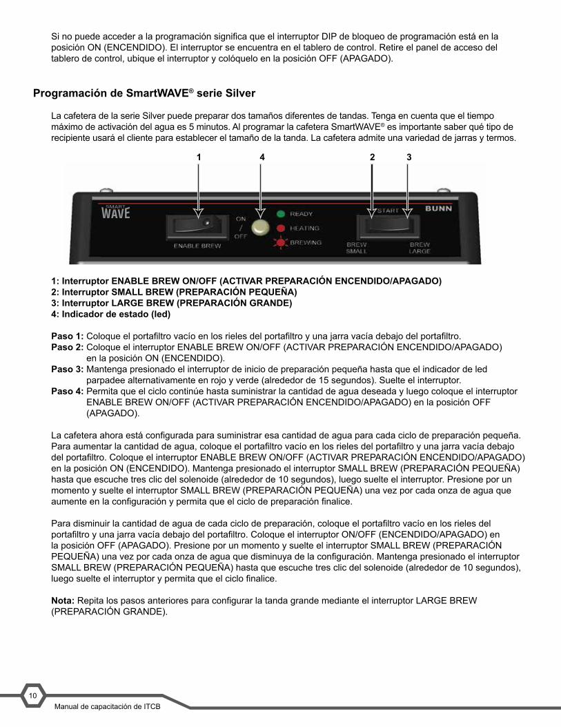
La cafetera de la serie Silver puede preparar dos tamaños diferentes de tandas. Tenga en cuenta que el tiempo máximo de activación del agua es 5 minutos. Al programar la cafetera SmartWAVE® es importante saber qué tipo de recipiente usará el cliente para establecer el tamaño de la tanda. La cafetera admite una variedad de jarras y termos.
1: Interruptor ENABLE BREW ON/OFF (ACTIVAR PREPARACIÓN ENCENDIDO/APAGADO)2: Interruptor SMALL BREW (PREPARACIÓN PEQUEÑA)3: Interruptor LARGE BREW (PREPARACIÓN GRANDE)4: Indicador de estado (led)
Paso 1: Coloque el portafiltro vacío en los rieles del portafiltro y una jarra vacía debajo del portafiltro.Paso 2: Coloque el interruptor ENABLE BREW ON/OFF (ACTIVAR PREPARACIÓN ENCENDIDO/APAGADO)
en la posición ON (ENCENDIDO).Paso 3: Mantenga presionado el interruptor de inicio de preparación pequeña hasta que el indicador de led
parpadee alternativamente en rojo y verde (alrededor de 15 segundos). Suelte el interruptor.Paso 4: Permita que el ciclo continúe hasta suministrar la cantidad de agua deseada y luego coloque el interruptor
ENABLE BREW ON/OFF (ACTIVAR PREPARACIÓN ENCENDIDO/APAGADO) en la posición OFF (APAGADO).
La cafetera ahora está configurada para suministrar esa cantidad de agua para cada ciclo de preparación pequeña. Para aumentar la cantidad de agua, coloque el portafiltro vacío en los rieles del portafiltro y una jarra vacía debajo del portafiltro. Coloque el interruptor ENABLE BREW ON/OFF (ACTIVAR PREPARACIÓN ENCENDIDO/APAGADO) en la posición ON (ENCENDIDO). Mantenga presionado el interruptor SMALL BREW (PREPARACIÓN PEQUEÑA) hasta que escuche tres clic del solenoide (alrededor de 10 segundos), luego suelte el interruptor. Presione por un momento y suelte el interruptor SMALL BREW (PREPARACIÓN PEQUEÑA) una vez por cada onza de agua que aumente en la configuración y permita que el ciclo de preparación finalice.
Para disminuir la cantidad de agua de cada ciclo de preparación, coloque el portafiltro vacío en los rieles del portafiltro y una jarra vacía debajo del portafiltro. Coloque el interruptor ON/OFF (ENCENDIDO/APAGADO) en la posición OFF (APAGADO). Presione por un momento y suelte el interruptor SMALL BREW (PREPARACIÓN PEQUEÑA) una vez por cada onza de agua que disminuya de la configuración. Mantenga presionado el interruptor SMALL BREW (PREPARACIÓN PEQUEÑA) hasta que escuche tres clic del solenoide (alrededor de 10 segundos), luego suelte el interruptor y permita que el ciclo finalice.
Nota: Repita los pasos anteriores para configurar la tanda grande mediante el interruptor LARGE BREW (PREPARACIÓN GRANDE).
Bunn-O-Matic Corporation9
1 Enable Brew On/Off Switch2 Small Brew Switch3 Large Brew Switch4 Status Indicator (LED)
Step 1: Place an empty funnel in the funnel rails and an empty server beneath the funnel.Step 2: Press the ENABLE BREW ON/OFF switch placing it in the ON position.Step 3: Press and hold the small brew start switch until the LED indicator alternately flashes red/green (approximate-ly 15 seconds). Release the switch.Step 4: Allow the cycle to continue until the desired amount of water is dispensed and then press the ENABLE BREW ON/OFF to turn OFF the brewer.
The brewer is now set to dispense this amount of water for each small brew cycle. To increase the amount of water, place an empty funnel in the funnel rails and an empty server beneath the funnel. Press the ENABLE BREW ON/OFF switch ON. Press and hold the small BREW switch until you hear the solenoid click three times (approximately 10 seconds), then release the switch. Momentarily press and release the small BREW switch once for each ounce of water to be added to the setting and allow the brew cycle to finish.
To decrease the amount of water for each brew cycle, place an empty funnel in the funnel rails and an empty server beneath the funnel. Press the ON/OFF” switch ON. Momentarily press and release the small BREW switch once for each ounce of water to be removed from the setting. Press and hold the small BREW switch until you hear the sole-noid click three times (approximately 10 seconds), then release the switch and allow the cycle to finish.
Note: Repeat the steps above to set the large batch by using the large brew switch.
Optional Pulse Brew SetupNote: Set small and large batches separately. Brewer has 4 preset pulse brew routines to choose from. Factory de-fault is 1 with 4 being the maximum time.
Step 1: With the machine off, press the small or large switch for 10 seconds. Red LED will flash to indicate current setting (1 – 4).Step 2: Press the same switch the number of times (1 – 4) for the desired setting. After 5 seconds the red LED will resume flashing the selected number.
When no switches are pressed for 30 seconds, the mode will exit. Or the mode may be exited by pressing the EN-ABLE BREW ON/OFF switch. Repeat above procedure with the other brew switch.
Note: No other additional settings are available on the Silver Series.
Restore Factory DefaultsStep 1: Unplug the brewer.Step 2: Press the ENABLE BREW ON/OFF in the On position and plug the brewer into the power source.Step 3: Press the ENABLE BREW ON/OFF switch for 10 seconds. During those 10 seconds, the red LED will be on steady. After 10 seconds the green LED will begin flashing rapidly for 5 seconds. During those 5 seconds, release and again momentarily press the ENABLE BREW ON/OFF switch again to restore default settings. The LED will alternate rapidly Red and Green for a few seconds indicating the restore has been accomplished.
TM
1 2 34

Bunn-O-Matic Corporation11
Configuración opcional de preparación intermitenteNota: Configure las tandas grandes y pequeñas por separado. Se pueden elegir entre las 4 rutinas de preparación intermitente preestablecidas en la cafetera. El valor predeterminado de fábrica es 1; el 4 es el valor máximo.
Paso 1: Con la máquina apagada, presione el interruptor de preparación pequeña o grande durante 10 segundos. El led rojo parpadeará para indicar la configuración actual (1 a 4).
Paso 2: Presione el mismo interruptor la cantidad de veces necesarias (1 a 4) para establecer la configuración deseada. Después de 5 segundos, el led rojo reanudará el parpadeo para el número seleccionado.
Cuando no se presione ningún interruptor durante 30 segundos, se saldrá de ese modo. De lo contrario, se puede salir del modo presionando el interruptor ENABLE BREW ON/OFF (ACTIVAR PREPARACIÓN ENCENDIDO/APAGADO). Repita el procedimiento anterior con el otro interruptor de preparación.
Nota: La serie Silver no cuenta con ninguna otra configuración adicional.
Restablecer valores predeterminados de fábricaPaso 1: Desenchufe la cafetera.Paso 2: Coloque el interruptor ENABLE BREW ON/OFF (ACTIVAR PREPARACIÓN ENCENDIDO/APAGADO) en la
posición ON (ENCENDIDO) y enchufe la cafetera a la fuente de alimentación.Paso 3: Presione el interruptor ENABLE BREW ON/OFF (ACTIVAR PREPARACIÓN ENCENDIDO/APAGADO)
durante 10 segundos. Durante esos 10 segundos, el led rojo permanecerá encendido. Después de los 10 segundos, el led verde comenzará a parpadear rápidamente durante 5 segundos. Durante esos 5 segundos, suelte y vuelva a presionar por un momento el interruptor ENABLE BREW ON/OFF (ACTIVAR PREPARACIÓN ENCENDIDO/APAGADO) para restablecer la configuración predeterminada. El led alternará rápidamente entre rojo y verde durante unos segundos para indicar que se completó el restablecimiento.
Interruptores del programa
Hay 4 interruptores DIP en el tablero de control que controlan las configuraciones opcionales de la cafetera SmartWAVE®. Todos estos interruptores se configuran en la posición OFF (APAGADO) de fábrica.
Nro. interruptor Función (posición OFF [APAGADO])
Función (posición ON [ENCENDIDO])
1: Bloqueo del programa Programación habilitada
Programación bloqueada
2: Bloqueo de la preparación
Preparación a cualquier temp
Solo preparaciones a temperatura lista
3: Ahorro de energía Ahorro de energía apagado
Mantiene 140 grados después de 6 horas, se apaga después de 26 horas
4: Altitud alta Establece la temp. del tanque en 200 grados
Establece la temp. del tanque en 190 grados
SmartWAVE® Training Manual10
Program Switches
There are 4 dip switches located on the control board that control optional settings on the SmartWAVE® brewer. All of these switches are set to the OFF position from the factory.
Switch # Function- Off position Function- On position1 Program Lockout Programming allowed Programming locked out2 Brew Lockout Brew at any temperature Only brews at Ready
temperature3 Energy Save Energy save mode off Maintains 140° F after
6 hours, Off after 26 hours
4 High Altitude Set tank temp. 200° F Set tank temp at 190° F
1 2
3 4
OFF
ON
Objetivos de la unidad
Unidad 3: Composición de la máquina
En una situación realista donde el participante tiene acceso a los componentes internos de la máquina, el partici-pante comprenderá la composición y las funciones de la cafetera.
En una situación realista que requiere que el participante acceda a los componentes internos de la máquina, el participante podrá retirar la cubierta, el panel superior y el panel de acceso del tablero de control.
El participante retirará la cubierta, el panel superior y el panel de acceso del tablero de control.
En una máquina operativa, el participante podrá dar una explicación general sobre cómo funciona la unidad.
El participante podrá identificar las funciones del tablero de control principal.El participante podrá identificar los componentes y las funciones del sistema de llenado.El participante podrá identificar los componentes y las funciones del sistema de calentamiento.El participante podrá identificar los componentes y las funciones del sistema dispensador.

Bunn-O-Matic Corporation13
Composición de la máquina
Descripción general del exterior
Tomacorrientes y piezas desmontables del producto
• Interfaz de usuario (1)• Salida del agua caliente (2)• Cabezal de rociado (3)• Base para jarra ajustable (4)• Patas ajustables (5)
Interfaz de usuario
El panel de control de la cafetera SmartWAVE® incluye interruptores de membrana y una pantalla alfanumérica.
A. Interruptor ENABLE BREW ON/OFF (ACTIVAR PREPARACIÓN ENCENDIDO/APAGADO)B. Interruptor BREW A (PREPARACIÓN A)C. Interruptor BREW B (PREPARACIÓN B)D. Interruptor de programación ocultoE. Pantalla
El panel de control de SmartWAVE® serie Silver incluye interruptores mecánicos y luces de led de estado.
A. Interruptor ENABLE BREW ON/OFF (ACTIVAR PREPARACIÓN ENCENDIDO/APAGADO)
B. Interruptor de tanda pequeñaC. Interruptor de tanda grandeD. Indicador de estado
Luz verde fija: lista para preparar Luz roja fija: calentamiento del tanque Luz roja parpadeante: preparación
Acceso al interior de la cafetera
La mayor parte del servicio de mantenimiento de la cafetera SmartWAVE® requerirá que se retire el panel superior, la cubierta frontal o el panel de acceso del tablero de control en la parte posterior. El panel superior está asegurado con 2 tornillos Phillips. El panel posterior está asegurado con 6 tornillos de cabeza plana y el panel posterior está asegurado con 4 tornillos de cabeza plana.
SmartWAVE® Training Manual12
Machine Composition
Exterior Overview
Product Outlets and Removable Parts
User interface (1)•Hot water outlet (2)•Sprayhead (3)•Adjustable server base (4)•Adjustable legs (5)•
User Interface
The SmartWAVE® brewer control panel features membrane switches and an alphanumeric display.
A. Enable Brew On/Off switchB. Brew A switchC. Brew B switchD. Hidden programming switchE. Display
The SmartWAVE® Silver series control panel features mechanical switches and LED status lights.
A. Enable Brew On/Off switchB. Small batch switchC. Large batch switchD. Status indicator Steady green- ready to brew Steady red- tank heating Flashing red- brewing
Accessing the Inside of the Brewer
The majority of service work to the SmartWAVE® brewer will require the removal of the top panel, the front shroud or the control board access panel on the rear. The top panel is secured with 2 philips headscrews.Therearpanelissecuredwith6flatheadscrews,andtherearpanelissecuredwithfourflatheadscrews.
1
2
3
4
5
TM
A B CED
TM
A B CD
Manual de capacitación de ITCB14
Funciones y operaciones de la máquina
Tablero de control principal
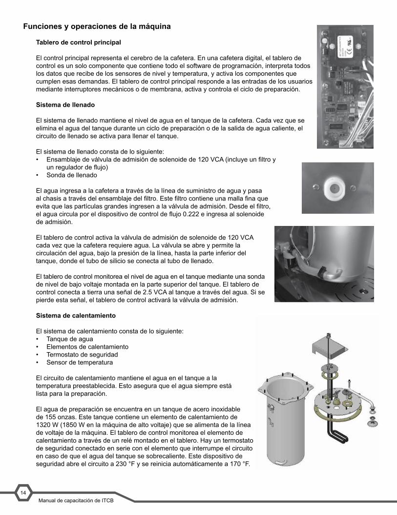
El control principal representa el cerebro de la cafetera. En una cafetera digital, el tablero de control es un solo componente que contiene todo el software de programación, interpreta todos los datos que recibe de los sensores de nivel y temperatura, y activa los componentes que cumplen esas demandas. El tablero de control principal responde a las entradas de los usuarios mediante interruptores mecánicos o de membrana, activa y controla el ciclo de preparación.
Sistema de llenado
El sistema de llenado mantiene el nivel de agua en el tanque de la cafetera. Cada vez que se elimina el agua del tanque durante un ciclo de preparación o de la salida de agua caliente, el circuito de llenado se activa para llenar el tanque.
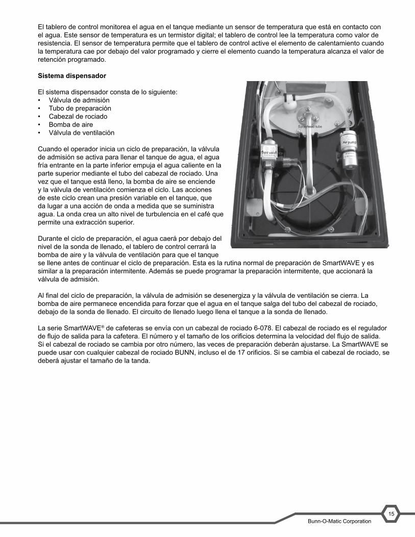
El sistema de llenado consta de lo siguiente:• Ensamblaje de válvula de admisión de solenoide de 120 VCA (incluye un filtro y
un regulador de flujo)• Sonda de llenado
El agua ingresa a la cafetera a través de la línea de suministro de agua y pasa al chasis a través del ensamblaje del filtro. Este filtro contiene una malla fina que evita que las partículas grandes ingresen a la válvula de admisión. Desde el filtro, el agua circula por el dispositivo de control de flujo 0.222 e ingresa al solenoide de admisión.
El tablero de control activa la válvula de admisión de solenoide de 120 VCA cada vez que la cafetera requiere agua. La válvula se abre y permite la circulación del agua, bajo la presión de la línea, hasta la parte inferior del tanque, donde el tubo de silicio se conecta al tubo de llenado.
El tablero de control monitorea el nivel de agua en el tanque mediante una sonda de nivel de bajo voltaje montada en la parte superior del tanque. El tablero de control conecta a tierra una señal de 2.5 VCA al tanque a través del agua. Si se pierde esta señal, el tablero de control activará la válvula de admisión.
Sistema de calentamiento
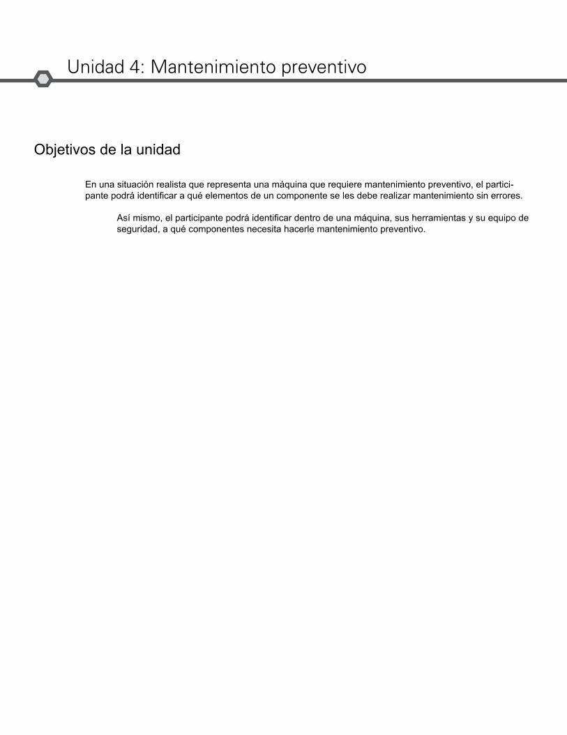
El sistema de calentamiento consta de lo siguiente:• Tanque de agua• Elementos de calentamiento• Termostato de seguridad• Sensor de temperatura
El circuito de calentamiento mantiene el agua en el tanque a la temperatura preestablecida. Esto asegura que el agua siempre está lista para la preparación.
El agua de preparación se encuentra en un tanque de acero inoxidable de 155 onzas. Este tanque contiene un elemento de calentamiento de 1320 W (1850 W en la máquina de alto voltaje) que se alimenta de la línea de voltaje de la máquina. El tablero de control monitorea el elemento de calentamiento a través de un relé montado en el tablero. Hay un termostato de seguridad conectado en serie con el elemento que interrumpe el circuito en caso de que el agua del tanque se sobrecaliente. Este dispositivo de seguridad abre el circuito a 230 °F y se reinicia automáticamente a 170 °F.
Bunn-O-Matic Corporation13
Machine Function and Operations
Main Control Board
The main control is the brain of the brewer. In a digital brewer, the control board is the single component that contains all of the programming software, it interprets all the data it receives from the level and temperature sensors and activates components to fulfill those demands. The main control board responds to the users input through the membrane switch or mechan-ical switches and activates and controls the brew cycle.
Filling System
The fill system maintains the level of water in the brewer’s tank. Anytime water is drawn off of the tank during a brew cycle or from the hot water outlet, the fill circuit activates to refill the tank.
The fill system consists of:• 120VAC solenoid inlet valve assembly (includes the strainer and flow regulator • Fill probe
Water enters the brewer through the water supply line and enters the chassis through a strainer assembly; this strainer contains a fine mesh screen to keep any large particles from entering the inlet valve. From the strainer the water flows through the 0.222 flow control device and into the inlet solenoid.
The 120VAC solenoid inlet valve is activated by the control board anytime the brewer calls for water. The valve opens and allows water to flow, under line pressure, to the bottom of the tank where the silicon tube connects to the fill tube.
The control board monitors the level of water in the tank through a low voltage level probe mounted to the top of the tank. The control board grounds a 2.5VAC signal to the tank through the water. If it looses this signal, the control board will activate the inlet valve.
Heating System
The heating system consists of: • Water tank• Heating elements• High-limit thermostat• Temperature sensor
The heating circuit maintains the water in the tank at a preset temper-ature this ensures that the water is always ready for brewing.
Water for brewing is contained in a 155 oz. stainless steel tank. This tank contains a 1320W heating element (1850W in the high voltage machine) that is powered by the line voltage into the machine. The heating element is controlled by the control board through a relay mounted on the board. There is a limit thermostat wired in series with the element that will interrupt the circuit if the water in the tank over-heats. This limit will open the circuit at 230°F and automatically resets at 170°F.
The control board monitors the water in the tank by a temperature sensor that is in contact with the water. This temperature sensor is a digital thermistor; the control board reads the temperature as value of resistance. The temperature sensor allows the control board to activate the heating element when the temperature drops below its programmed value and shut down the element when the water temperature reaches the programmed holding value.
Bunn-O-Matic Corporation13
Machine Function and Operations
Main Control Board
The main control is the brain of the brewer. In a digital brewer, the control board is the single component that contains all of the programming software, it interprets all the data it receives from the level and temperature sensors and activates components to fulfill those demands. The main control board responds to the users input through the membrane switch or mechan-ical switches and activates and controls the brew cycle.
Filling System
The fill system maintains the level of water in the brewer’s tank. Anytime water is drawn off of the tank during a brew cycle or from the hot water outlet, the fill circuit activates to refill the tank.
The fill system consists of:• 120VAC solenoid inlet valve assembly (includes the strainer and flow regulator • Fill probe
Water enters the brewer through the water supply line and enters the chassis through a strainer assembly; this strainer contains a fine mesh screen to keep any large particles from entering the inlet valve. From the strainer the water flows through the 0.222 flow control device and into the inlet solenoid.
The 120VAC solenoid inlet valve is activated by the control board anytime the brewer calls for water. The valve opens and allows water to flow, under line pressure, to the bottom of the tank where the silicon tube connects to the fill tube.
The control board monitors the level of water in the tank through a low voltage level probe mounted to the top of the tank. The control board grounds a 2.5VAC signal to the tank through the water. If it looses this signal, the control board will activate the inlet valve.
Heating System
The heating system consists of: • Water tank• Heating elements• High-limit thermostat• Temperature sensor
The heating circuit maintains the water in the tank at a preset temper-ature this ensures that the water is always ready for brewing.
Water for brewing is contained in a 155 oz. stainless steel tank. This tank contains a 1320W heating element (1850W in the high voltage machine) that is powered by the line voltage into the machine. The heating element is controlled by the control board through a relay mounted on the board. There is a limit thermostat wired in series with the element that will interrupt the circuit if the water in the tank over-heats. This limit will open the circuit at 230°F and automatically resets at 170°F.
The control board monitors the water in the tank by a temperature sensor that is in contact with the water. This temperature sensor is a digital thermistor; the control board reads the temperature as value of resistance. The temperature sensor allows the control board to activate the heating element when the temperature drops below its programmed value and shut down the element when the water temperature reaches the programmed holding value.Bunn-O-Matic Corporation
13
Machine Function and Operations
Main Control Board
The main control is the brain of the brewer. In a digital brewer, the control board is the single component that contains all of the programming software, it interprets all the data it receives from the level and temperature sensors and activates components to fulfill those demands. The main control board responds to the users input through the membrane switch or mechan-ical switches and activates and controls the brew cycle.
Filling System
The fill system maintains the level of water in the brewer’s tank. Anytime water is drawn off of the tank during a brew cycle or from the hot water outlet, the fill circuit activates to refill the tank.
The fill system consists of:• 120VAC solenoid inlet valve assembly (includes the strainer and flow regulator • Fill probe
Water enters the brewer through the water supply line and enters the chassis through a strainer assembly; this strainer contains a fine mesh screen to keep any large particles from entering the inlet valve. From the strainer the water flows through the 0.222 flow control device and into the inlet solenoid.
The 120VAC solenoid inlet valve is activated by the control board anytime the brewer calls for water. The valve opens and allows water to flow, under line pressure, to the bottom of the tank where the silicon tube connects to the fill tube.
The control board monitors the level of water in the tank through a low voltage level probe mounted to the top of the tank. The control board grounds a 2.5VAC signal to the tank through the water. If it looses this signal, the control board will activate the inlet valve.
Heating System
The heating system consists of: • Water tank• Heating elements• High-limit thermostat• Temperature sensor
The heating circuit maintains the water in the tank at a preset temper-ature this ensures that the water is always ready for brewing.
Water for brewing is contained in a 155 oz. stainless steel tank. This tank contains a 1320W heating element (1850W in the high voltage machine) that is powered by the line voltage into the machine. The heating element is controlled by the control board through a relay mounted on the board. There is a limit thermostat wired in series with the element that will interrupt the circuit if the water in the tank over-heats. This limit will open the circuit at 230°F and automatically resets at 170°F.
The control board monitors the water in the tank by a temperature sensor that is in contact with the water. This temperature sensor is a digital thermistor; the control board reads the temperature as value of resistance. The temperature sensor allows the control board to activate the heating element when the temperature drops below its programmed value and shut down the element when the water temperature reaches the programmed holding value.
Bunn-O-Matic Corporation15
El tablero de control monitorea el agua en el tanque mediante un sensor de temperatura que está en contacto con el agua. Este sensor de temperatura es un termistor digital; el tablero de control lee la temperatura como valor de resistencia. El sensor de temperatura permite que el tablero de control active el elemento de calentamiento cuando la temperatura cae por debajo del valor programado y cierre el elemento cuando la temperatura alcanza el valor de retención programado.
Sistema dispensador
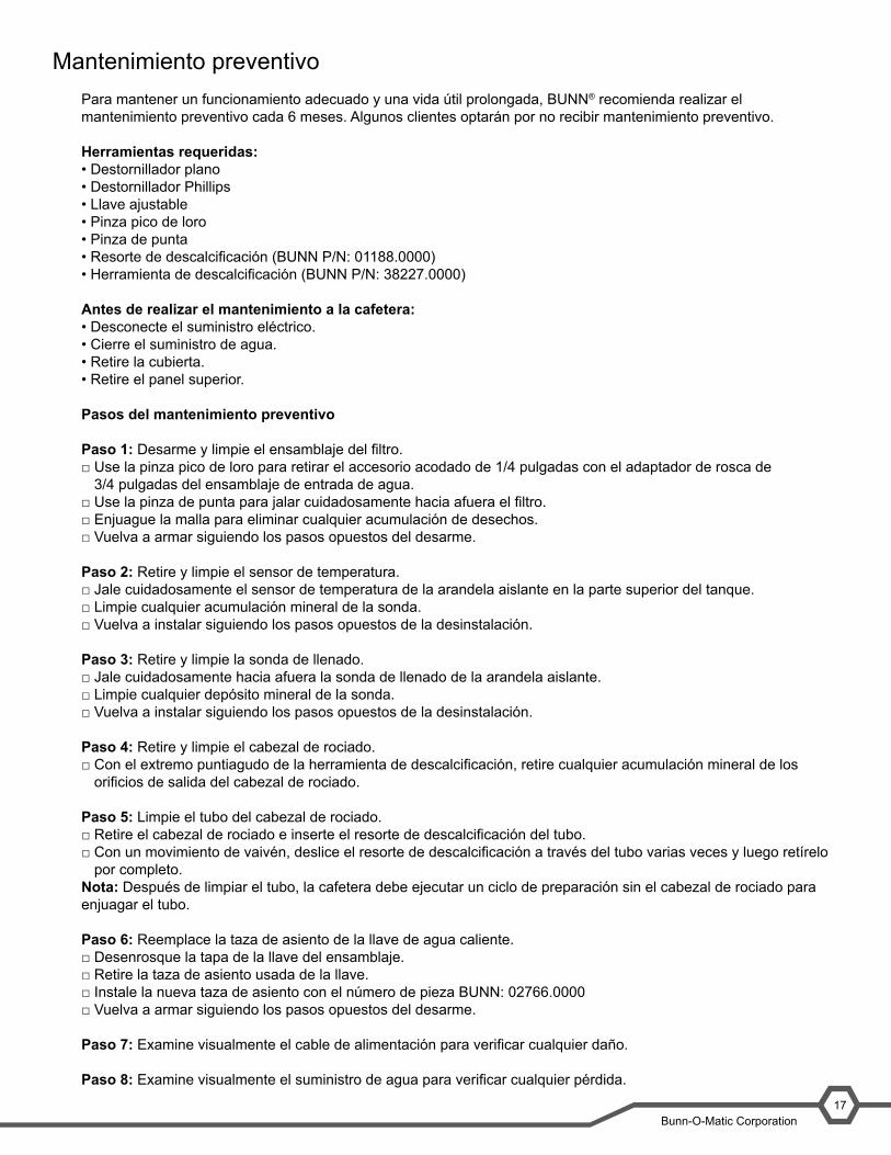
El sistema dispensador consta de lo siguiente:• Válvula de admisión• Tubo de preparación• Cabezal de rociado• Bomba de aire• Válvula de ventilación
Cuando el operador inicia un ciclo de preparación, la válvula de admisión se activa para llenar el tanque de agua, el agua fría entrante en la parte inferior empuja el agua caliente en la parte superior mediante el tubo del cabezal de rociado. Una vez que el tanque está lleno, la bomba de aire se enciende y la válvula de ventilación comienza el ciclo. Las acciones de este ciclo crean una presión variable en el tanque, que da lugar a una acción de onda a medida que se suministra agua. La onda crea un alto nivel de turbulencia en el café que permite una extracción superior.
Durante el ciclo de preparación, el agua caerá por debajo del nivel de la sonda de llenado, el tablero de control cerrará la bomba de aire y la válvula de ventilación para que el tanque se llene antes de continuar el ciclo de preparación. Esta es la rutina normal de preparación de SmartWAVE y es similar a la preparación intermitente. Además se puede programar la preparación intermitente, que accionará la válvula de admisión.
Al final del ciclo de preparación, la válvula de admisión se desenergiza y la válvula de ventilación se cierra. La bomba de aire permanece encendida para forzar que el agua en el tanque salga del tubo del cabezal de rociado, debajo de la sonda de llenado. El circuito de llenado luego llena el tanque a la sonda de llenado.
La serie SmartWAVE® de cafeteras se envía con un cabezal de rociado 6-078. El cabezal de rociado es el regulador de flujo de salida para la cafetera. El número y el tamaño de los orificios determina la velocidad del flujo de salida. Si el cabezal de rociado se cambia por otro número, las veces de preparación deberán ajustarse. La SmartWAVE se puede usar con cualquier cabezal de rociado BUNN, incluso el de 17 orificios. Si se cambia el cabezal de rociado, se deberá ajustar el tamaño de la tanda.
SmartWAVE® Training Manual14
Dispensing System
The dispensing system consists of:• Inlet valve• Brew tube• Sprayhead• Air pump• Vent valve
When the operator initiates a brew cycle the inlet valve ac-tivates to fill the water tank, the cold incoming water in the bottom pushes the hot water on the top through the spray-head tube. Once the tank is full the air pump turns on and the vent valve begins to cycle, this cycle actions creates varying pressure in the tank creating a wave action as the water is dispensed. The wave creates a high level of turbulence in the coffee leading to superior extraction.
During the brew cycle the water will drop below the level of the fill probe, the control board will shut off the air pump and vent valve to allow the tank to refill before continuing the brew cycle. This is the normal brewing routine of the SmartWAVE and is similiar to a pulse brew. Additional pulse brewing, that cycles the inlet valve, can be programmed.
At the end of the brew cycle the inlet valve is deenergized and the vent valve closes. The air pump remains on to force the water in the tank out of the sprayhead tube below the fill probe. The refill circuit then fills the tank to the fill probe.
The SmartWAVE® series of brewers are shipped with a 6-078 sprayhead. The sprayhead is the output flow regulator for the brewer. The number and size of holes determines the output flow rate. If the sprayhead is changed to a differ-ent number the brew times will have to be adjusted. The SmartWAVE can use any BUNN sprayhead, including the 17 hole, A change of sprayhead will require adjusting the batch size.
Objetivos de la unidad
Unidad 4: Mantenimiento preventivo
En una situación realista que representa una máquina que requiere mantenimiento preventivo, el partici-pante podrá identificar a qué elementos de un componente se les debe realizar mantenimiento sin errores.
Así mismo, el participante podrá identificar dentro de una máquina, sus herramientas y su equipo de seguridad, a qué componentes necesita hacerle mantenimiento preventivo.
Bunn-O-Matic Corporation17
Mantenimiento preventivoPara mantener un funcionamiento adecuado y una vida útil prolongada, BUNN® recomienda realizar el mantenimiento preventivo cada 6 meses. Algunos clientes optarán por no recibir mantenimiento preventivo.
Herramientas requeridas:• Destornillador plano• Destornillador Phillips• Llave ajustable• Pinza pico de loro• Pinza de punta• Resorte de descalcificación (BUNN P/N: 01188.0000)• Herramienta de descalcificación (BUNN P/N: 38227.0000)
Antes de realizar el mantenimiento a la cafetera:• Desconecte el suministro eléctrico.• Cierre el suministro de agua.• Retire la cubierta.• Retire el panel superior.
Pasos del mantenimiento preventivo
Paso 1: Desarme y limpie el ensamblaje del filtro.□ Use la pinza pico de loro para retirar el accesorio acodado de 1/4 pulgadas con el adaptador de rosca de
3/4 pulgadas del ensamblaje de entrada de agua.□ Use la pinza de punta para jalar cuidadosamente hacia afuera el filtro.□ Enjuague la malla para eliminar cualquier acumulación de desechos.□ Vuelva a armar siguiendo los pasos opuestos del desarme.
Paso 2: Retire y limpie el sensor de temperatura.□ Jale cuidadosamente el sensor de temperatura de la arandela aislante en la parte superior del tanque.□ Limpie cualquier acumulación mineral de la sonda.□ Vuelva a instalar siguiendo los pasos opuestos de la desinstalación.
Paso 3: Retire y limpie la sonda de llenado.□ Jale cuidadosamente hacia afuera la sonda de llenado de la arandela aislante.□ Limpie cualquier depósito mineral de la sonda.□ Vuelva a instalar siguiendo los pasos opuestos de la desinstalación.
Paso 4: Retire y limpie el cabezal de rociado.□ Con el extremo puntiagudo de la herramienta de descalcificación, retire cualquier acumulación mineral de los
orificios de salida del cabezal de rociado.
Paso 5: Limpie el tubo del cabezal de rociado.□ Retire el cabezal de rociado e inserte el resorte de descalcificación del tubo.□ Con un movimiento de vaivén, deslice el resorte de descalcificación a través del tubo varias veces y luego retírelo
por completo.Nota: Después de limpiar el tubo, la cafetera debe ejecutar un ciclo de preparación sin el cabezal de rociado para enjuagar el tubo.
Paso 6: Reemplace la taza de asiento de la llave de agua caliente.□ Desenrosque la tapa de la llave del ensamblaje.□ Retire la taza de asiento usada de la llave.□ Instale la nueva taza de asiento con el número de pieza BUNN: 02766.0000□ Vuelva a armar siguiendo los pasos opuestos del desarme.
Paso 7: Examine visualmente el cable de alimentación para verificar cualquier daño.
Paso 8: Examine visualmente el suministro de agua para verificar cualquier pérdida.

Objetivos de la unidad
Unidad 5: Resolución de problemas
En un escenario realista representado por una máquina rota, el alumno será capaz de resolver problemas, diagnosticar y reparar eficazmente el problema al hacer que la máquina vuelva a funcionar normalmente.
Con una máquina que muestra un mensaje de error y todas las herramientas y el equipo de seguridad necesarios, el alumno será capaz de diagnosticar el problema.
Con una lista de mensajes de error y problemas, el alumno podrá identificar la causa probable del mensaje o problema.
En una cafetera con un componente defectuoso, el alumno será capaz de probar el componente para determinar la causa del defecto.
Bunn-O-Matic Corporation19
Resolución de problemas y reparación
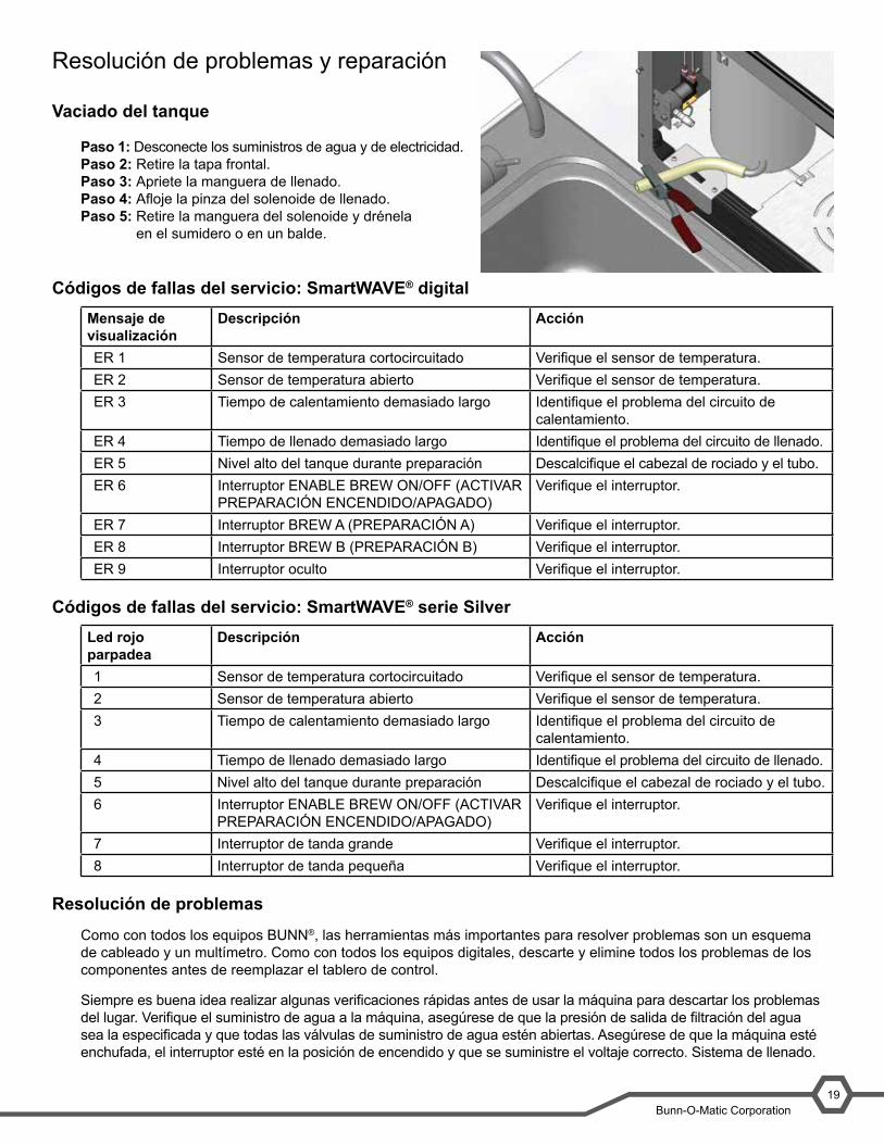
Vaciado del tanque
Paso 1: Desconecte los suministros de agua y de electricidad.Paso 2: Retire la tapa frontal.Paso 3: Apriete la manguera de llenado.Paso 4: Afloje la pinza del solenoide de llenado.Paso 5: Retire la manguera del solenoide y drénela
en el sumidero o en un balde.
Códigos de fallas del servicio: SmartWAVE® digitalMensaje de visualización
Descripción Acción
ER 1 Sensor de temperatura cortocircuitado Verifique el sensor de temperatura.ER 2 Sensor de temperatura abierto Verifique el sensor de temperatura.ER 3 Tiempo de calentamiento demasiado largo Identifique el problema del circuito de
calentamiento.ER 4 Tiempo de llenado demasiado largo Identifique el problema del circuito de llenado.ER 5 Nivel alto del tanque durante preparación Descalcifique el cabezal de rociado y el tubo.ER 6 Interruptor ENABLE BREW ON/OFF (ACTIVAR
PREPARACIÓN ENCENDIDO/APAGADO)Verifique el interruptor.
ER 7 Interruptor BREW A (PREPARACIÓN A) Verifique el interruptor.ER 8 Interruptor BREW B (PREPARACIÓN B) Verifique el interruptor.ER 9 Interruptor oculto Verifique el interruptor.
Códigos de fallas del servicio: SmartWAVE® serie SilverLed rojo parpadea
Descripción Acción
1 Sensor de temperatura cortocircuitado Verifique el sensor de temperatura.2 Sensor de temperatura abierto Verifique el sensor de temperatura.3 Tiempo de calentamiento demasiado largo Identifique el problema del circuito de
calentamiento.4 Tiempo de llenado demasiado largo Identifique el problema del circuito de llenado.5 Nivel alto del tanque durante preparación Descalcifique el cabezal de rociado y el tubo.6 Interruptor ENABLE BREW ON/OFF (ACTIVAR
PREPARACIÓN ENCENDIDO/APAGADO)Verifique el interruptor.
7 Interruptor de tanda grande Verifique el interruptor.8 Interruptor de tanda pequeña Verifique el interruptor.
Resolución de problemas
Como con todos los equipos BUNN®, las herramientas más importantes para resolver problemas son un esquema de cableado y un multímetro. Como con todos los equipos digitales, descarte y elimine todos los problemas de los componentes antes de reemplazar el tablero de control.
Siempre es buena idea realizar algunas verificaciones rápidas antes de usar la máquina para descartar los problemas del lugar. Verifique el suministro de agua a la máquina, asegúrese de que la presión de salida de filtración del agua sea la especificada y que todas las válvulas de suministro de agua estén abiertas. Asegúrese de que la máquina esté enchufada, el interruptor esté en la posición de encendido y que se suministre el voltaje correcto. Sistema de llenado.
SmartWAVE® Training Manual18
Troubleshooting and Repair
Draining the Tank
Step 1: Disconnect the water and electrical supplies.Step 2: Remove the front cover.Step 3: Pinch off the fill hose.Step 4: Loosen the clamp from the fill solenoid.Step 5: Remove the hose from the solenoid and drain into a sink or bucket.
Service Fault Codes- Digital SmartWAVE®
Display Message Description ActionER 1 Temperature sensor shorted Check the temperature sensorER 2 Temperature sensor open Check the temperature sensorER 3 Heating time too long Troubleshoot heating circuitER 4 Refill time to long Troubleshoot refill circuitER 5 High tank level- during brew Delime sprayhead and tubeER 6 Enable Brew On/Off switch Check switchER 7 Brew A switch Check switchER 8 Brew B switch Check switchER 9 Hidden switch Check switch
Service Fault Codes- SmartWAVE® Silver Series
Red LED Flashes Description Action1 Temperature sensor shorted Check the temperature sensor2 Temperature sensor open Check the temperature sensor3 Heating time too long Troubleshoot heating circuit4 Refill time to long Troubleshoot refill circuit5 High tank level- during brew Delime sprayhead and tube6 Enable Brew On/Off switch Check switch7 Large batch switch Check switch8 Small batch switch Check switch
Troubleshooting
Like all BUNN® equipment the most important tools required for troubleshooting are the wiring schematic and a multi-meter. As with all digital equipment eliminate all component issues prior to replacing the control board.
It is always a good idea to do some quick checks prior to working on the machine to eliminate site issues. Check water supply to the machine, make sure the water filtration output pressure is within specification and ensure all of the water supply valves are open. Check to make sure the machine is plugged in, the breaker is turned on, and that correct voltage is being supplied.

Manual de capacitación de ITCB20
Sistema de llenado
La cafetera no se llena
Verifique el suministro de agua a la cafetera. Asegúrese de que las válvulas estén funcionando, el filtro de agua no esté obstruido y que la línea de suministro no esté bloqueada de alguna manera. Retire la línea de suministro de la entrada de agua y drene el agua en un balde o el sumidero para verificar el suministro de agua.
Una vez que haya retirado la línea de suministro de agua, retire el adaptador y saque la malla del filtro. Observe si hay acumulación en la malla del filtro y el dispositivo de control de flujo.
Durante el proceso de llenado, la válvula de admisión de solenoide recibe aproximadamente 120 VCA del tablero de control; verifique el voltaje en la válvula. Retire los cables de la válvula y mida la resistencia de la bobina de la válvula, debe indicar aproximadamente 1400 ohmios.
Llenado excesivo de la cafetera
Retire la sonda de llenado y verifique si hay acumulación de óxido en la sonda de llenado. Limpie o reemplace la sonda.
Drene el tanque y desconecte el suministro eléctrico. Si el agua fluye en el tanque con el circuito de llenado desactivado, habrá pérdida de agua pasando el solenoide de entrada y la válvula deberá reemplazarse.
Sistema de calentamiento
La cafetera no calienta.
Durante el ciclo de calentamiento, el elemento de calentamiento funcionará aproximadamente a 11 A. Use una pinza amperimétrica para verificar el amperaje en L1.
Durante el ciclo de calentamiento, el tablero de control suministrará aproximadamente 120 VCA al elemento. Colóquela sobre las sondas del multímetro, en el lado neutro del elemento de calentamiento (se puede usar una sonda de mordazas para simplificar este proceso). Con el otro extremo de la sonda, verifique el voltaje en el lado de L1 del elemento, ambos lados del dispositivo de seguridad y en el tablero de control en el conector marcado como Heater (Calentador).
Bunn-O-Matic Corporation19
Filling System
Brewer Not Filling
Check the water supply to the brewer. Ensure that all valves are on, the water filter is not clogged, and that the supply line is not restricted in anyway. Re-move the supply line from the water inlet and open the water supply into a bucket or sink to check water supply
With the water supply line removed, remove the adapter fitting and pull out the strainer screen, check for build-up in the strainer screen and the flow control device.
During the fill process, the inlet solenoid valve receives approximately 120VAC from the control board, check voltage at the valve. Remove the wires from the valve and measure the resistance of the valve coil, it should read approxi-mately 1400ohms.
Brewer Overfilling
Remove the fill probe and check for scale build-up on the fill probe. Clean or replace the probe.
Drain the tank and disconnect the electrical supply. If water is flowing into the tank with the fill circuit deactivated water is leaking past the inlet solenoid and the valve will need to be replaced.
Heating System
Brewer Not Heating
During the heating cycle the heating element will draw approximately 11amps. Use an amp clamp to check amper-age on L1.
During the heating cycle the control board will supply approximately 120VAC to the element. Place on of the multimeter’s probes onto the neutral side of the heating element (the use of a clip-on style probe will simplify this pro-cess). Using the other end of the probe, check for voltage on the L1 side of the element, both sides of the high-limit and on the control board at the con-nector marked Heater.

Bunn-O-Matic Corporation21
Verifique la continuidad mediante el termostato de seguridad.
Verifique la resistencia del elemento de calentamiento. Debe indicar aproximadamente 10 u 11 ohmios.
Sistema dispensador
No prepara
Durante el proceso de preparación, la válvula de admisión de solenoide recibe aproximadamente 120 VCA del tablero de control; verifique el voltaje en la válvula. Retire los cables de la válvula y mida la resistencia de la bobina de la válvula, debe indicar aproximadamente 1400 ohmios.
Sin ondas
Verifique la válvula de ventilación y la bomba de aire, ambos componentes reciben 12 VCC del tablero de control.
Verifique el tubo del cabezal de rociado en busca de acumulación de óxido.
Mapa de componentes de conmutación
1. TH1 = Calentador2. Q2 = Bomba de aire3. Q4 = Válvula de ventilación4. Q8 = Válvula de admisión
SmartWAVE® Training Manual20
Check for continuity through the high-limit thermostat.
Check the resistance of the heating element. It should read approximately 10-11 ohms.
Dispensing System
Not Brewing
During the brew process, the inlet solenoid valve receives approximately 120VAC from the control board, check voltage at the valve. Remove the wires from the valve and measure the resistance of the valve coil, it should read ap-proximately 1400ohms.
No Wave
Check the vent valve and air pump both components receive 12VDC from the control board.
Brew Basket Overflowing
Check the sprayhead tube and sprayhead for scale build-up.
Switching Component Map
1. TH1 = Heater2. Q2 = Air Pump3. Q4 = Vent Valve4. Q8 = Inlet Valve 1
2
3 4