egiaudio.comegiaudio.com/wp-content/uploads/2015/05/Escenic_63001_63002.pdf · a sonorizar. Le...
18
Transcript of egiaudio.comegiaudio.com/wp-content/uploads/2015/05/Escenic_63001_63002.pdf · a sonorizar. Le...

3
Introducción
Estimado instalador: En primer lugar, le agradecemos que haya elegido nuestros productos y le deseamos que la instalación funcione perfectamente y "a laprimera". Para ello le rogamos siga cuidadosamente las instrucciones que le ofrecemos en este Manual.Todos los elementos que constituyen la serie "Escenic" tienen como uso natural la instalación de sonorización en locales de ocio y también el refuerzo sonoro,musical y/o hablado, en pequeños salones de actos, etc.Es importante tener en cuenta que se puede encontrar con limitaciones de uso de los equipos debido bien a ordenanzas municipales, bien a legislaciónsubsidiaria autonómica relativas a actividades molestas (ruido) o incluso por aplicación de riesgos laborales de las personas que trabajan en dichos locales.De igual forma hay que tener en cuenta que, como con cualquier otro tipo de instalación de sonorización, para obtener un resultado satisfactorio nosolo consiste en saber elegir el material electroacústico adecuado a las necesidades sino también tener en cuenta las condiciones acústicas del espacioa sonorizar. Le recomendamos, por tanto, que consulte con empresas especializadas en tratamiento de acondicionamiento acústico si tiene alguna dudao necesita asesoramiento.
Introduction
Dear installer: First of all, we would like to thank you for choosing EGi products. We wish you that the installation works perfectly fromthe very beginning. In order to achieve it, please, follow carefully the instructions that we offer you in this manual.All of the elements that make up the "ESCENIC" series are for the installation of sound systems on leisure premises and also to reinforcethe sound, music and /or speak systems in small assembly halls, etc.It is important to bear in mind that local regulations, regional subsidiary legislation on activities that generate noise or even the applicationof regulations concerning work risks to people working on these premises may establish limits on the use of the equipment.In any case, it must be taken into account that, as with any other type of sound installation, to obtain a satisfactory result it is nota question of just choosing the right electro-acoustic material according to needs but that it is also essential to bear in mind theacoustic conditions of the space in which the sound system is to be installed. We would thus recommend consulting companiesspecialised in dealing with acoustic conditioning if you have any doubts or require any advice.
CAUTIONRISK OF ELECTRIC SHOCK
DO NOT OPEN
DO NOT EXPOSE TORAIN OR MOISTURE!
ATTENTIONDANGER D'ELECTROCUTION
NE PAS OUVRIR
NE PAS EXPOSER Á LAPLUIE NI Á L'HUMIDITÉ!
4
CAUTIONRISK OF ELECTRIC SHOCK
DO NOT OPEN
DO NOT EXPOSE TORAIN OR MOISTURE!
ATTENTIONDANGER D'ELECTROCUTION
NE PAS OUVRIR
NE PAS EXPOSER Á LAPLUIE NI Á L'HUMIDITÉ!
Safety precautions
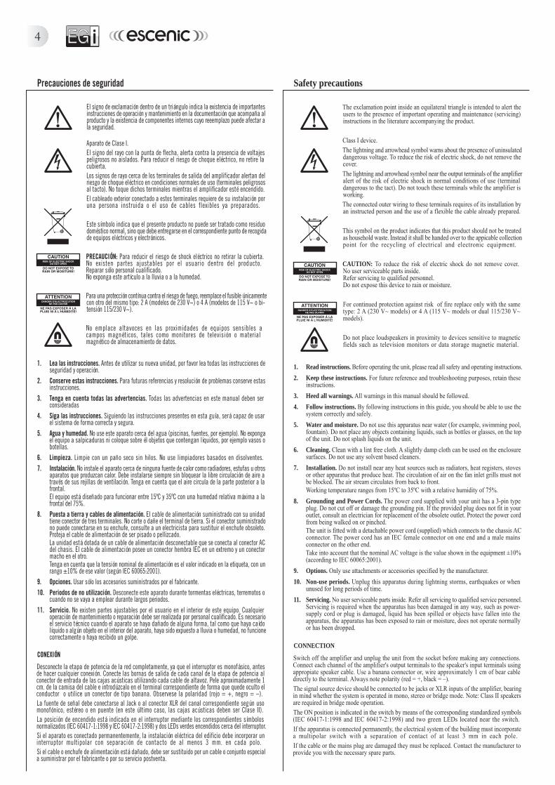
The exclamation point inside an equilateral triangle is intended to alert theusers to the presence of important operating and maintenance (servicing)instructions in the literature accompanying the product.
Class I device.The lightning and arrowhead symbol warns about the presence of uninsulateddangerous voltage. To reduce the risk of electric shock, do not remove thecover.The lightning and arrowhead symbol near the output terminals of the amplifieralert of the risk of electric shock in normal conditions of use (terminaldangerous to the tact). Do not touch these terminals while the amplifier isworking.The connected outer wiring to these terminals requires of its installation byan instructed person and the use of a flexible the cable already prepared.
This symbol on the product indicates that this product should not be treatedas household waste. Instead it shall be handed over to the appicable collectionpoint for the recycling of electrical and electronic equipment.
CAUTION: To reduce the risk of electric shock do not remove cover.No user serviceable parts inside.Refer servicing to qualified personnel.Do not expose this device to rain or moisture.
For continued protection against risk of fire replace only with the sametype: 2 A (230 V~ models) or 4 A (115 V~ models or dual 115/230 V~models).
Do not place loudspeakers in proximity to devices sensitive to magneticfields such as television monitors or data storage magnetic material.
1. Read instructions. Before operating the unit, please read all safety and operating instructions.
2. Keep these instructions. For future reference and troubleshooting purposes, retain theseinstructions.
3. Heed all warnings. All warnings in this manual should be followed.
4. Follow instructions. By following instructions in this guide, you should be able to use thesystem correctly and safely.
5. Water and moisture. Do not use this apparatus near water (for example, swimming pool,fountain). Do not place any objects containing liquids, such as bottles or glasses, on the topof the unit. Do not splash liquids on the unit.
6. Cleaning. Clean with a lint free cloth. A slightly damp cloth can be used on the enclosuresurfaces. Do not use any solvent based cleaners.
7. Installation. Do not install near any heat sources such as radiators, heat registers, stovesor other apparatus that produce heat. The circulation of air on the fan inlet grills must notbe blocked. The air stream circulates from back to front.Working temperature ranges from 15ºC to 35ºC with a relative humidity of 75%.
8. Grounding and Power Cords. The power cord supplied with your unit has a 3-pin typeplug. Do not cut off or damage the grounding pin. If the provided plug does not fit in youroutlet, consult an electrician for replacement of the obsolete outlet. Protect the power cordfrom being walked on or pinched.The unit is fitted with a detachable power cord (supplied) which connects to the chassis ACconnector. The power cord has an IEC female connector on one end and a male mainsconnector on the other end.Take into account that the nominal AC voltage is the value shown in the equipment ±10%(according to IEC 60065:2001).
9. Options. Only use attachments or accessories specified by the manufacturer.
10. Non-use periods. Unplug this apparatus during lightning storms, earthquakes or whenunused for long periods of time.
11. Servicing. No user serviceable parts inside. Refer all servicing to qualified service personnel.Servicing is required when the apparatus has been damaged in any way, such as power-supply cord or plug is damaged, liquid has been spilled or objects have fallen into theapparatus, the apparatus has been exposed to rain or moisture, does not operate normallyor has been dropped.
CONNECTION
Switch off the amplifier and unplug the unit from the socket before making any connections.Connect each channel of the amplifier's output terminals to the speaker's input terminals usingappropiate speaker cable. Use a banana connector or, wire approximately 1 cm of bear cabledirectly to the terminal. Always note polarity (red = +, black = –).The signal source device should be connected to be jacks or XLR inputs of the amplifier, bearingin mind whether the system is operated in mono, stereo or bridge mode. Note: Class II speakersare required in bridge mode operation.The ON position is indicated in the switch by means of the corresponding standardized symbols(IEC 60417-1:1998 and IEC 60417-2:1998) and two green LEDs located near the switch.If the apparatus is connected permanently, the electrical system of the building must incorporatea multipolar switch with a separation of contact of at least 3 mm in each pole.If the cable or the mains plug are damaged they must be replaced. Contact the manufacturer toprovide you with the necessary spare parts.
Precauciones de seguridad
El signo de exclamación dentro de un triángulo indica la existencia de importantesinstrucciones de operación y mantenimiento en la documentación que acompaña alproducto y la existencia de componentes internos cuyo reeemplazo puede afectar ala seguridad.
Aparato de Clase I.El signo del rayo con la punta de flecha, alerta contra la presencia de voltajespeligrosos no aislados. Para reducir el riesgo de choque eléctrico, no retire lacubierta.Los signos de rayo cerca de los terminales de salida del amplificador alertan delriesgo de choque eléctrico en condiciones normales de uso (terminales peligrososal tacto). No toque dichos terminales mientras el amplificador esté encendido.El cableado exterior conectado a estos terminales requiere de su instalación poruna persona instruida o el uso de cables flexibles ya preparados.
Este símbolo indica que el presente producto no puede ser tratado como residuodoméstico normal, sino que debe entregarse en el correspondiente punto de recogidade equipos eléctricos y electrónicos.
PRECAUCIÓN: Para reducir el riesgo de shock eléctrico no retirar la cubierta.No existen partes ajustables por el usuario dentro del producto.Reparar sólo personal cualificado.No exponga este artículo a la lluvia o a la humedad.
Para una protección contínua contra el riesgo de fuego, reemplace el fusible únicamentecon otro del mismo tipo: 2 A (modelos de 230 V~) o 4 A (modelos de 115 V~ o bi-tensión 115/230 V~).
No emplace altavoces en las proximidades de equipos sensibles acampos magnéticos, tales como monitores de televisión o materialmagnético de almacenamiento de datos.
1. Lea las instrucciones. Antes de utilizar su nueva unidad, por favor lea todas las instrucciones deseguridad y operación.
2. Conserve estas instrucciones. Para futuras referencias y resolución de problemas conserve estasinstrucciones.
3. Tenga en cuenta todas las advertencias. Todas las advertencias en este manual deben serconsideradas
4. Siga las instrucciones. Siguiendo las instrucciones presentes en esta guía, será capaz de usarel sistema de forma correcta y segura.
5. Agua y humedad. No use este aparato cerca del agua (piscinas, fuentes, por ejemplo). No expongael equipo a salpicaduras ni coloque sobre él objetos que contengan líquidos, por ejemplo vasos obotellas.
6. Limpieza. Limpie con un paño seco sin hilos. No use limpiadores basados en disolventes.7. Instalación. No instale el aparato cerca de ninguna fuente de calor como radiadores, estufas u otros
aparatos que produzcan calor. Debe instalarse siempre sin bloquear la libre circulación de aire através de sus rejillas de ventilación. Tenga en cuenta que el aire circula de la parte posterior a lafrontal.El equipo está diseñado para funcionar entre 15ºC y 35ºC con una humedad relativa máxima a lafrontal del 75%.
8. Puesta a tierra y cables de alimentación. El cable de alimentación suministrado con su unidadtiene conector de tres terminales. No corte o dañe el terminal de tierra. Si el conector suministradono puede conectarse en su enchufe, consulte a un electricista para sustituir el enchufe obsoleto.Proteja el cable de alimentación de ser pisado o pellizcado.La unidad está dotada de un cable de alimentación desconectable que se conecta al conector ACdel chasis. El cable de alimentación posee un conector hembra IEC en un extremo y un conectormacho en el otro.Tenga en cuenta que la tensión nominal de alimentación es el valor indicado en la etiqueta, con unrango ±10% de ese valor (según IEC 60065:2001).
9. Opciones. Usar sólo los accesorios suministrados por el fabricante.10. Periodos de no utilización. Desconecte este aparato durante tormentas eléctricas, terremotos o
cuando no se vaya a emplear durante largos periodos.11. Servicio. No existen partes ajustables por el usuario en el interior de este equipo. Cualquier
operación de mantenimiento o reparación debe ser realizada por personal cualificado. Es necesarioel servicio técnico cuando el aparato se haya dañado de alguna forma, tal como que haya caídolíquido o algún objeto en el interior del aparato, haya sido expuesto a lluvia o humedad, no funcionecorrectamente o haya recibido un golpe.
CONEXIÓN
Desconecte la etapa de potencia de la red completamente, ya que el interruptor es monofásico, antesde hacer cualquier conexión. Conecte las bornas de salida de cada canal de la etapa de potencia alconector de entrada de las cajas acústicas utilizando cada cable de altavoz. Pele aproximadamente 1cm. de la camisa del cable e introdúzcalo en el terminal correspondiente de forma que quede oculto elconductor o utilice un conector de tipo banana. Observese la polaridad (rojo = +, negro = –).La fuente de señal debe conectarse al Jack o al conector XLR del canal correspondiente según usomonofónico, estéreo o en puente (en este último caso, las cajas acústicas deben ser Clase II).La posición de encendido está indicada en el interruptor mediante los correspondientes símbolosnormalizados (IEC 60417-1:1998 y IEC 60417-2:1998) y dos LEDs verdes encendidos cerca del interruptor.Si el aparato es conectado permanentemente, la instalación eléctrica del edificio debe incorporar uninterruptor multipolar con separación de contacto de al menos 3 mm. en cada polo.Si el cable o enchufe de alimentación está dañado, debe ser sustituido por un cable o conjunto especiala suministrar por el fabricante o por su servicio postventa.
63001 - Etapa de potencia de 2 x 200 W; 1 x 400 W / 2 x 200 W; 1 x 400 W Power amplifier
5
Características
GENERALES• Entradas balanceadas con conector JACK de 6.3 mm y XLR (Cannon).• Evacuación de calor de alta eficacia, gracias a la ventilación forzada.• Baja distorsión y alta relación señal/ruido.• Control de volumen para cada canal.• Selector antibucles de tierra.• Selector de sensibilidad entre 0.775 V, 1 V y 1.44 V.• Modo de funcionamiento seleccionable: estéreo, paralelo o puente.• Protección de cada salida frente a carga excesiva, aumento de temperatura y corriente
continua en la salida.• Limitación anti-clip. El equipo reconoce el "clip" y lo atenúa.• Indicadores LED de recorte (clip), protección y presencia de señal de entrada.
63001• Módulo estéreo de potencia sobredimensionado de fácil reemplazo en caso de daño.• Ventilador de velocidad variable.• Detección y protección ante cortocircuitos de salida.• Salida de altavoces con bornas.• 1 unidad de rack de 19" (1U).
Features
GENERAL• Balanced 6.3 mm phone jack inputs and XLR connectors.• High efficiency heat dissipation through the use of fan cooling.• Low distortion and high signal-to-noise ratio.• Independent volume controls.• Ground anti-loop switch.• Input sensitivity switchable between 0.775 V, 1 V and 1.44 V.• Stereo, parallel or mono operation modes.• Channel protection against output overloading, overheating and DC presence.• Clip limiter. The amplifier recognizes and attenuates clipping.• Clip protection and iddle LED indicators.
63001• Oversized stereo power module facilitates servicing in the event of a breakdown.• Variable speed cooling fan.• Safeguarded against output short-circuit.• Binding posts speaker output.• One 19" rack unit (1U).
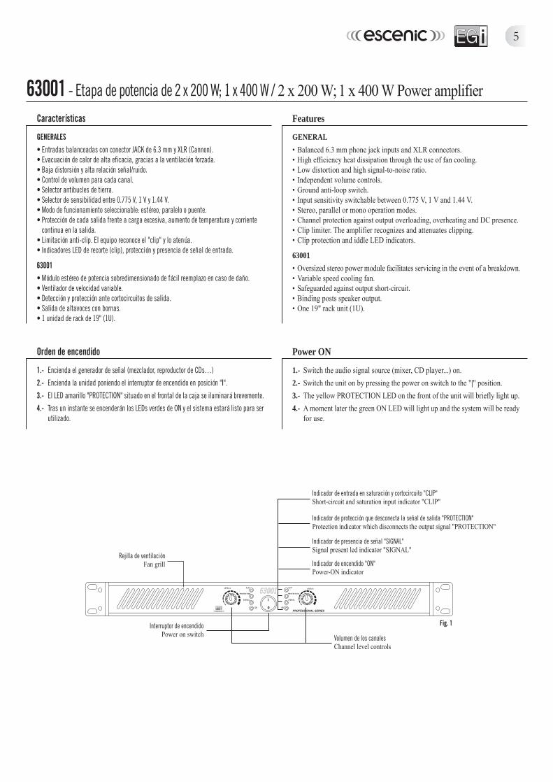
Rejilla de ventilaciónFan grill
Volumen de los canalesChannel level controls
Indicador de encendido "ON"Power-ON indicator
Indicador de presencia de señal "SIGNAL"Signal present led indicator "SIGNAL"
Indicador de entrada en saturación y cortocircuito "CLIP"Short-circuit and saturation input indicator "CLIP"
Fig. 1Interruptor de encendidoPower on switch
Indicador de protección que desconecta la señal de salida "PROTECTION"Protection indicator which disconnects the output signal "PROTECTION"
Orden de encendido
1.- Encienda el generador de señal (mezclador, reproductor de CDs…)2.- Encienda la unidad poniendo el interruptor de encendido en posición "|".3.- El LED amarillo "PROTECTION" situado en el frontal de la caja se iluminará brevemente.4.- Tras un instante se encenderán los LEDs verdes de ON y el sistema estará listo para ser
utilizado.
Power ON
1.- Switch the audio signal source (mixer, CD player...) on.2.- Switch the unit on by pressing the power on switch to the "|" position.3.- The yellow PROTECTION LED on the front of the unit will briefly light up.4.- A moment later the green ON LED will light up and the system will be ready
for use.
6
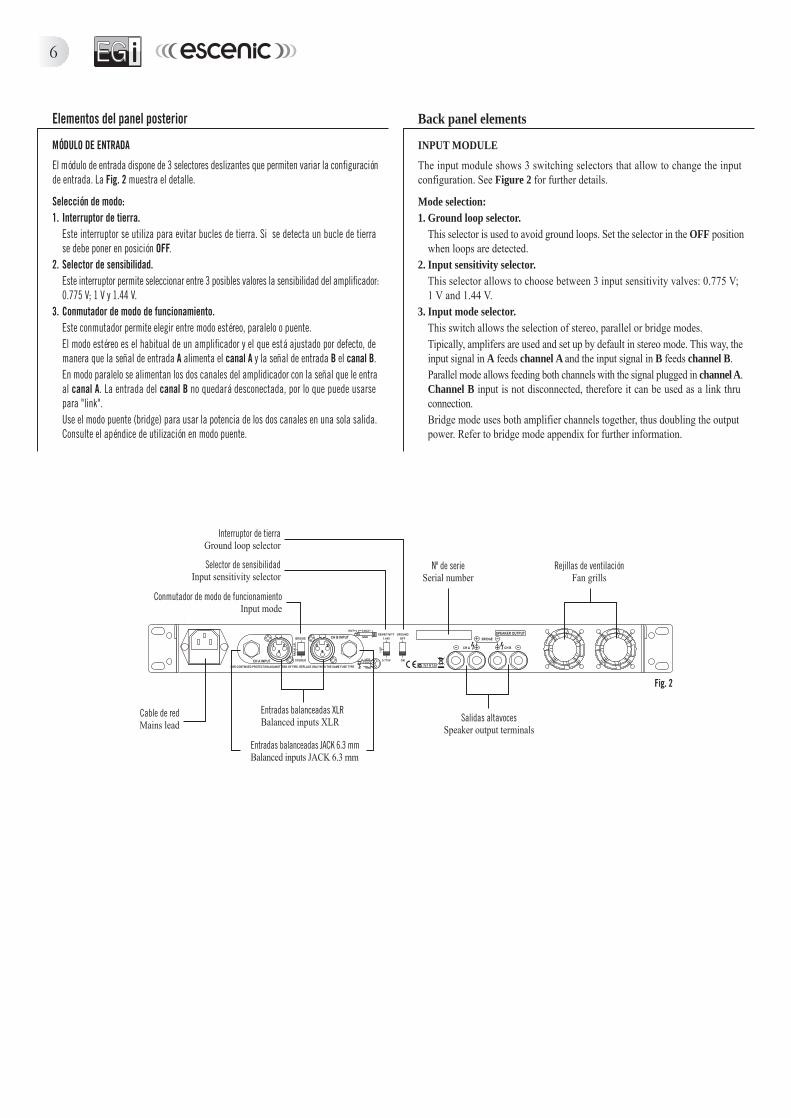
Cable de redMains lead
Rejillas de ventilaciónFan grills
Entradas balanceadas JACK 6.3 mmBalanced inputs JACK 6.3 mm
Entradas balanceadas XLRBalanced inputs XLR
Fig. 2
Nº de serieSerial number
Salidas altavocesSpeaker output terminals
Conmutador de modo de funcionamientoInput mode
Selector de sensibilidadInput sensitivity selector
Interruptor de tierraGround loop selector
Elementos del panel posterior
MÓDULO DE ENTRADA
El módulo de entrada dispone de 3 selectores deslizantes que permiten variar la configuraciónde entrada. La Fig. 2 muestra el detalle.
Selección de modo:1. Interruptor de tierra.
Este interruptor se utiliza para evitar bucles de tierra. Si se detecta un bucle de tierrase debe poner en posición OFF.
2. Selector de sensibilidad.Este interruptor permite seleccionar entre 3 posibles valores la sensibilidad del amplificador:0.775 V; 1 V y 1.44 V.
3. Conmutador de modo de funcionamiento.Este conmutador permite elegir entre modo estéreo, paralelo o puente.El modo estéreo es el habitual de un amplificador y el que está ajustado por defecto, demanera que la señal de entrada A alimenta el canal A y la señal de entrada B el canal B.En modo paralelo se alimentan los dos canales del amplidicador con la señal que le entraal canal A. La entrada del canal B no quedará desconectada, por lo que puede usarsepara "link".Use el modo puente (bridge) para usar la potencia de los dos canales en una sola salida.Consulte el apéndice de utilización en modo puente.
Back panel elements
INPUT MODULE
The input module shows 3 switching selectors that allow to change the inputconfiguration. See Figure 2 for further details.
Mode selection:1. Ground loop selector.
This selector is used to avoid ground loops. Set the selector in the OFF positionwhen loops are detected.
2. Input sensitivity selector.This selector allows to choose between 3 input sensitivity valves: 0.775 V;1 V and 1.44 V.
3. Input mode selector.This switch allows the selection of stereo, parallel or bridge modes.Tipically, amplifers are used and set up by default in stereo mode. This way, theinput signal in A feeds channel A and the input signal in B feeds channel B.Parallel mode allows feeding both channels with the signal plugged in channel A.Channel B input is not disconnected, therefore it can be used as a link thruconnection.Bridge mode uses both amplifier channels together, thus doubling the outputpower. Refer to bridge mode appendix for further information.
7
Ejemplos de conexión / Connection details
Etapa de potencia 6300163001 Power amplifier
Etapa de potencia 6300263002 Power amplifier
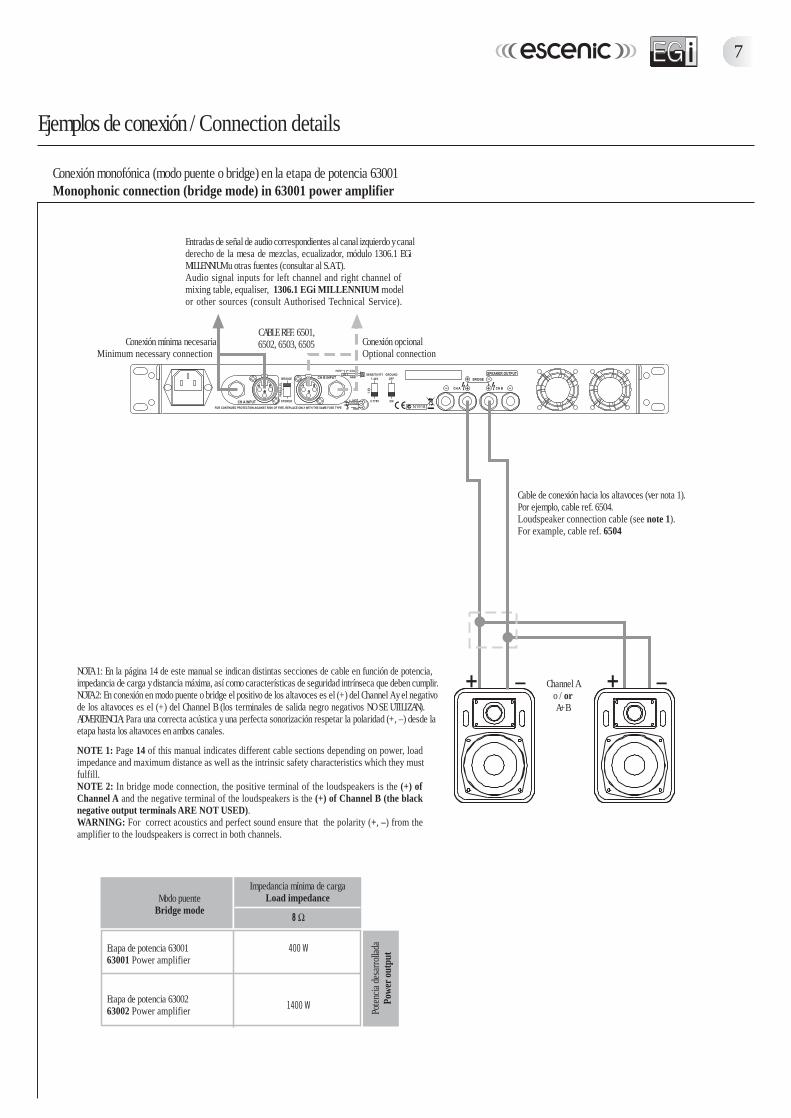
Impedancia mínima de cargaLoad impedance
Conexión monofónica (modo puente o bridge) en la etapa de potencia 63001Monophonic connection (bridge mode) in 63001 power amplifier
Channel Ao / orA+B
NOTA 1: En la página 14 de este manual se indican distintas secciones de cable en función de potencia,impedancia de carga y distancia máxima, así como características de seguridad intrínseca que deben cumplir.NOTA 2: En conexión en modo puente o bridge el positivo de los altavoces es el (+) del Channel A y el negativode los altavoces es el (+) del Channel B (los terminales de salida negro negativos NO SE UTILIZAN).ADVERTENCIA: Para una correcta acústica y una perfecta sonorización respetar la polaridad (+, –) desde laetapa hasta los altavoces en ambos canales.
NOTE 1: Page 14 of this manual indicates different cable sections depending on power, loadimpedance and maximum distance as well as the intrinsic safety characteristics which they mustfulfill.NOTE 2: In bridge mode connection, the positive terminal of the loudspeakers is the (+) ofChannel A and the negative terminal of the loudspeakers is the (+) of Channel B (the blacknegative output terminals ARE NOT USED).WARNING: For correct acoustics and perfect sound ensure that the polarity (+, –) from theamplifier to the loudspeakers is correct in both channels.
Conexión opcionalOptional connection
Conexión mínima necesariaMinimum necessary connection
Poten
cia de
sarro
llada
Powe
r out
put
CABLE REF. 6501,6502, 6503, 6505
Cable de conexión hacia los altavoces (ver nota 1).Por ejemplo, cable ref. 6504.Loudspeaker connection cable (see note 1).For example, cable ref. 6504
Entradas de señal de audio correspondientes al canal izquierdo y canalderecho de la mesa de mezclas, ecualizador, módulo 1306.1 EGiMILLENNIUM u otras fuentes (consultar al S.A.T.).Audio signal inputs for left channel and right channel ofmixing table, equaliser, 1306.1 EGi MILLENNIUM modelor other sources (consult Authorised Technical Service).
Modo puenteBridge mode
8
Ejemplos de conexión / Connection details
Etapa de potencia 6300163001 Power amplifier
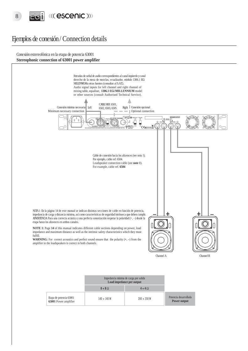
Impedancia mínima de carga por salidaLoad impedance per output
Conexión estereofónica en la etapa de potencia 63001Stereophonic connection of 63001 power amplifier
NOTA 1: En la página 14 de este manual se indican distintas secciones de cable en función de potencia,impedancia de carga y distancia máxima, así como características de seguridad intrínseca que deben cumplir.ADVERTENCIA: Para una correcta acústica y una perfecta sonorización respetar la polaridad (+, –) desde laetapa hasta los altavoces en ambos canales.
NOTE 1: Page 14 of this manual indicates different cable sections depending on power, loadimpedance and maximum distance as well as the intrinsic safety characteristics which they mustfulfill.WARNING: For correct acoustics and perfect sound ensure that the polarity (+, –) from theamplifier to the loudspeakers is correct in both channels.
Conexión opcionalOptional connection
Conexión mínima necesariaMinimum necessary connection
Potencia desarrolladaPower output
CABLE REF. 6501,6502, 6503, 6505
Cable de conexión hacia los altavoces (ver nota 1).Por ejemplo, cable ref. 6504.Loudspeaker connection cable (see note 1).For example, cable ref. 6504
Entradas de señal de audio correspondientes al canal izquierdo y canalderecho de la mesa de mezclas, ecualizador, módulo 1306.1 EGiMILLENNIUM u otras fuentes (consultar al S.A.T.).Audio signal inputs for left channel and right channel ofmixing table, equaliser, 1306.1 EGi MILLENNIUM modelor other sources (consult Authorised Technical Service).
Channel A Channel B
Left Right

63002 - Etapa de potencia de 2 x 700 W; 1 x 1400 W (línea 100V) / 2 x 700 W; 1 x 1400 W (100V line) Power amplifier
9
Rejilla de ventilaciónFan grill
Volumen de los canalesChannels level controls
Indicador de encendido "ON"Power-ON indicator
Indicador de presencia de señal "SIGNAL"Signal present led indicator "SIGNAL"
Indicador de entrada en saturación y cortocircuito "CLIP"Short-circuit and saturation input indicator "CLIP"
Fig. 3Interruptor de encendidoPower on switch
Indicador de protección que desconecta la señal de salida "PROTECTION"Protection indicator which disconnects the output signal "PROTECTION"
Características
GENERALES• Entradas balanceadas con conector JACK de 6.3 mm y XLR (Cannon).• Evacuación de calor de alta eficacia, gracias a la ventilación forzada.• Baja distorsión y alta relación señal/ruido.• Control de volumen para cada canal.• Selector antibucles de tierra.• Selector de sensibilidad entre 0.775 V, 1 V y 1.44 V.• Modo de funcionamiento seleccionable: estéreo, paralelo o puente.• Protección de cada salida frente a carga excesiva, aumento de temperatura y corriente
continua en la salida.• Limitación anti-clip. El equipo reconoce el "clip" y lo atenúa.• Indicadores LED de recorte (clip), protección y presencia de señal de entrada.
63002• Tecnología modular: cada canal está formado por un solo módulo que incluye la totalidad
de sus componentes electrónicos, fácilmente intercambiable y totalmente compacto.• Salida de altavoces con bornas y SPEAKON®.• 2 unidades de rack de 19" (2U).
Features
GENERAL• Balanced 6.3 mm phone jack inputs and XLR connectors.• High efficiency heat dissipation through the use of fan cooling.• Low distortion and high signal-to-noise ratio.• Independent volume controls.• Ground anti-loop switch.• Input sensitivity switchable between 0.775 V, 1 V and 1.44 V.• Stereo, parallel or mono operation modes.• Channel protection against output overloading, overheating and DC presence.• Clip limiter. The amplifier recognizes and attenuates clipping.• Clip protection and iddle LED indicators.
63002• Modular technology: Completely independent power modules facilitate servicing
in the event of a breakdown.• Binding post and SPEAKON® speaker outputs.• Two 19" rack units (2U).
Orden de encendido
1.- Encienda el generador de señal (mezclador, reproductor de CDs…)2.- Encienda la unidad poniendo el interruptor de encendido en posición "|".3.- El LED amarillo "PROTECTION" situado en el frontal de la caja se iluminará brevemente.4.- Tras un instante se encenderán los LEDs verdes de ON y el sistema estará listo para ser
utilizado.
Power ON
1.- Switch the audio signal source (mixer, CD player...) on.2.- Switch the unit on by pressing the power on switch to the "|" position.3.- The yellow PROTECTION LED on the front of the unit will briefly light up.4.- A moment later the green ON LED will light up and the system will be ready
for use.
10
Entradas balanceadas JACK 6.3 mmBalanced inputs JACK 6.3 mm
Entradas balanceadas XLRBalanced inputs XLR
Fig. 4
Nº de serieSerial number
Selector de sensibilidadInput sensitivity selector
Conmutador de modo de funcionamientoInput mode
Interruptor de tierraGround loop selector
Cable de redMains lead
Rejilla de ventilaciónFan grill
Rejilla de ventilaciónFan grill
Salida altavocesSpeaker output terminals
Salida altavoces SPEAKON®
SPEAKON® speaker output terminals
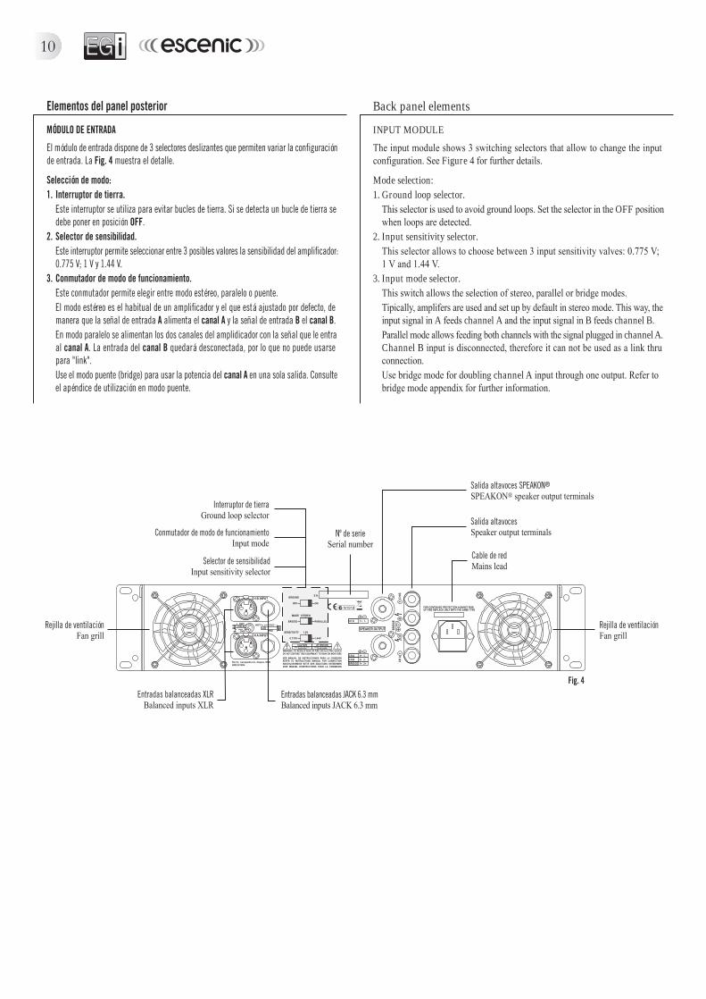
Elementos del panel posterior
MÓDULO DE ENTRADA
El módulo de entrada dispone de 3 selectores deslizantes que permiten variar la configuraciónde entrada. La Fig. 4 muestra el detalle.
Selección de modo:1. Interruptor de tierra.
Este interruptor se utiliza para evitar bucles de tierra. Si se detecta un bucle de tierra sedebe poner en posición OFF.
2. Selector de sensibilidad.Este interruptor permite seleccionar entre 3 posibles valores la sensibilidad del amplificador:0.775 V; 1 V y 1.44 V.
3. Conmutador de modo de funcionamiento.Este conmutador permite elegir entre modo estéreo, paralelo o puente.El modo estéreo es el habitual de un amplificador y el que está ajustado por defecto, demanera que la señal de entrada A alimenta el canal A y la señal de entrada B el canal B.En modo paralelo se alimentan los dos canales del amplidicador con la señal que le entraal canal A. La entrada del canal B quedará desconectada, por lo que no puede usarsepara "link".Use el modo puente (bridge) para usar la potencia del canal A en una sola salida. Consulteel apéndice de utilización en modo puente.
Back panel elements
INPUT MODULE
The input module shows 3 switching selectors that allow to change the inputconfiguration. See Figure 4 for further details.
Mode selection:1. Ground loop selector.
This selector is used to avoid ground loops. Set the selector in the OFF positionwhen loops are detected.
2. Input sensitivity selector.This selector allows to choose between 3 input sensitivity valves: 0.775 V;1 V and 1.44 V.
3. Input mode selector.This switch allows the selection of stereo, parallel or bridge modes.Tipically, amplifers are used and set up by default in stereo mode. This way, theinput signal in A feeds channel A and the input signal in B feeds channel B.Parallel mode allows feeding both channels with the signal plugged in channel A.Channel B input is disconnected, therefore it can not be used as a link thruconnection.Use bridge mode for doubling channel A input through one output. Refer tobridge mode appendix for further information.
11
Ejemplos de conexión / Connection details
Etapa de potencia 630026301 Power amplifier
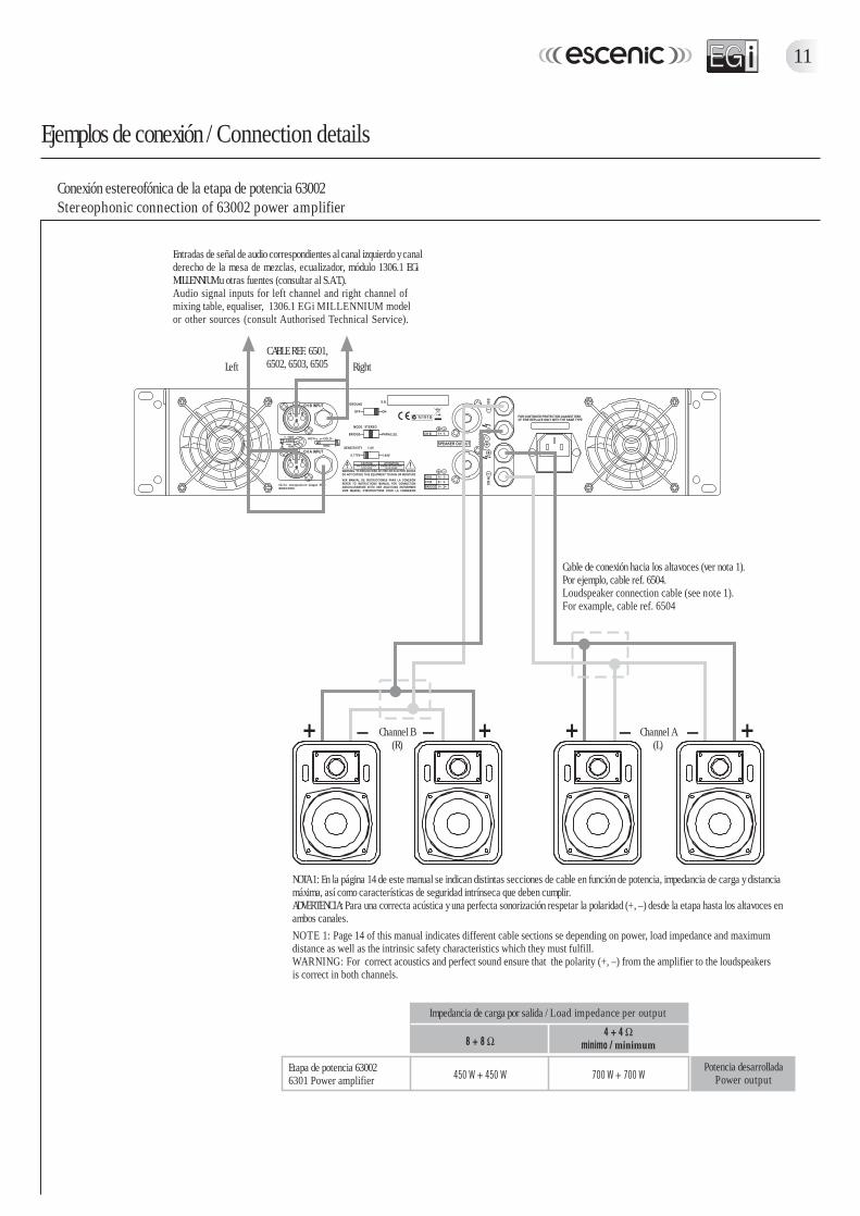
Cable de conexión hacia los altavoces (ver nota 1).Por ejemplo, cable ref. 6504.Loudspeaker connection cable (see note 1).For example, cable ref. 6504
Entradas de señal de audio correspondientes al canal izquierdo y canalderecho de la mesa de mezclas, ecualizador, módulo 1306.1 EGiMILLENNIUM u otras fuentes (consultar al S.A.T.).Audio signal inputs for left channel and right channel ofmixing table, equaliser, 1306.1 EGi MILLENNIUM modelor other sources (consult Authorised Technical Service).
NOTA 1: En la página 14 de este manual se indican distintas secciones de cable en función de potencia, impedancia de carga y distanciamáxima, así como características de seguridad intrínseca que deben cumplir.ADVERTENCIA: Para una correcta acústica y una perfecta sonorización respetar la polaridad (+, –) desde la etapa hasta los altavoces enambos canales.NOTE 1: Page 14 of this manual indicates different cable sections se depending on power, load impedance and maximumdistance as well as the intrinsic safety characteristics which they must fulfill.WARNING: For correct acoustics and perfect sound ensure that the polarity (+, –) from the amplifier to the loudspeakersis correct in both channels.
Impedancia de carga por salida / Load impedance per output
Conexión estereofónica de la etapa de potencia 63002Stereophonic connection of 63002 power amplifier
Channel B(R)
Channel A(L)
Potencia desarrolladaPower output
CABLE REF. 6501,6502, 6503, 6505Left Right
12
Ejemplos de conexión / Connection details
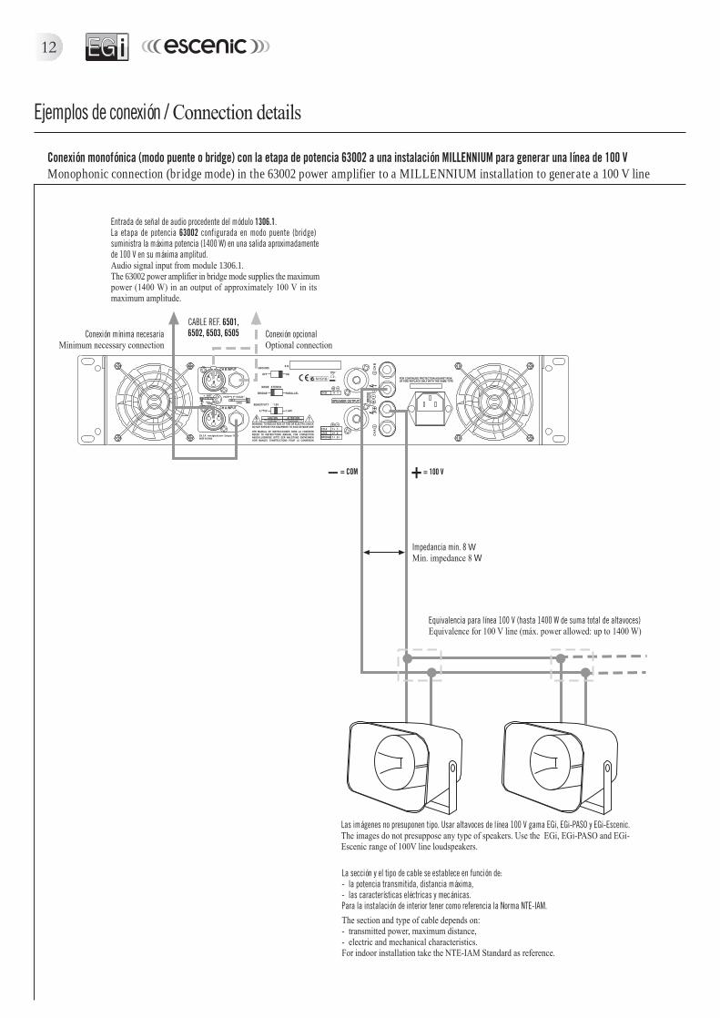
La sección y el tipo de cable se establece en función de:- la potencia transmitida, distancia máxima,- las características eléctricas y mecánicas.Para la instalación de interior tener como referencia la Norma NTE-IAM.The section and type of cable depends on:- transmitted power, maximum distance,- electric and mechanical characteristics.For indoor installation take the NTE-IAM Standard as reference.
Las imágenes no presuponen tipo. Usar altavoces de línea 100 V gama EGi, EGi-PASO y EGi-Escenic.The images do not presuppose any type of speakers. Use the EGi, EGi-PASO and EGi-Escenic range of 100V line loudspeakers.
Conexión monofónica (modo puente o bridge) con la etapa de potencia 63002 a una instalación MILLENNIUM para generar una línea de 100 VMonophonic connection (bridge mode) in the 63002 power amplifier to a MILLENNIUM installation to generate a 100 V line
Entrada de señal de audio procedente del módulo 1306.1.La etapa de potencia 63002 configurada en modo puente (bridge)suministra la máxima potencia (1400 W) en una salida aproximadamentede 100 V en su máxima amplitud.Audio signal input from module 1306.1.The 63002 power amplifier in bridge mode supplies the maximumpower (1400 W) in an output of approximately 100 V in itsmaximum amplitude.
= 100 V= COM
Impedancia min. 8 WMin. impedance 8 W
Equivalencia para línea 100 V (hasta 1400 W de suma total de altavoces)Equivalence for 100 V line (máx. power allowed: up to 1400 W)
CABLE REF. 6501,6502, 6503, 6505Conexión mínima necesaria
Minimum necessary connectionConexión opcionalOptional connection
HOT +COLD –
GND
SIGNAL
GND
13
Instalación
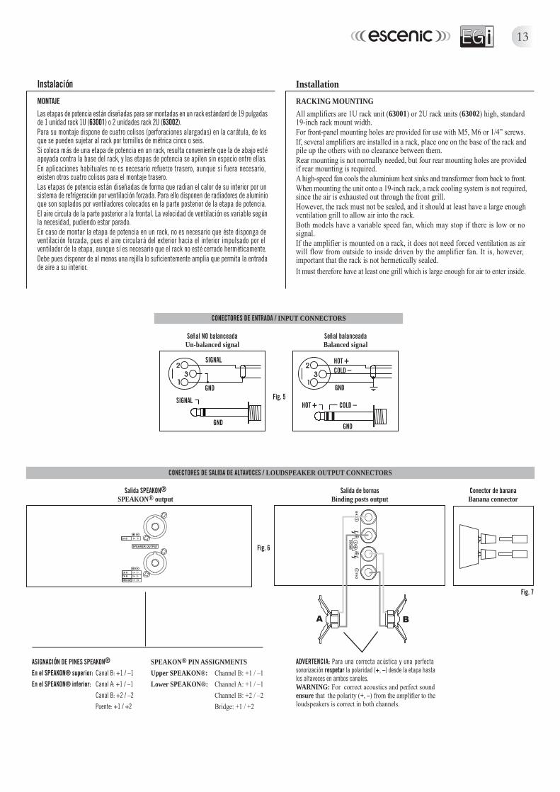
MONTAJELas etapas de potencia están diseñadas para ser montadas en un rack estándard de 19 pulgadasde 1 unidad rack 1U (63001) o 2 unidades rack 2U (63002).Para su montaje dispone de cuatro colisos (perforaciones alargadas) en la carátula, de losque se pueden sujetar al rack por tornillos de métrica cinco o seis.Si coloca más de una etapa de potencia en un rack, resulta conveniente que la de abajo estéapoyada contra la base del rack, y las etapas de potencia se apilen sin espacio entre ellas.En aplicaciones habituales no es necesario refuerzo trasero, aunque si fuera necesario,existen otros cuatro colisos para el montaje trasero.Las etapas de potencia están diseñadas de forma que radian el calor de su interior por unsistema de refrigeración por ventilación forzada. Para ello disponen de radiadores de aluminioque son soplados por ventiladores colocados en la parte posterior de la etapa de potencia.El aire circula de la parte posterior a la frontal. La velocidad de ventilación es variable segúnla necesidad, pudiendo estar parado.En caso de montar la etapa de potencia en un rack, no es necesario que éste disponga deventilación forzada, pues el aire circulará del exterior hacia el interior impulsado por elventilador de la etapa, aunque sí es necesario que el rack no esté cerrado herméticamente.Debe pues disponer de al menos una rejilla lo suficientemente amplia que permita la entradade aire a su interior.
Installation
RACKING MOUNTINGAll amplifiers are 1U rack unit (63001) or 2U rack units (63002) high, standard19-inch rack mount width.For front-panel mounting holes are provided for use with M5, M6 or 1/4” screws.If, several amplifiers are installed in a rack, place one on the base of the rack andpile up the others with no clearance between them.Rear mounting is not normally needed, but four rear mounting holes are providedif rear mounting is required.A high-speed fan cools the aluminium heat sinks and transformer from back to front.When mounting the unit onto a 19-inch rack, a rack cooling system is not required,since the air is exhausted out through the front grill.However, the rack must not be sealed, and it should at least have a large enoughventilation grill to allow air into the rack.Both models have a variable speed fan, which may stop if there is low or nosignal.If the amplifier is mounted on a rack, it does not need forced ventilation as airwill flow from outside to inside driven by the amplifier fan. It is, however,important that the rack is not hermetically sealed.It must therefore have at least one grill which is large enough for air to enter inside.
Fig. 5SIGNAL
GND GND
HOT + COLD –
Fig. 7
ADVERTENCIA: Para una correcta acústica y una perfectasonorización respetar la polaridad (+, –) desde la etapa hastalos altavoces en ambos canales.WARNING: For correct acoustics and perfect soundensure that the polarity (+, –) from the amplifier to theloudspeakers is correct in both channels.
Señal NO balanceadaUn-balanced signal
Conector de bananaBanana connector
Fig. 6
Salida SPEAKON®SPEAKON® output
Señal balanceadaBalanced signal
CONECTORES DE SALIDA DE ALTAVOCES / LOUDSPEAKER OUTPUT CONNECTORS
CONECTORES DE ENTRADA / INPUT CONNECTORS
ASIGNACIÓN DE PINES SPEAKON®
En el SPEAKON® superior: Canal B: +1 / –1En el SPEAKON® inferior: Canal A: +1 / –1
Canal B: +2 / –2Puente: +1 / +2
Salida de bornasBinding posts output
SPEAKON® PIN ASSIGNMENTSUpper SPEAKON®: Channel B: +1 / –1Lower SPEAKON®: Channel A: +1 / –1
Channel B: +2 / –2Bridge: +1 / +2
14
Instalación
CABLEADO DE SALIDA
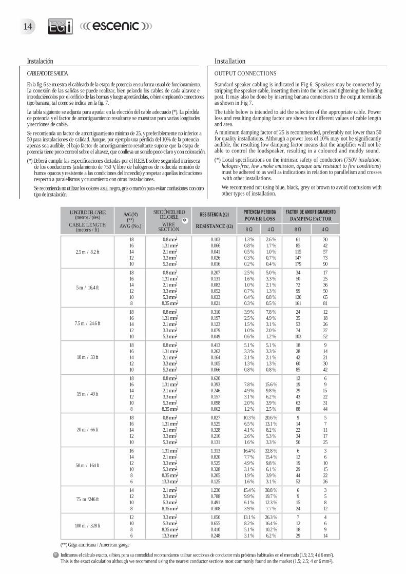
En la fig. 6 se muestra el cableado de la etapa de potencia en su forma usual de funcionamiento.La conexión de las salidas se puede realizar, bien pelando los cables de cada altavoz eintroduciéndolos por el orificio de las bornas y luego apretándolas, o bien empleando conectorestipo banana, tal como se indica en la fig. 7.La tabla siguiente se adjunta para ayudar en la elección del cable adecuado (*). La pérdidade potencia y el factor de amortiguamiento resultante se muestran para varias longitudesy secciones de cable.Se recomienda un factor de amortiguamiento mínimo de 25, y preferiblemente no inferior a50 para instalaciones de calidad. Aunque, por ejemplo una pérdida del 10% de la potenciaapenas sea audible, el bajo factor de amortiguamiento resultante supone que la etapa depotencia tiene poco control sobre el altavoz, que conlleva un sonido poco claro y con coloración.(*) Deberá cumplir las especificaciones dictadas por el R.E.B.T. sobre seguridad intrínseca
de los conductores (aislamiento de 750 V, libre de halógenos de reducida emisión dehumos opacos y resistente a las condiciones del incendio) y respetar aquellas indicacionesrespecto a paralelismos y cruzamiento con otras instalaciones.Se recomienda no utilizar los colores azul, negro, gris o marrón para evitar confusiones con otrotipo de instalación.
Installation
OUTPUT CONNECTIONS
Standard speaker cabling is indicated in Fig 6. Speakers may be connected bystripping the speaker cable, inserting them into the holes and tightening the bindingpost. It may also be done by inserting banana connectors to the output terminalsas shown in Fig 7.The table below is intended to aid the selection of the appropriate cable. Powerloss and resulting damping factor are shown for different values of cable lengthand area.A minimum damping factor of 25 is recommended, preferably not lower than 50for quality installations. Although a power loss of 10% may not be significantlyaudible, the resulting low damping factor means that the amplifier will not beable to control the loudspeaker, resulting in a coloured and muddy sound.(*) Local specifications on the intrinsic safety of conductors (750V insulation,
halogen-free, low smoke emission, opaque and resistant to fire conditions)must be adhered to as well as indications in relation to parallelism and crosses with other installations.We recommend not using blue, black, grey or brown to avoid confusions withother types of installation.
8 Ω 4 Ω 8 Ω 4 Ω
18 0.8 mm2 0.103 1.3 % 2.6 % 61 3016 1.31 mm2 0.066 0.8 % 1.7 % 85 4214 2.1 mm2 0.041 0.5 % 1.0 % 115 5712 3.3 mm2 0.026 0.3 % 0.7 % 147 7310 5.3 mm2 0.016 0.2 % 0.4 % 179 90
18 0.8 mm2 0.207 2.5 % 5.0 % 34 1716 1.31 mm2 0.131 1.6 % 3.3 % 50 2514 2.1 mm2 0.082 1.0 % 2.1 % 72 3612 3.3 mm2 0.052 0.7 % 1.3 % 99 5010 5.3 mm2 0.033 0.4 % 0.8 % 130 658 8.35 mm2 0.021 0.3 % 0.5 % 161 81
18 0.8 mm2 0.310 3.9 % 7.8 % 24 1216 1.31 mm2 0.197 2.5 % 4.9 % 35 1814 2.1 mm2 0.123 1.5 % 3.1 % 53 2612 3.3 mm2 0.079 1.0 % 2.0 % 74 3710 5.3 mm2 0.049 0.6 % 1.2 % 103 52
18 0.8 mm2 0.413 5.1 % 5.1 % 18 916 1.31 mm2 0.262 3.3 % 3.3 % 28 1414 2.1 mm2 0.164 2.1 % 2.1 % 42 2112 3.3 mm2 0.105 1.3 % 1.3 % 60 3010 5.3 mm2 0.066 0.8 % 0.8 % 85 42
18 0.8 mm2 0.620 12 616 1.31 mm2 0.393 7.8 % 15.6 % 19 914 2.1 mm2 0.246 4.9 % 9.8 % 29 1512 3.3 mm2 0.157 3.1 % 6.2 % 43 2210 5.3 mm2 0.098 2.0 % 3.9 % 63 318 8.35 mm2 0.062 1.2 % 2.5 % 88 44
18 0.8 mm2 0.827 10.3 % 20.6 % 9 516 1.31 mm2 0.525 6.5 % 13.1 % 14 714 2.1 mm2 0.328 4.1 % 8.2 % 22 1112 3.3 mm2 0.210 2.6 % 5.3 % 34 1710 5.3 mm2 0.131 1.6 % 3.3 % 50 25
16 1.31 mm2 1.313 16.4 % 32.8 % 6 314 2.1 mm2 0.820 7.7 % 15.4 % 12 612 3.3 mm2 0.525 4.9 % 9.8 % 19 1010 5.3 mm2 0.328 3.1 % 6.1 % 29 158 8.35 mm2 0.205 1.9 % 3.9 % 44 226 13.3 mm2 0.125 1.6 % 3.1 % 52 26
14 2.1 mm2 1.230 15.4 % 30.8 % 6 312 3.3 mm2 0.788 9.9 % 19.7 % 9 510 5.3 mm2 0.491 6.1 % 12.3 % 15 88 8.35 mm2 0.308 3.9 % 7.7 % 24 12
12 3.3 mm2 1.050 13.1 % 26.3 % 7 410 5.3 mm2 0.655 8.2 % 16.4 % 12 68 8.35 mm2 0.410 5.1 % 10.2 % 18 96 13.3 mm2 0.248 3.1 % 6.2 % 29 14
LONGITUD DEL CABLE(metros / pies)
CABLE LENGTH(meters / ft)
2.5 m / 8.2 ft
5 m / 16.4 ft
7.5 m / 24.6 ft
10 m / 33 ft
15 m / 49 ft
20 m / 66 ft
50 m / 164 ft
75 m /246 ft
100 m / 328 ft
AWG (Nº)
AWG (No.)
SECCIÓN DEL HILODEL CABLE
WIRESECTION
(**) Galga americana / American gauge
Indicamos el cálculo exacto, si bien, para su comodidad recomendamos utilizar secciones de conductor más próximas habituales en el mercado (1.5; 2.5; 4 ó 6 mm2).This is the exact calculation although we recommend using the nearest conductor sections most commonly found on the market (1.5; 2.5; 4 or 6 mm2).

15
MODELOMODEL
63001
63002
Instalación
CONEXIONADO A LA RED ELÉCTRICA
La toma de tensión de la red se realiza por la manguera de red, que lleva en su interior tresconductores: uno marrón, otro azul y el de toma de tierra bicolor amarillo-verde. Los dosprimeros corresponden a la fase y el neutro respectivamente de la toma de tensión. La tensiónnominal de funcionamiento es 230 V~ ±10%.A la tensión nominal se obtienen las potencias de salida que se listan en la sección deespecificaciones.Para la seguridad eléctrica, la etapa de potencia posee, en el interior, un fusible alojado ensu correspondiente portafusible. En caso de que se funda, debe ser sustituido por uno delmismo tipo solamente, y nunca uno de superior amperaje o más lento. El tipo de fusible vieneindicado alrededor del portafusible en la parte interior del amplificador.
Installation
CONNECTION TO MAINS
The mains lead has three isolated copper cables for connection to mains. Colourcodes are brown (live), blue (neutral) and yellowgreen (earth). Nominal ACvoltage is 230V~ ±10%.The power listed in the specifications section are obtained at the rated tension.For electrical safety, a fuse is housed inside the amplifier mounted on a fuseholder. If blown, replace it by one of exactly the same type. (Fuse type for eachmodel is indicated on the fuse itself as well as around the fuse holder).
FUSIBLE / FUSE 63001 63002
230 V~ 5 A 15 A
PROTECTION LED INDICATORWhen a channel's output is disconnected by the amplifier's protection, this yellowLED is on.A channel's protection may be triggered by:
• Overheating sensed at any part of a channel. When the amplifier has cooleddown, the channel's output will be connected and operation will resume. Thecontrol circuit has some degree of built-in hysterisis to avoid turn on and offoscillations.
• If one of the amplifier's channels shuts the music off and the red CLIP LEDis not on, the amplifier's overheating protections may have been activated toprotect the components from thermal damage.Overheating may be due to insufficient cooling, or you may be using a too lowload (for instance, 2 ohms, which is usually caused by plugging too manyspeakers to one channel).Once the amplifier cools down, the amplifier switches back on, but unless youcorrect the problem that made the amplifier shut down in the first place, chancesare the overheating protection will activate again in a few minutes. Ensure youhave appropriate cooling. If you are using too many speakers at the samechannel and need to continue working, try lowering the volume (5 dB lessmaybe all you need), and consider purchasing an additional amplifier.
• Presence of DC at a channel's output. Since it may severely damage speakers,the amplifier will deactivate the output in the event that DC levels are too high.Once DC is no longer present, the PROTECTION LED will turn off and outputis reactivated.
• Short-circuit at a channel's output (63001 only) or load impedance is too lowthis protection is activated. In this case, once the short circuit is gone the outputis NOT reactivated; the amplifier needs to be switched off and on to reactivate.
• When the amplifier is switched on, the output is also deactivated for a fewseconds to prevent dangerous transients from damaging the speakers.
CONSUMOS ELÉCTRICOS
Pueden verse para 230 V~ en la tabla que se acompaña. Multiplique por 2 para conseguirla corriente a 115V~.Las agencias internacionales de normativas de seguridad especifican el consumo de corrienteutilizando ruido rosa a 1/8 del nivel máximo de salida. Esto se hace para representar lacorriente requerida para reproducir un programa musical típico. La cifra de 1/3 de potenciarepresenta el consumo eléctrico en el peor caso, mientras que la cifra de máxima potenciarepresenta el consumo con señal senoidal a máxima potencia, circunstancia que nunca seproduce en la práctica.
POWER CONSUMPTION
Can be seen on the accompanying table for 230V~. Double the ratings to get the115V~ current consumption.International safety agencies specify AC consumption using pink noise at 1/8thof maximum power. This is done to represent the current requirements to play atypical musical programme.The 1/3rd power rating represents the worst case scenario, while the maximumpower represents consumption with sine wave signal, which will never occur inpractice.
16
ENTRADAS - XLR Y JACK DE 1/4" (6.3 mm)
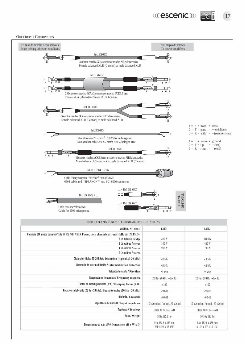
Ambos conectores están en paralelo y pueden usarse indistintamente. Aunque se puedenusar tanto señales balanceadas como no-balanceadas, se recomienda la utilización deconexiones balanceadas por su mayor capacidad de rechazo al ruido. El XLR es un conectorpreferible habitualmente al de jack de 6.3 mm ya que los conectores tienen anclaje mecánicoa la unidad, de forma que no se pueden soltar de forma accidental.Puesto que están en paralelo, es posible utilizarlos para llevar la señal a otras etapas depotencia. Por ejemplo, podemos entrar por el conector XLR del canal A y sacar la mismaseñal por el conector jack de 6.3 mm del mismo canal hacia otra etapa de potencia.Los gráficos de la pág. 17 muestran la conexión recomendada con diferentes tipos deconectores. Los conectores de la izquierda van a la fuente de sonido y los de la derecha vana la entrada de la etapa. Observe que en los conectores no balanceados de la izquierdaunimos dos terminales dentro del conector. En caso de aparecer zumbidos en el sistema,ponga el selector GROUND en posición OFF.
• Modo puenteEl modo puente o bridge se usa cuando no disponemos de una etapa de potencia losuficientemente grande para el altavoz utilizado, y viene a ser como la suma de amboscanales en una sola salida. La utilización en modo puente se detalla en el apéndice(ver pág. 18). No se recomienda la utilización del modo puente con cargas inferioresa 8 ohmios.
• Modo estéreoEste es el modo en que las etapas de potencia se suministran de fábrica. En este modo, laseñal conectada a la entrada A alimenta al canal A y, de igual forma, la entrada B alimentaal canal B.
• Modo paraleloEste modo es útil cuando queremos que los dos canales lleven la misma señal.La señal de entrada al canal A se pasa al canal B, de manera que con una sola entradaalimentamos los dos canales, sin necesidad de un cable exterior.Aunque la señal sea idéntica en ambos canales, los controles de volumen de cada canalpermanecen activos.
• ImpedanciaLa impedancia total de un grupo de altavoces conectados (en paralelo) a un canal deamplificador es la impedancia de cada altavoz dividida por el número de cajas. Porejemplo, dos cajas de 8 ohmios nos dan una impedancia total de 4 ohmios. No serecomienda bajar de 4 ohmios en modo estéreo o paralelo y de 8 ohmios en modo puente.
• Controles de nivelLos controles de nivel LEVEL nos permiten cambiar la ganancia de entrada de la señal.Aunque están relacionados con la potencia de salida, no son una representación directade ésta. Podemos tener máxima salida de potencia con estos potenciómetros a la mitad.De igual manera podemos infrautilizar el amplificador teniendo los volúmenes al máximosi la señal de entrada (por ejemploo del mezclador) no es lo suficientemente fuerte.Una posibilidad de uso de los controles de volumen es situarlos en una posición tal quecuando el mezclador está al máximo, no consigamos que las luces de CLIP se enciendano lo hagan sólo muy ocasionalmente.
INPUTS - XLR and 1/4" (6.3 mm) PHONE (commonly referred to as "JACK")
Both connectors are in parallel so any of them can be used to feed signal to anamplifier channel. Although unbalanced signals can be used, we recommend theuse of balanced connections for the greater immunity to interfering noise. XLRis normally preferred to 6.3 mm phone since it has a locking mechanism thatavoids accidental disconnection.Since they are in parallel, they can be used to feed the signal to another amplifier. Forexample, one could plug into channel A's XLR connector, and use the 6.3 mm ("jack")connector of the same channel to feed another amplifier with the same signal.The graphs in page 17 show the recommended connection from different connectortypes. The connectors on the left hand side plug into the sound sources such asmixers, and the connectors on the right plug into the amplifier's input connectors.Note that unbalanced to balanced connections have two terminals joined together(- and ground). If hum is present in the system try lifting ground by switchingto OFF the GROUND selector.
• Bridge modeBridge mode is used when we do not have a large enough amplifier for the speakerbeing used, and is similar to summing both channels into a single one. TheAppendix has information on how to enable this mode of operation (page 18).It is not recommended to use bridge mode with loads lower than 8 ohm.
• Stereo modeThis is the default mode when the unit is unpacked. The signal plugged intochannel A feeds channel A, and the signal plugged into channel B feedschannel B.
• Parallel modeThis mode is useful when the same signal is wanted for both channels.The signal plugged into channel A is passed along to channel B, so that bothchannels are fed with a single input, without the need of an external patch cable.Although the signal will be identical on both channels as derived from theinput to channel A, each channel's volume control remains active.
• ImpedanceTotal impedance for a group of loudspeakers connected (in parallel) to a singlechannel is the impedance of one of the speakers divided by how many we have.For example, two 8 ohm boxes give a 4 ohm impedance. You are discouraged touse impedance loads lower than 4 ohms in stereo mode and 8 ohm in bridge mode.
• LEVEL ControlsThe LEVEL rotary potentiometer is used for changing the input gain. Althoughrelated to output power, it is not a direct representation of if. Thus, we can havemaximum output power with the again at mid position. Similarly, we may havethe gain controls at maximum output if our source signal is not strong enough.One way to use the volume controls is to set them such that when the mixer'sfaders are at their mmaximum level, we are just below clipping level on theamplifier or clipping very occasionally.
17
Ref. EGi 6509 + ...
OPCI
ONAL
OPT
IONA
L
... + Ref. EGi 6507
... + Ref. EGi 6508
Ref. EGi 6505
Conector macho JACK 6.3 mm a conector macho XLR balanceadosMale balanced 6.3 mm Jack to male balanced XLR (Cannon)
Ref. EGi 6504
Cable altavoces 2 x 2.5mm2; 750 V libre de halógenosLoudspeaker cable 2 x 2.5 mm2; 750 V, halogen-free
Ref. EGi 6503
Conector hembra XLR a conector macho XLR balanceadosFemale balanced XLR (Cannon) to male balanced XLR
Ref. EGi 6502
2 Conectores macho RCA a 2 conectores macho JACK 6.3 mm2 male RCA (Phono) to 2 male JACK 6.3 mm
Ref. EGi 6501
Conector hembra XLR a conector macho XLR balanceadosFemale balanced XLR (Cannon) to male balanced XLR
Ref. EGi 6504 + 6506
Cable 6504 y conector "SPEAKON®" ref. EGi 65066504 cable and "SPEAKON®" ref. EGi 6506 connector
Conectores / Connectors
1 = S = malla = masa2 = T = punta = + (señal fase)3 = R = anillo = – (señal desfasada)
ESPECIFICACIONES TÉCNICAS / TECHNICAL SPECIFICATIONS
1 = S = sleeve = ground2 = T = tip = + (hot)3 = R = ring = – (cold)
De mesa de mezclas o equalizadoresFrom mixing tables or equalisers
A las etapas de potenciaTo power amplifiers
Cable para micrófono 6509Cable for 6509 microphone

18
SOLUCIÓN DE PROBLEMAS
Su etapa de potencia está fabricada con la más alta tecnología y constiyuye un exponentede calidad.Su tecnología modular hace que el acceso a cualquiera de sus módulos se realice de formasencilla, por lo que la eventual reparación tiene lugar de forma rápida.
OBSERVACIONES
ATENCIÓN: El modo puente no permite hacer medidas en la salida referenciadas a tierra, porlo que, para realizar medidas en las salidas del amplificador es necesaria una sondadiferencial.
• En caso de no funcionar la etapa de potencia dando apariencia de falta de suministroeléctrico, revise el mismo, así como el fusible de entrada, que en caso de estar fundidodebe sustituirse por otro del mismo amperaje y tipo. Si se fundiera de nuevo el fusible,mande la etapa de potencia a reparar al distribuidor.
• En caso de que no existiera señal de salida, verifique el conexionado, y si se enciendeel LED de clip, verifique un posible cortocircuito en la línea de altavoces.
• El piloto LED de señal (SIGNAL) le muestra si hay señal en las entradas de la etapa depotencia, aunque los controles de volumen estén a cero, lo que resulta útil para la resoluciónde problemas.
• En caso de existir una corriente continua en la entrada, su amplificador desconecta lalínea de altavoces con el fin de que no se deterioren; en este caso permanece encendidoel LED amarillo del área de seguridad (PROTECTION). Usted puede verificar si este fenómenoocurre, bien midiendo la tensión de offset de la fuente de sonido, o bien desconectándola,con lo que se apagaría el LED amarillo.
• El túnel de ventilación debe permanecer libre de obstrucciones y por lo tanto debe estarlimpio en todo momento. Con el uso puede acumular polvo. No olvide revisar la unidadperiódicamente.
TROUBLESHOOTING
EGi amplifiers have been designed and built with the best electronic componentsavailable for utmost reliability.Its modular mounting provides easy access to technical service.
OBSERVATIONS
WARNING: The bridge mode does not allow to take measurements at the outputreferenced to ground so, to take measurements at the amplifier's outputs, adifferential probe is required.
• If the amplifier seems to have no mains supply, check the fuse. If it is blown,replace it by another of exactly the same type. If it blows again, return theamplifier for inspection to an authorised dealer.
• If there are no signs of output signal, check connections. If clip LED is lit,check for a possible short-circuit in the speaker cables.
• The SIGNAL LED indicate signal presence regardless of the INPUT LEVELcontrol, which can be useful in case of troubleshooting.
• If DC current is detected at the inputs, the amplifier will disconnect the outputand the yellow PROTECTION LED will indicate that the outputs have beendeactivated (no sound will be heard through the speaker system). You canverify the existence of DC, by measuring the offset voltage of the input source,or by disconnecting it from the amplifier, in which case the yellow LED willturn off.
• After a long time usage, the grills on the front panel and on the fan mayaccumulate dirt and dust. Be sure to keep them clean at all times to assureproper fan cooling. Ensure to make regular inspections.
APÉNDICE. UTILIZACIÓN DE LA ETAPA DE POTENCIA EN MODO PUENTE
El procedimiento para usar las etapas de potencia en modo puente es el siguiente:1. Apague la etapa de potencia.2. Baje al mínimo los dos controles de volumen. (Ambos atenuadores girados totalmente en
sentido contrario a las agujas de un reloj).3. Deberá entrar por la entrada XLR o jack de 6.3 mm del canal A.4. Seleccione la opción "Bridge".5. Conecte el altavoz de la siguiente forma:
El positivo (+) en borne rojo de salida del canal A y el negativo (–) en borne rojo de salidadel canal B o en caso de tener speakon seguir instrucciones de la etiqueta.
6. Coloque los dos potenciómetros rotatorios de volumen en la posición máxima (ambos atenuadoresgirados totalmente en el sentido de las agujas de un reloj).
7. Deberá manejar el control de atenuación desde el máster exterior al amplificador (porejemplo desde el mezclador).
NOTA: No se recomienda la utilización del modo puente en cargas inferiores a 8 ohmios.
APPENDIX. USE OF THE AMPLIFIER IN BRIDGE MODE
To operate an amplifier in bridge mode, follow these steps:1. Switch off the amplifier.2. Turn volume control potentiometers on the front panel to minimum position
(fully anticlockwise).3. Connect input signal to channel A's XLR or 6.3 mm phone connector.4. Select Bridge mode.5. Connect speakers as follows:
Connect (+) to red speaker terminal on channel A's output terminals.Connect (–) to red speaker terminal on channel B's output terminals.
6. Turn volume control potentiometers on the front panel to maximum position(fully clockwise).
7. Control volume levels from the mixer or pre-amp only.NOTE: Lower than 8 ohms loads in bridge mode are not recommended.

!"#$"%&'()*+&",-(.( ".,'"+&",-(.(/0 !"# 12203 !"#454/0!"#
22676 !"#8348 !"# 3037 6$4$ !"#$"%&9").('"+&",-(.( 4327:;*,-(;<=)(<.*(;>('""*",?"@ !"#$"%A.9"))"&"'+&",-(.(
!"!#45430$4B4!4$C!"#C" $% !7//76D6 !"#/2$/2)$ !"# &/0E8 !"#
!343$"%";"9"*)+&",-(.("!/04716 !"#'/0$04$ !"#
'" #!"454F86$0EG6$4EGE$ !"#$"%&"-)-+&",-(.(F86:;*,-(;<=)(<.*(;>('"'*)(@$"%"(=>+&",-(.(
% () )83G26 !"#
*"+E/0!"#$"%"',"'."+*H('."'*,-!)!/ !"#).4B04G26 !"#" #! !"#'+4B06006$C!"#
!"#$%&'(( ))***$%& +
,
--),
-
. ./! 0 (#$%&'(( ))***$%&